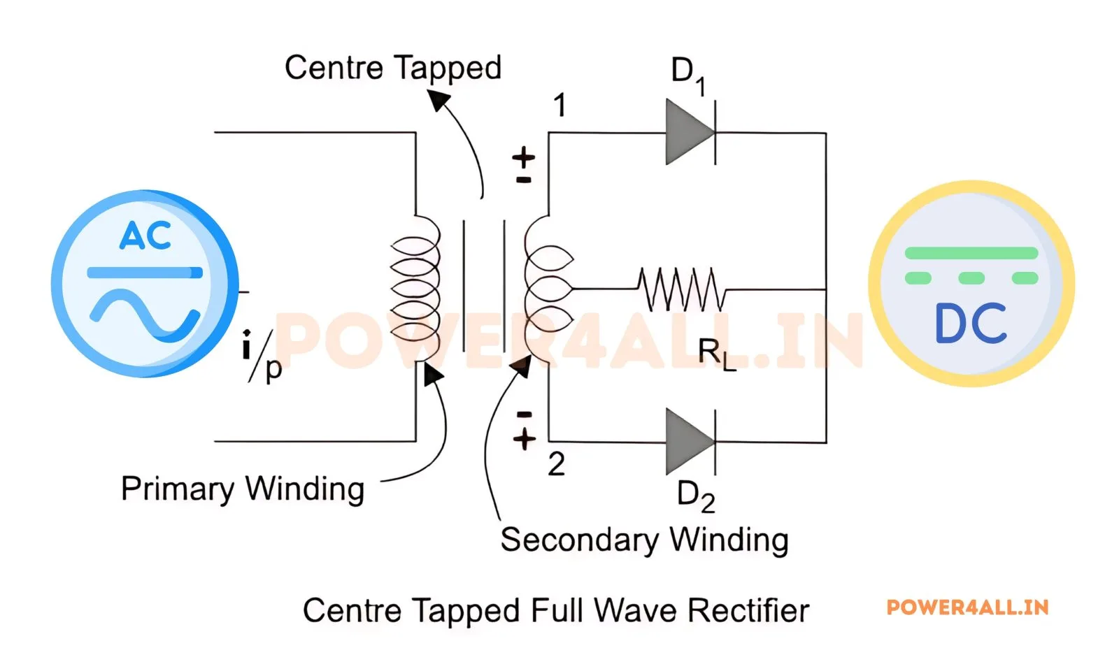
What is a centre-tapped full-wave rectifier?
A centre-tapped full-wave rectifier uses a transformer whose secondary winding has a centre tap, plus just two diodes. The centre tap is the load's common (return) point. During the positive half-cycle diode D1 conducts from the upper half of the secondary; during the negative half-cycle diode D2 conducts from the lower half. Both halves therefore drive the load in the same direction, giving full-wave rectification with only two diodes.
Output voltage & PIV equations
Here Vm is the peak voltage of each half of the centre-tapped secondary. The output is identical to a bridge rectifier, but the peak inverse voltage is twice as high: when one diode conducts, the other diode is exposed to the sum of both half-secondary voltages, so PIV = 2Vm. This simulator integrates the real circuit and checks Vdc, Vrms and PIV against these formulas.
Performance figures (resistive load)
| Average voltage Vdc | 2Vm/π = 0.637·Vm |
|---|---|
| RMS voltage Vrms | Vm/√2 = 0.707·Vm |
| Form factor | Vrms/Vdc = π/(2√2) ≈ 1.11 |
| Ripple factor | √(FF² − 1) ≈ 0.482 |
| Ripple frequency | 2f (100 Hz at 50 Hz) |
| Rectification efficiency | ≈ 81.2 % |
| Peak inverse voltage (PIV) | 2Vm |
Advanced options in this simulator
- Diode model: add a forward drop
V_fand on-resistanceR_on; only one diode conducts per half-cycle, so the drop isV_f + R_on·i(half that of a bridge). The accuracy check stays locked to the ideal2Vm/πenvelope. - Transformer: a turns ratio scales the peak half-secondary voltage
Vm— remember the diode PIV is2Vm. - Filter & protection: a series-L, shunt-C or LC output filter, an optional RC snubber, and a live protection-margin check of the diode PIV = 2Vm and average current against the ratings you enter.
- Harmonic spectrum analysis: a real FFT of the output voltage or load current with the ripple / THD figure — dominated by the 2nd harmonic (2f).
- Export & capture: download the full waveform data as CSV, a text report, or a PNG screenshot of the scope.
Centre-tapped vs bridge rectifier
| Feature | Centre-tapped | Bridge |
|---|---|---|
| Diodes | 2 (one drop) | 4 (two drops) |
| Transformer | Centre-tapped (bulky) | Ordinary / none |
| PIV per diode | 2Vm | Vm |
| Average voltage | 2Vm/π | 2Vm/π |
| Ripple factor | 0.48 | 0.48 |
Compare with the full-wave bridge rectifier simulator.
Advantages, disadvantages & applications
Advantages: only two diodes, so only one diode voltage drop in the conduction path (slightly higher efficiency at low output voltage), and a simple, isolated design. Disadvantages: needs a bulky, more expensive centre-tapped transformer, diodes must be rated for the higher PIV = 2Vm, and transformer utilisation is poorer. Applications: low-voltage DC supplies, valve/tube equipment, and audio power supplies where the centre-tapped transformer is already present.
Frequently asked questions
What is the average output voltage of a centre-tapped rectifier?
Vdc = 2Vm/π ≈ 0.637·Vm, where Vm is the peak of each half of the centre-tapped secondary — the same as a bridge rectifier.
Why is the PIV of a centre-tapped rectifier 2Vm?
When one diode conducts, the non-conducting diode is connected across the whole secondary winding, so it sees the sum of both half-secondary voltages — a peak of 2Vm, twice the bridge's PIV.
How many diodes does it use?
Only two, one per half-cycle — but it needs a centre-tapped transformer, unlike the four-diode bridge.
What is its ripple factor and efficiency?
Ripple factor ≈ 0.48 and efficiency ≈ 81.2 %, the same as a bridge rectifier because both are full-wave.
Centre-tapped or bridge — which should I use?
Bridge is usually preferred (lower diode PIV, no special transformer). Centre-tapped is used when a tapped transformer is already available or only two diodes are wanted.
What does the harmonic spectrum show?
An FFT of the output voltage (or load current). Like the bridge, the centre-tapped output is symmetric so odd harmonics cancel and the ripple is dominated by the 2nd harmonic (2f). Switch between the voltage and current spectra and choose how many harmonics to display.