Direct Matrix Converter
A grid of nine bidirectional switches connects any input phase to any output phase, turning a fixed three-phase supply into a variable-voltage, variable-frequency output — with no DC link and no bulky capacitors.
Introduction
A direct matrix converter (often just called a matrix converter) is a direct AC-to-AC converter: it changes a fixed three-phase supply straight into a three-phase output of adjustable voltage and adjustable frequency, without ever converting to DC in between. The name comes from its heart — a matrix (grid) of nine switches arranged in three rows and three columns, so that any of the three input phases can be joined to any of the three output phases.
What makes it special is what it does not have. A conventional variable-frequency drive first rectifies the mains to DC, stores energy in a large electrolytic capacitor (the "DC link"), and then inverts that DC back to AC. The matrix converter skips the middle step entirely: there is no DC link and no energy-storage capacitor. Because the input is connected directly to the output through the switches, the instantaneous input power always equals the instantaneous output power.
Removing the bulky capacitor makes the converter compact, long-lived and capable of power flow in both directions (motoring and regenerating). The trade-off is that all nine switches must be bidirectional — able to block and conduct in both directions — and the control that decides, moment by moment, which switches are closed is more involved. The rest of this page builds the circuit up from that idea.
Block Diagram
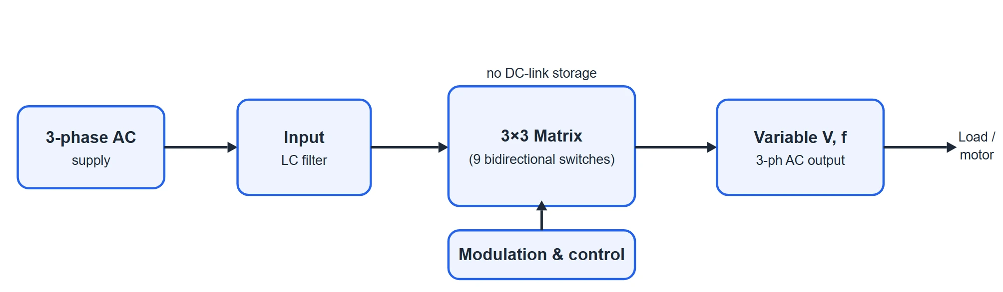
At the block level the converter is refreshingly simple. The three-phase supply passes through a small input filter (a set of inductors and capacitors that smooth the current the switches draw) and then straight into the 3×3 switch matrix. A modulation and control unit decides the switching pattern and produces the variable-voltage, variable-frequency output. Note what is missing between input and output: there is no rectifier, no DC link and no separate inverter stage.
Circuit Diagram & Bidirectional Switch
The power circuit is shown below. Three input phases — a, b and c — run in from the left as three horizontal rails. Three output phases — A, B and C — are formed by three vertical collectors that feed the load. At every point where an output collector crosses an input rail there is a bidirectional switch, giving a 3×3 array of nine switches in total. The inset on the right shows what one of those switches is made of.
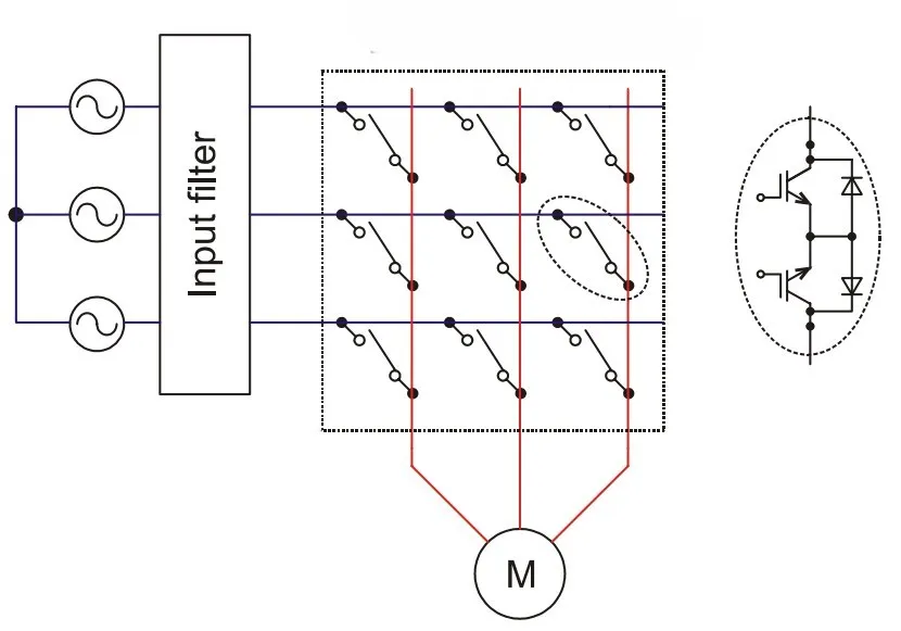
Reading the circuit:
- The three input phases a, b, c come from the balanced three-phase supply on the left (shown here in star with neutral N). Each phase becomes one horizontal rail that runs across the whole array.
- The nine switches are named by the pair of phases they join: SaA connects input a to output A, SbA connects input b to output A, and so on up to ScC. Each output phase therefore has three switches — one to each input phase.
- The three output phases A, B, C collect the selected pieces of input voltage and carry them to the three-phase load (very often an AC motor, shown as M).
- There is nothing else in the power path — no diodes bridge, no DC bus, no capacitor bank. The output is only ever a direct, switch-selected connection to the input.
Why the switches must be bidirectional
Because the output voltage and current are AC, each switch must be able to carry current in either direction and block voltage of either polarity. An ordinary transistor or a single diode cannot do this. The usual solution, shown in the inset, is to put two IGBTs back-to-back with a common emitter, each IGBT fitted with an anti-parallel diode. One IGBT-diode pair handles current in one direction, the other pair handles the reverse direction, and by gating them appropriately the switch can be turned on or off for either polarity. (A "common-collector" arrangement, or a single reverse-blocking IGBT, can do the same job.)
Working Principle
The trick of the matrix converter is time-averaging. The switches are turned on and off very fast — typically many kilohertz, far faster than either the supply or the desired output frequency. During each tiny switching period the output is connected in turn to different input phases for carefully chosen slices of time. Although the output jumps between input voltages instant by instant, its average over the switching period can be made equal to whatever value the desired output waveform needs at that moment.
Do this continuously and the string of averaged slices traces out a smooth sine wave — at any frequency you like, higher or lower than the mains. The output waveform is literally made from small pieces of the input waveforms, selected in sequence for defined lengths of time. The fraction of each switching period that a given switch is closed is called its duty cycle, and choosing the nine duty cycles correctly is exactly what the modulation strategy does.
The same switching also shapes the input current. By keeping the input current in phase with the input voltage, the converter can run at (near) unity input power factor — and it can just as easily be set to lead or lag, because input and output are decoupled by the modulation.
Modes of Operation (Switching States)
A matrix converter does not have "modes" in the sense a rectifier or chopper does. Instead, at every instant the nine switches sit in one of a fixed set of allowed switching states, and the converter works by stepping rapidly from one state to another. It is worth understanding these states, because the whole of the modulation is just a recipe for how long to dwell in each. (These are described in words only; the circuit itself is the one in Figure 2.)
The two rules every state must obey
Two hard safety rules limit which switch combinations are legal:
- Never short two input phases together. If two switches on the same output column were closed at once, they would connect two different input phases directly — a line-to-line short circuit through the switches. So for each output phase, at most one of its three switches may be closed.
- Never open an output line. The load is inductive, and an inductive current cannot be interrupted without a large voltage spike. So for each output phase, at least one switch must stay closed.
Put together, the rules say: for each of the three output phases, exactly one of its three switches is closed at any instant. Each output independently picks one of three inputs, so the number of legal states is 3 × 3 × 3 = 27 switching states. These 27 states fall into three natural groups.
Group 1 — Rotating (all three inputs used)
In these states the three outputs are connected to three different input phases — each input feeds exactly one output. There are 6 such states (the six ways to pair three outputs with three distinct inputs). They effectively pass the input set straight through in one order or another, and are mostly used by the older direct (Venturini-type) modulation.
Group 2 — Active (two outputs share an input)
Here two of the outputs are tied to the same input phase while the third output takes a different input. There are 18 of these states. They are the workhorses of space-vector modulation: each one applies a definite line-to-line voltage to the load and draws a definite input current, so combining them for the right durations synthesises both the desired output voltage vector and the desired input current.
Group 3 — Zero (all outputs on one input)
In these states all three outputs are connected to the same single input phase. There are 3 of them (all-on-a, all-on-b, all-on-c). With every output at the same potential, the load sees zero line-to-line voltage — these are the "freewheeling" states that let the modulator fill up the rest of each switching period without changing the average output.
Waveforms & Explanation
Start with the big picture. The top panel below shows the three input phase voltages (50 Hz mains). The bottom panel shows how one output phase voltage is built: in each short switching period the converter connects the output to whichever input pieces make the running average follow the desired sine (dashed). Here the target is deliberately drawn at a lower frequency (30 Hz) and reduced amplitude, so you can see the two headline abilities at once — the output frequency is not tied to the supply frequency, and the output is stitched from slices of va, vb and vc.
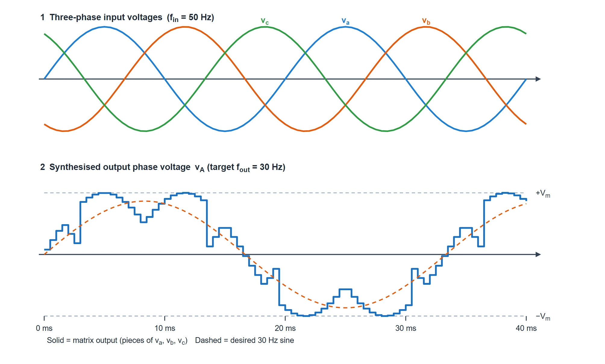
Reading the synthesis waveform
- Every slice is a piece of a real input voltage. The output never invents a new level — at each instant it equals va, vb or vc, because the output is only ever a switch-connection to one input.
- The average follows the dashed target. Fast switching means the eye (and the load) see the local average, which hugs the desired 30 Hz sine.
- The output frequency is independent of the input. The dashed target completes fewer cycles than the 50 Hz input over the same window — a matrix converter can synthesise higher or lower frequencies alike.
- The peak output is limited. The target amplitude is only about 0.866 of the input peak; a matrix converter cannot make its output larger than this without distortion (explained under the transfer ratio below).
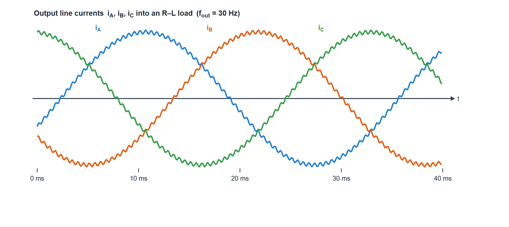
Because a real load is inductive, it filters those fast voltage steps into smooth currents. The three output line currents come out as clean, balanced sine waves at the chosen output frequency, 120° apart, carrying only a small high-frequency switching ripple:
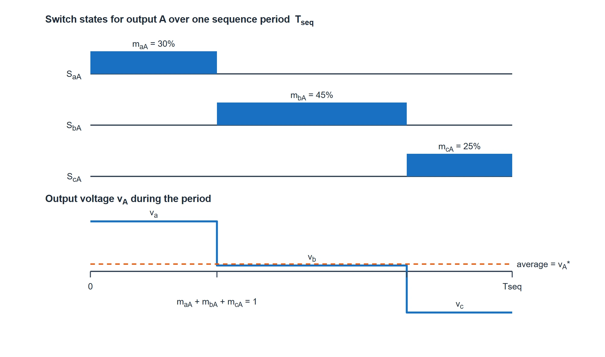
Finally, zoom in on a single switching period for output phase A. Exactly one of its three switches is closed at a time; the length of each "on" interval is that switch’s duty cycle (maA, mbA, mcA), and the three add up to one. The output voltage is therefore a short piece of va, then vb, then vc, and its time-average over the period equals the value the target sine needs right then:
Modulation & Voltage Transfer Ratio
The relationship between the input and output voltages is captured by a modulation matrix. If mij is the fraction of each switching period for which the switch joining input phase i to output phase j is closed (its duty cycle), then the three output phase voltages are the duty-weighted sums of the three input phase voltages:
∣ vB ∣ = ∣ maB mbB mcB ∣ ∣ vb ∣
⌊ vC ⌋ ⌊ maC mbC mcC ⌋ ⌊ vc ⌋
In each column the duty cycles obey maj + mbj + mcj = 1 (exactly one switch of that output is closed at any instant). The input currents follow the transpose of the same matrix, which is why the one set of switches controls both the output voltage and the input current at the same time.
The 0.866 voltage transfer ratio
Because each output is only ever connected to an input — never boosted — a matrix converter can only ever produce an output that is smaller than the input. For undistorted sinusoidal operation the largest possible ratio of output to input voltage magnitude is:
This 0.866 ceiling is a fundamental property of the topology, not a design shortcoming. It can be nudged higher only with over-modulation, which reintroduces low-order harmonics. In exchange for accepting that ceiling you get sinusoidal input and output currents, adjustable input power factor, and full four-quadrant (bidirectional) power flow — all from a single stage with no DC-link capacitor.
Advantages & Disadvantages
Advantages
- No DC-link capacitor. Removing the bulky, failure-prone electrolytic capacitor gives a compact, lightweight converter with a long service life.
- Bidirectional power flow. Energy can pass from supply to load or back again, so the drive naturally supports regenerative braking and four-quadrant operation.
- Sinusoidal input and output currents with a small input filter, and adjustable input power factor (unity if wanted).
- Output frequency is unrestricted by the supply frequency — higher or lower, both are possible.
Disadvantages
- Voltage transfer ratio limited to 0.866 — the output cannot reach the full input voltage.
- High device count — nine bidirectional switches (eighteen IGBTs and eighteen diodes).
- Complex commutation. Because there is no freewheeling diode path, switching between input phases needs a carefully timed multi-step commutation to avoid both shorting the inputs and opening the load.
- Sensitive to input disturbances and usually needs a protective clamp circuit, since there is no DC-link capacitor to ride through dips or absorb spikes.
Applications
- Compact AC motor drives where size, weight and long life matter more than reaching full output voltage.
- Aerospace and defence actuators and drives, which benefit from removing heavy, temperature-sensitive electrolytic capacitors.
- Wind-energy and other generation systems that need clean, bidirectional grid interfacing.
- Regenerative and four-quadrant drives for lifts, cranes and traction, where energy is fed back to the supply during braking.
- Variable-speed constant-frequency and other specialised AC-to-AC power-conditioning tasks.