Capacitor Mastery Guide
Master the fundamentals of capacitors, energy storage, and their critical role in modern electronics through interactive learning
Complete Learning Path - Capacitor Fundamentals to Applications
Navigate through comprehensive coverage of capacitors from basic principles to advanced applications
What is a Capacitor?
A capacitor is a fundamental passive electronic component specifically designed to store electrical energy in the form of an electric charge. Unlike resistors that dissipate energy as heat, and inductors that store energy in magnetic fields, capacitors accumulate energy in electric fields created between charged conductors.
C = Q / V
Capacitance (C) equals charge (Q) divided by voltage (V)
Key Understanding
The larger the capacitance value, the more charge the capacitor can store at a given voltage. This relationship is linear - doubling the capacitance doubles the stored charge for the same voltage.
Historical Context
The first capacitor was invented in 1745-1746 independently by Ewald Georg von Kleist and Pieter van Musschenbroek. Known as the "Leyden jar," it consisted of a glass jar with metal foil inside and outside. This simple device could store significant electrical charge and demonstrated the principle that would later become essential to all electronic circuits.
Why Capacitors are Essential
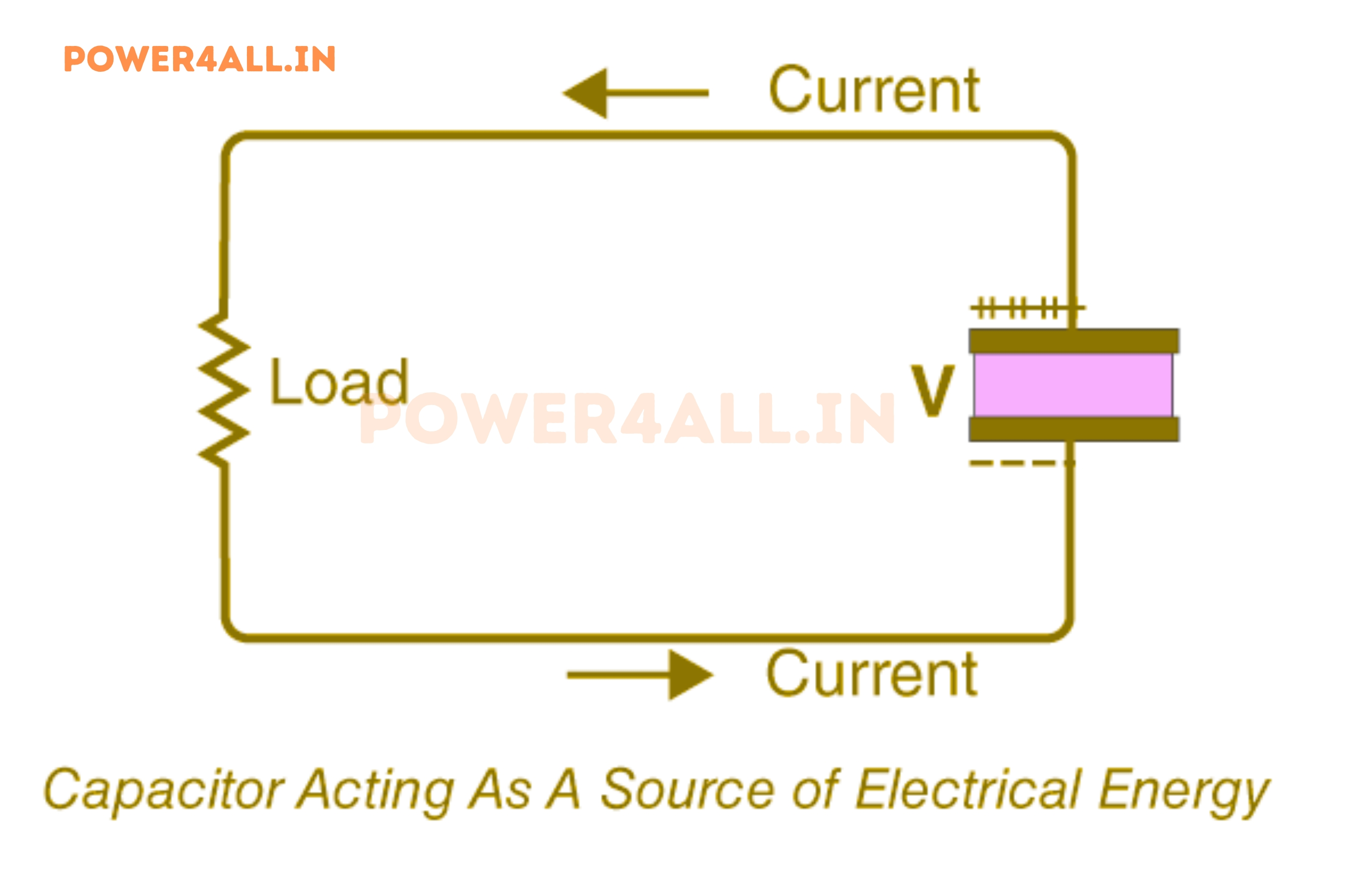
Instantaneous Energy Storage
Unlike batteries that rely on chemical reactions, capacitors store energy electrostatically, allowing for virtually instantaneous charge and discharge cycles. This makes them ideal for applications requiring rapid energy delivery.
High Power Density
Capacitors can deliver stored energy much faster than batteries, providing high power output for short durations. This characteristic is crucial in applications like camera flashes, defibrillators, and power supply filtering.
Unlimited Cycle Life
Ideal capacitors can be charged and discharged millions of times without degradation, unlike batteries which have limited charge-discharge cycles. This makes them excellent for applications requiring frequent cycling.
Wide Operating Temperature
Many capacitor types can operate over extreme temperatures (-55°C to +125°C or even higher), making them suitable for aerospace, automotive, and industrial applications where temperature stability is crucial.
Modern Applications Overview
Today's capacitors range from tiny ceramic chips smaller than a grain of rice (used in smartphones) to massive units weighing several tons (used in power grid applications). They're found in:
- Every electronic device: Power supply filtering, signal coupling, timing circuits
- Electric vehicles: Regenerative braking systems, power electronics
- Renewable energy: Solar inverters, wind turbine controllers
- Medical devices: Defibrillators, pacemakers, imaging equipment
- Industrial equipment: Motor starting, power factor correction
Construction Fundamentals
Understanding capacitor construction is fundamental to comprehending their behavior, limitations, and optimal applications. Every capacitor, regardless of type, consists of three essential components that work together to store electrical energy.
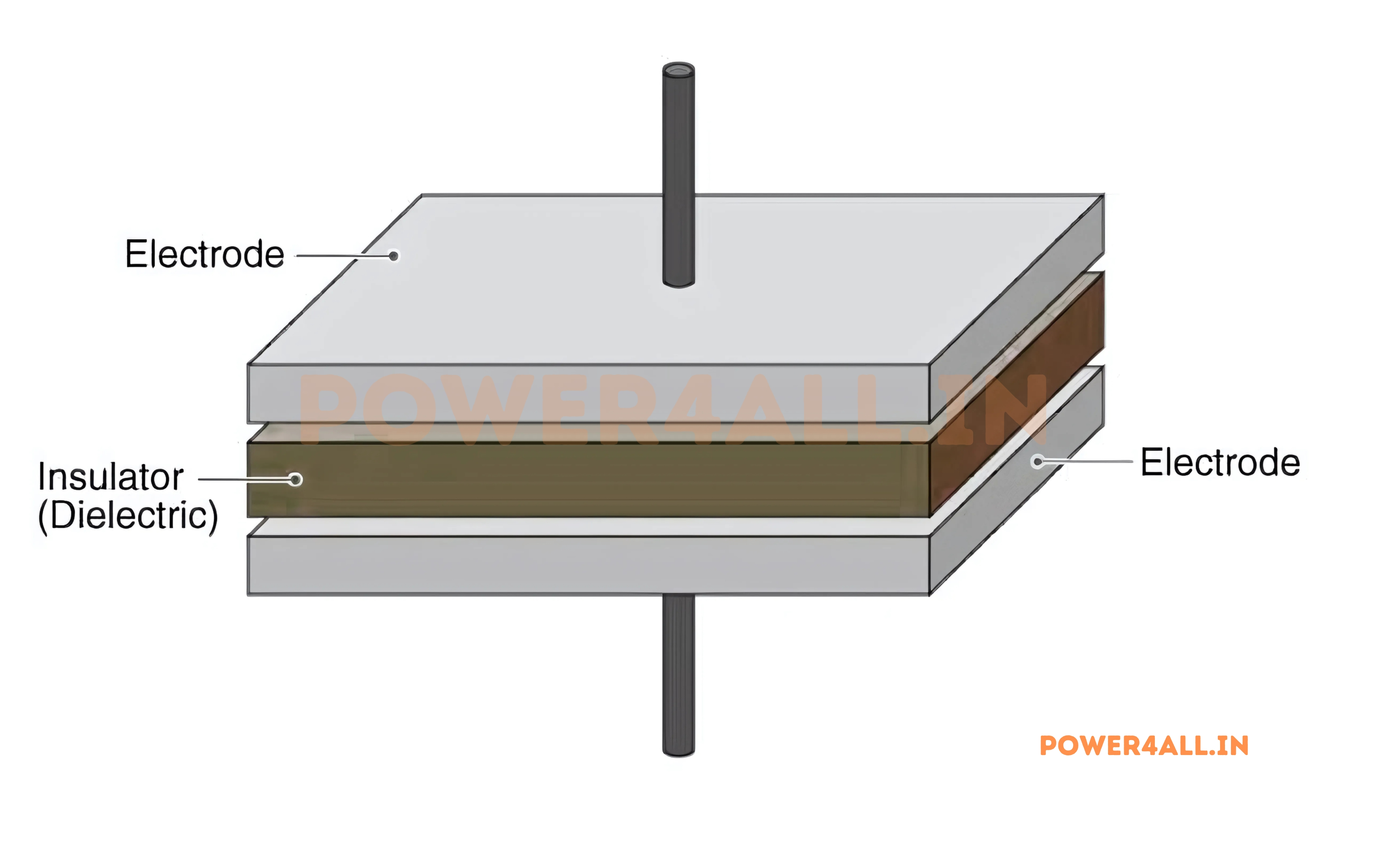
Essential Components
| Component | Common Materials | Primary Function | Key Properties Required | Impact on Performance |
|---|---|---|---|---|
| Conductive Plates | Aluminum, Tantalum, Silver, Copper, Nickel | Charge storage surfaces | High conductivity, corrosion resistance, stability | Determines ESR, current handling, reliability |
| Dielectric Material | Ceramic, Film, Electrolyte, Air, Glass, Mica | Electrical insulation & field enhancement | High dielectric constant, low loss, stability | Sets capacitance value, voltage rating, temperature stability |
| Terminal Connections | Tinned copper, Silver-plated leads, Gold plating | External circuit interface | Low resistance, reliable connection, oxidation resistance | Affects ESR, parasitic inductance, long-term reliability |
Detailed Construction Analysis
Conductive Plates: The Charge Carriers
The conductive plates are where electrical charges accumulate. Their design significantly impacts the capacitor's performance characteristics:
Material Selection Criteria
Aluminum
Advantages: Lightweight, cost-effective, forms stable oxide layer
Applications: Electrolytic capacitors, power applications
Conductivity: 37.7 MS/m (megasiemens per meter)
Tantalum
Advantages: Excellent stability, high capacitance density
Applications: High-reliability circuits, aerospace
Conductivity: 7.6 MS/m, superior oxide formation
Silver
Advantages: Highest conductivity, excellent RF performance
Applications: High-frequency circuits, precision applications
Conductivity: 63.0 MS/m, lowest loss at high frequencies
Surface Area Enhancement Techniques
Electrochemical Etching
Aluminum electrolytic capacitors use electrochemical etching to create microscopic tunnels and pits in the aluminum foil surface. This process can increase the effective surface area by 10-100 times compared to smooth foil.
- Tunnel formation: Creates cylindrical pores 20-200nm in diameter
- Surface roughening: Increases area through microscopic texture
- Multi-level etching: Creates branched structures for maximum area
Dielectric Materials: The Energy Storage Medium
The dielectric material is arguably the most critical component, as it determines the capacitor's fundamental characteristics. It must provide electrical insulation while enhancing the electric field strength.
How Dielectrics Work
When an electric field is applied across a dielectric material, its molecules undergo polarization:
Dielectric Properties Comparison
| Material | Dielectric Constant (εᵣ) | Breakdown Voltage (kV/mm) | Loss Factor (tan δ) | Temperature Stability |
|---|---|---|---|---|
| Vacuum/Air | 1.0 | 3.0 | 0 | Perfect |
| Polypropylene | 2.2 | 650 | 0.0002 | Excellent |
| Ceramic (NPO) | 8-12 | 35 | 0.001 | ±30ppm/°C |
| Ceramic (X7R) | 3000-4000 | 25 | 0.025 | ±15% |
| Aluminum Oxide | 8-10 | 15 | 0.01-0.1 | ±20% |
Advanced Construction Techniques
Multilayer Ceramic Construction
Modern MLCCs (Multilayer Ceramic Capacitors) stack hundreds of extremely thin ceramic layers (1-10 μm) with interleaved electrodes.
- Layer count: 100-1000+ layers in a single component
- Electrode thickness: 0.5-2 μm of precious metals
- Co-firing process: Simultaneous sintering at 1200-1350°C
- Termination: Multiple metallic layers for reliable connection
Wound Film Construction
Film capacitors use precisely controlled winding of metallized plastic films to achieve consistent performance.
- Film thickness: 3-50 μm depending on voltage rating
- Metallization: Vacuum-deposited aluminum 20-50 nm thick
- Winding tension: Controlled to prevent delamination
- Self-healing: Designed-in clearance of local faults
Electrolytic Formation
Electrolytic capacitors use electrochemical processes to form ultra-thin oxide dielectrics.
- Oxide thickness: 1.2-1.5 nm per volt of formation voltage
- Formation process: Controlled current anodization
- Electrolyte types: Liquid, solid polymer, or hybrid
- Reformation: Self-healing through re-anodization
Manufacturing Quality Control
Modern capacitor manufacturing involves sophisticated quality control measures:
Critical Process Parameters
- Material purity: 99.9%+ purity for dielectric materials
- Thickness control: ±0.1 μm tolerance on thin films
- Atmosphere control: Inert gas environments prevent contamination
- Temperature profiles: Precise thermal cycling for proper bonding
- Electrical testing: 100% testing of critical parameters
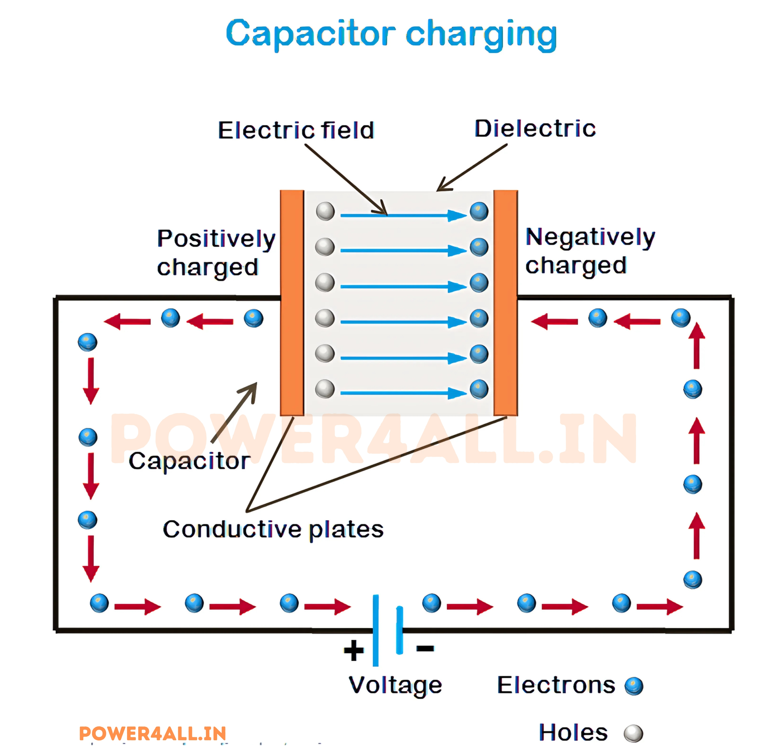
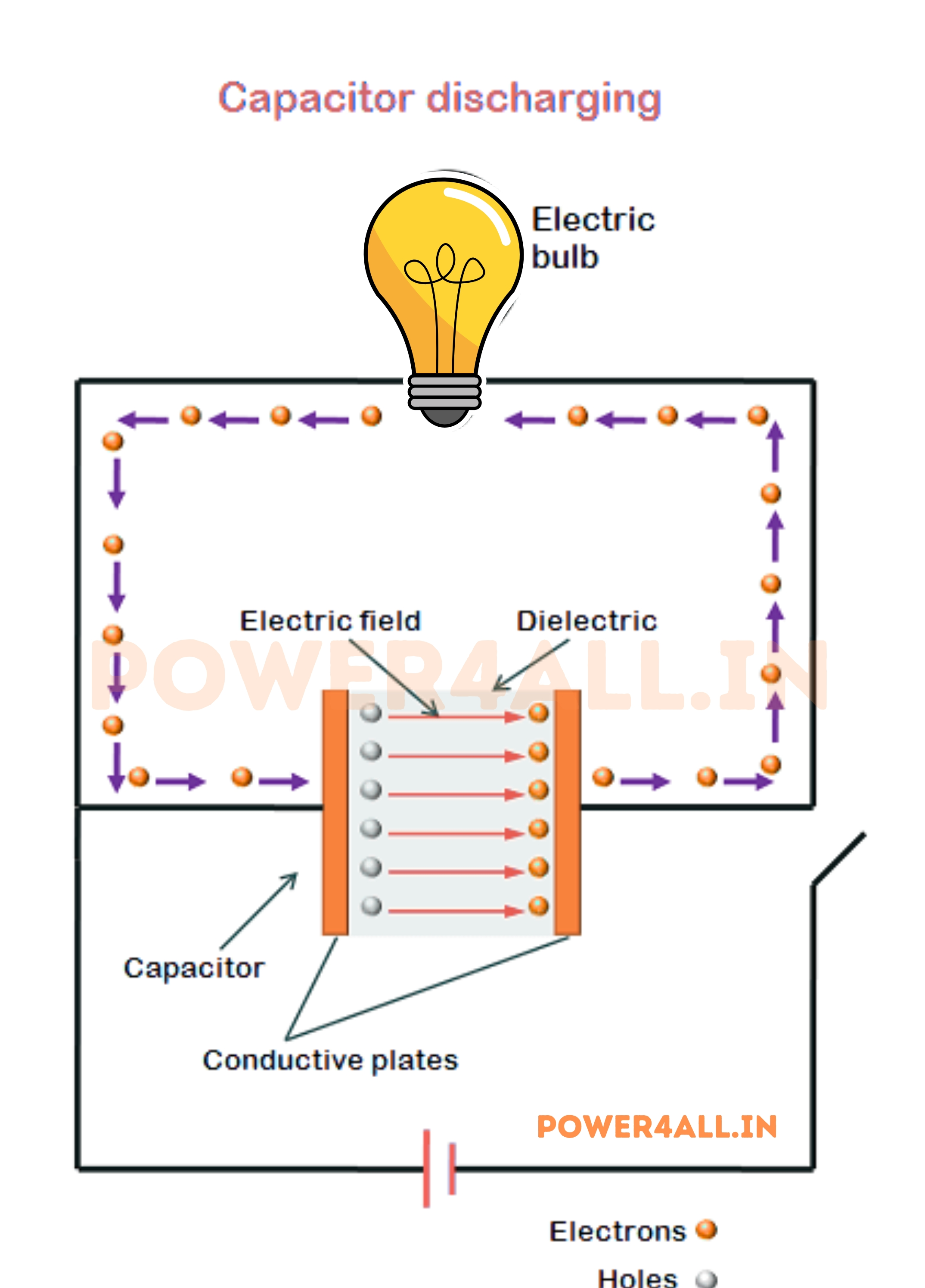
How Capacitors Work: The Complete Process
Understanding how capacitors work requires examining both the physical phenomena and the electrical behavior during charging, storage, and discharging phases. This knowledge is essential for proper circuit design and troubleshooting.
How Capacitors Charge
How Capacitors Discharge
The Charging Process: Step by Step
t = 0
Initial State
V = 0V
Q = 0C
I = Maximum
t = τ
63.2% Charged
V = 0.632 × Vₛ
Q = 0.632 × Qₘₐₓ
I = 0.368 × I₀
t = 3τ
95% Charged
V = 0.95 × Vₛ
Q = 0.95 × Qₘₐₓ
I = 0.05 × I₀
t = 5τ
99% Charged
V ≈ Vₛ
Q ≈ Qₘₐₓ
I ≈ 0
Where τ (tau) = RC = time constant
Mathematical Analysis of Capacitor Behavior
V(t) = Vₛ × (1 - e^(-t/RC))
Voltage across capacitor during charging
I(t) = (Vₛ/R) × e^(-t/RC)
Current during charging (exponential decay)
Detailed Physics of Operation
Electric Field Physics
The fundamental physics behind capacitor operation involves the creation and maintenance of electric fields between charged conductors.
Electric Field Strength
E = V / d
Electric field strength (V/m) = Voltage / Distance
The electric field between capacitor plates is nearly uniform (except at edges), creating a predictable energy storage mechanism. The field strength determines:
- Energy density: Higher field strength stores more energy per unit volume
- Breakdown risk: Excessive field strength causes dielectric failure
- Force between plates: Attractive force = ½ε₀εᵣE²A
Energy Storage Mechanism
Energy in a capacitor is stored in the electric field itself, not in the plates. The energy density in the electric field is:
u = ½ε₀εᵣE²
Energy density in electric field (J/m³)
Practical Example: Energy Calculation
Given: 1000μF capacitor charged to 12V
Energy stored: E = ½CV² = ½ × 1000×10⁻⁶ × 12² = 0.072 Joules
Equivalent: This energy could light a 1W LED for 0.072 seconds or lift a 1g mass by 7.3 meters!
Charge Movement and Current Flow
Understanding current flow during capacitor operation clarifies many circuit behaviors and design considerations.
Charging Phase Analysis
Discharging Behavior
During discharge through a resistor, the process reverses:
V(t) = V₀ × e^(-t/RC)
Voltage during discharge (exponential decay)
Safety Warning
Large capacitors can store dangerous amounts of energy. A 1000μF capacitor at 400V stores 80 Joules - enough to cause serious injury or death. Always discharge capacitors safely before handling.
AC Behavior and Impedance
Capacitors behave very differently with AC signals compared to DC, leading to their widespread use in filtering and coupling applications.
Capacitive Reactance
Xc = 1 / (2πfC)
Capacitive reactance (Ω) - inversely proportional to frequency
This fundamental relationship explains many capacitor applications:
- High frequencies: Low reactance → capacitor acts like short circuit
- Low frequencies: High reactance → capacitor acts like open circuit
- DC (f = 0): Infinite reactance → perfect open circuit
Phase Relationships
In AC circuits, capacitor current leads voltage by 90°:
I = C × (dV/dt)
Current equals capacitance times rate of voltage change
Practical Example: Power Supply Filtering
A 1000μF filter capacitor in a 60Hz power supply:
- At 60Hz: Xc = 1/(2π×60×1000×10⁻⁶) = 2.65Ω
- At 120Hz (ripple): Xc = 1.33Ω
- At 1kHz (switching noise): Xc = 0.16Ω
Lower reactance at higher frequencies provides better filtering of high-frequency noise.
Practical Implications
Time Constant Significance
τ = RC determines charging/discharging speed. Larger R or C values create longer time constants, affecting circuit timing and response.
Initial Current Spike
Uncharged capacitors draw maximum initial current. This can cause circuit breakers to trip or damage sensitive components if not controlled.
Frequency Selectivity
Capacitors naturally filter signals based on frequency, making them essential for power supply filtering, audio crossovers, and signal processing.
Energy Release Rate
Capacitors can release stored energy much faster than batteries, enabling applications like camera flashes and defibrillators.
Capacitance Fundamentals: Deep Understanding
Capacitance is the fundamental property that quantifies a capacitor's ability to store electrical charge. Understanding capacitance from both theoretical and practical perspectives is essential for proper component selection and circuit design.
Theoretical Foundation
Capacitance represents the ratio of electric charge stored on a conductor to the electric potential (voltage) applied to it. This relationship is linear for ideal capacitors, meaning doubling the voltage doubles the stored charge.
C = Q / V = ε₀ × εᵣ × A / d
Fundamental capacitance equation combining electrical and physical parameters
Unit System and Conversions
| Unit Name | Symbol | Value in Farads | Common Applications | Typical Range | Example Components |
|---|---|---|---|---|---|
| Farad | F | 1 | Supercapacitors, energy storage | 0.1F - 10,000F | Electric vehicle energy storage, UPS backup |
| Millifarad | mF | 10⁻³ | Large motor starting, power applications | 1mF - 100mF | AC motor run capacitors, power factor correction |
| Microfarad | μF | 10⁻⁶ | Power supply filtering, coupling | 0.1μF - 10,000μF | Electrolytic capacitors, DC power supplies |
| Nanofarad | nF | 10⁻⁹ | Audio circuits, timing circuits | 1nF - 1000nF | Film capacitors, ceramic capacitors |
| Picofarad | pF | 10⁻¹² | High-frequency, RF applications | 0.5pF - 10,000pF | Ceramic disc capacitors, trimmer capacitors |
Historical Note
The farad is named after Michael Faraday, the English scientist who discovered electromagnetic induction. One farad is an enormous capacitance - a 1F capacitor with 1mm plate separation would need plates approximately 10 kilometers on each side!
Factors Affecting Capacitance: Comprehensive Analysis
Capacitance is not a fixed property but varies with multiple factors including physical design, environmental conditions, applied voltage, and frequency. Understanding these dependencies is crucial for reliable circuit design.
Primary Design Factors
Plate Area (A) - Linear Relationship
Fundamental Relationship: C ∝ A (directly proportional)
Practical Implications:
- Doubling area doubles capacitance (if other factors remain constant)
- Multilayer advantage: N layers create (N-1) effective capacitors in parallel
- Edge effects: Non-uniform fields at plate edges slightly increase effective area
- Surface roughness: Microscopic texture can increase area 10-100×
Calculation Example
Standard parallel plate: 1cm × 1cm = 1cm² area
100-layer MLCC: 99 effective capacitors × 1cm² = 99cm² effective area
Etched aluminum: 50× surface multiplication = 4950cm² effective area
Total multiplication: Nearly 5000× the geometric area!
Distance Between Plates (d) - Inverse Relationship
Fundamental Relationship: C ∝ 1/d (inversely proportional)
Design Considerations:
- Halving distance doubles capacitance but halves voltage rating
- Manufacturing tolerance: ±10% thickness variation = ±10% capacitance variation
- Breakdown voltage: Thinner dielectrics have lower voltage ratings
- Temperature expansion: Thermal cycling can change effective thickness
| Application | Typical Thickness | Voltage Rating | Capacitance Density |
|---|---|---|---|
| High voltage | 50-200 μm | 1-10 kV | Low |
| General purpose | 5-50 μm | 50-1000V | Medium |
| High capacitance | 0.5-5 μm | 6-100V | High |
| Ultra-high density | 0.05-0.5 μm | 2-25V | Very High |
Dielectric Material (εᵣ) - Multiplication Factor
Fundamental Relationship: C ∝ εᵣ (directly proportional)
Material Selection Impact:
- Direct multiplier: εᵣ = 1000 gives 1000× capacitance vs. air
- Temperature stability: High-κ materials often less stable
- Voltage dependence: Some ceramics show capacitance reduction under DC bias
- Frequency response: Permittivity can vary with frequency
Dielectric Constant Comparison
Low-κ Materials (Stable)
- Air: εᵣ = 1.0
- PTFE: εᵣ = 2.1
- Polypropylene: εᵣ = 2.2
- NPO ceramic: εᵣ = 8-12
High-κ Materials (High Density)
- X7R ceramic: εᵣ = 3000
- Y5V ceramic: εᵣ = 10000
- Barium titanate: εᵣ = 5000-20000
- Lead zirconate titanate: εᵣ = 300-3000
Environmental Factors
Temperature Effects on Capacitance
Temperature affects capacitance through multiple mechanisms, with different materials showing vastly different behaviors.
Temperature Coefficient Classifications
| Material Type | Temperature Coefficient | Temperature Range | Typical Variation | Best Applications |
|---|---|---|---|---|
| NPO/C0G Ceramic | ±30 ppm/°C | -55°C to +125°C | ±0.54% | Precision timing, oscillators |
| X7R Ceramic | ±15% | -55°C to +125°C | ±15% | General purpose, decoupling |
| Y5V Ceramic | +22% to -82% | -30°C to +85°C | +22% to -82% | Non-critical applications |
| Polypropylene Film | -200 ppm/°C | -40°C to +105°C | -2.9% | Audio, precision circuits |
| Aluminum Electrolytic | ±20% | -40°C to +105°C | ±20% | Power supply filtering |
Physical Mechanisms
Real-World Example: Temperature Compensation
In a precision 10MHz crystal oscillator:
- Crystal temperature coefficient: -20 ppm/°C
- Compensation needed: +20 ppm/°C capacitance change
- NPO ceramic: +30 ppm/°C maximum - close enough for many applications
- Frequency stability achieved: ±5 ppm over temperature range
Voltage Dependence of Capacitance
Many capacitor types show significant capacitance variation with applied voltage, particularly important for DC-biased applications.
DC Bias Effects
Class 2 ceramic capacitors show the most dramatic voltage dependence:
X7R Capacitor Voltage Dependence Example
10μF, 25V X7R Capacitor
- 0V bias: 10.0μF (nominal)
- 5V bias: 8.5μF (-15%)
- 12V bias: 7.0μF (-30%)
- 20V bias: 5.5μF (-45%)
- 25V bias: 4.8μF (-52%)
Design Implications
- Always check capacitance at operating voltage
- May need larger nominal value to compensate
- Consider NPO if stability is critical
- Parallel combinations can help maintain capacity
AC Voltage Effects
AC Considerations
Large AC voltages can cause additional capacitance variation through:
- Peak voltage effects: Instantaneous high voltages reduce capacitance
- Self-heating: I²R losses in ESR cause temperature rise
- Electrostrictive effects: Mechanical deformation under electric field
Frequency Effects on Capacitance
Capacitance variation with frequency results from physical limitations and parasitic effects that become significant at higher frequencies.
Frequency-Dependent Mechanisms
Dielectric Relaxation
Molecular polarization cannot follow rapid field changes
- Low frequency: All polarization mechanisms active
- High frequency: Only electronic polarization responds
- Transition region: Gradual decrease in permittivity
- Loss peak: Maximum loss at relaxation frequency
Parasitic Inductance
Lead and internal inductance affects high-frequency behavior
- ESL effect: Equivalent series inductance
- Self-resonance: |XL| = |XC| frequency
- Above resonance: Capacitor acts inductive
- Lead length: ~1nH per mm of lead wire
Skin Effect
Current concentration at conductor surfaces
- ESR increase: Effective resistance rises with frequency
- Skin depth: Current penetration decreases
- Plate design: Affects current distribution
- Material choice: Lower resistivity helps
Self-Resonant Frequency
f₀ = 1 / (2π√(L×C))
Self-resonant frequency where capacitive and inductive reactances cancel
| Capacitor Type | Typical Capacitance | ESL Range | Self-Resonant Frequency | Useful Frequency Range |
|---|---|---|---|---|
| Leaded Ceramic | 100pF | 10-20nH | 100-150MHz | DC to 15MHz |
| SMD Ceramic 0603 | 100pF | 0.5-1nH | 500-700MHz | DC to 70MHz |
| SMD Ceramic 0201 | 10pF | 0.1-0.2nH | 3-5GHz | DC to 500MHz |
| Film Capacitor | 1μF | 10-50nH | 2-7MHz | DC to 700kHz |
| Electrolytic | 1000μF | 5-30nH | 100-300kHz | DC to 30kHz |
Types of Capacitors: Comprehensive Classification
Capacitors are available in numerous types, each optimized for specific applications based on dielectric materials, construction methods, and performance requirements. Understanding these types is essential for proper component selection in circuit design.
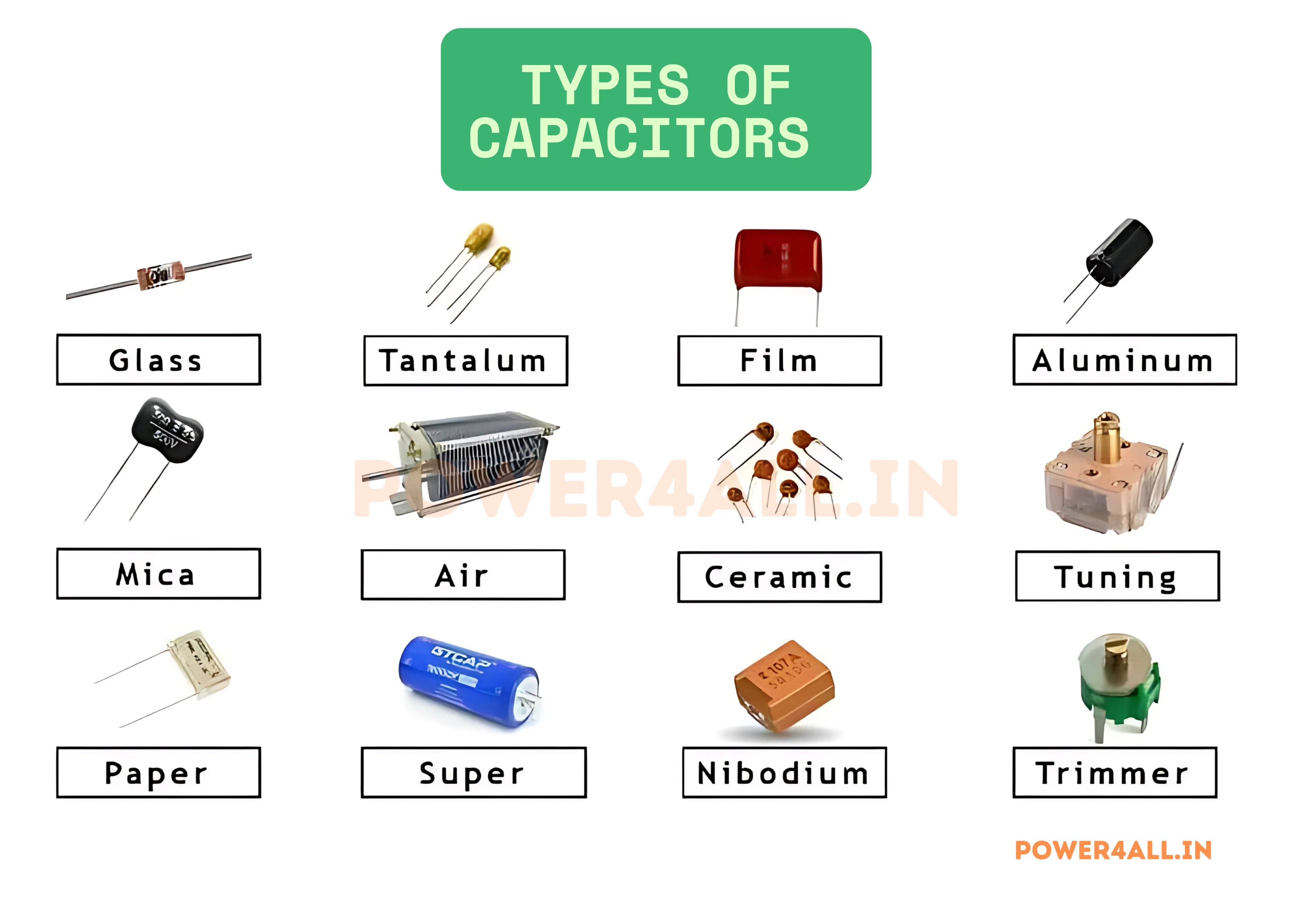
Classification by Dielectric Material
Ceramic Capacitors
Construction: Ceramic dielectric material between metal electrodes, available in disc, multilayer, and surface-mount configurations.
Class 1 Ceramics (NPO/C0G)
- Temperature coefficient: ±30 ppm/°C
- Capacitance range: 1pF to 47nF
- Voltage range: 25V to 3kV
- Applications: Timing circuits, filters, oscillators
Class 2 Ceramics (X7R, X5R, Y5V)
- Temperature coefficient: ±15% to ±22%/-82%
- Capacitance range: 100pF to 100μF
- Voltage range: 4V to 2kV
- Applications: Decoupling, power supply filtering
Code Interpretation
X7R: -55°C to +125°C, ±15% | Y5V: -30°C to +85°C, +22%/-82%
Electrolytic Capacitors
Construction: Metal oxide dielectric formed electrochemically on aluminum or tantalum, with liquid or solid electrolyte as second electrode.
Aluminum Electrolytic
- Capacitance range: 0.1μF to 1F
- Voltage range: 4V to 500V
- Temperature range: -40°C to +105°C (standard)
- Polarity: Must observe correct polarity
- Life expectancy: 1000-10000 hours at rated temperature
Tantalum Electrolytic
- Capacitance range: 0.1μF to 1500μF
- Voltage range: 2V to 50V
- Advantages: Stable, low ESR, long life
- Limitations: Expensive, sensitive to voltage spikes
ESR Comparison at 100kHz
- Standard aluminum: 100-1000 mΩ
- Low-ESR aluminum: 10-100 mΩ
- Solid tantalum: 10-200 mΩ
- Polymer aluminum: 5-50 mΩ
Film Capacitors
Construction: Plastic film dielectric with metallized electrodes or separate metal foils, wound or stacked configuration.
Common Film Materials
| Material | εᵣ | Max Temp | Characteristics |
|---|---|---|---|
| Polypropylene (PP) | 2.2 | 105°C | Low loss, self-healing |
| Polyester (PET) | 3.3 | 125°C | General purpose, economical |
| Polystyrene (PS) | 2.5 | 85°C | Precision, low loss |
| PTFE | 2.1 | 200°C | High temp, RF applications |
Applications by Type
- Polypropylene: Audio equipment, power electronics, motor drives
- Polyester: General purpose, timing circuits, coupling
- Polystyrene: Precision oscillators, measurement equipment
- PTFE: High-frequency, aerospace, military applications
Supercapacitors (Ultracapacitors)
Construction: Electrochemical double-layer or pseudocapacitive mechanisms using high surface area carbon electrodes.
Types and Characteristics
- EDLC (Electric Double Layer): Pure electrostatic storage
- Pseudocapacitors: Fast redox reactions at surface
- Hybrid capacitors: Combination of both mechanisms
Performance Specifications
- Capacitance range: 0.1F to 12,000F
- Voltage range: 2.3V to 5.5V per cell
- Energy density: 1-30 Wh/kg
- Power density: 500-10,000 W/kg
- Cycle life: 500,000 to 1,000,000+ cycles
Energy Storage Comparison
- Traditional capacitor: 0.01-0.3 Wh/kg
- Supercapacitor: 1-30 Wh/kg
- Lithium battery: 100-250 Wh/kg
- Lead-acid battery: 30-50 Wh/kg
Specialized Capacitor Types
Mica Capacitors
- Dielectric: Natural mica mineral
- Characteristics: Extremely stable, low loss, high Q
- Applications: RF circuits, precision oscillators
- Limitations: Expensive, limited values
Glass Capacitors
- Dielectric: Borosilicate glass
- Characteristics: Ultra-stable, radiation resistant
- Applications: Military, aerospace, nuclear
- Temperature range: -55°C to +200°C
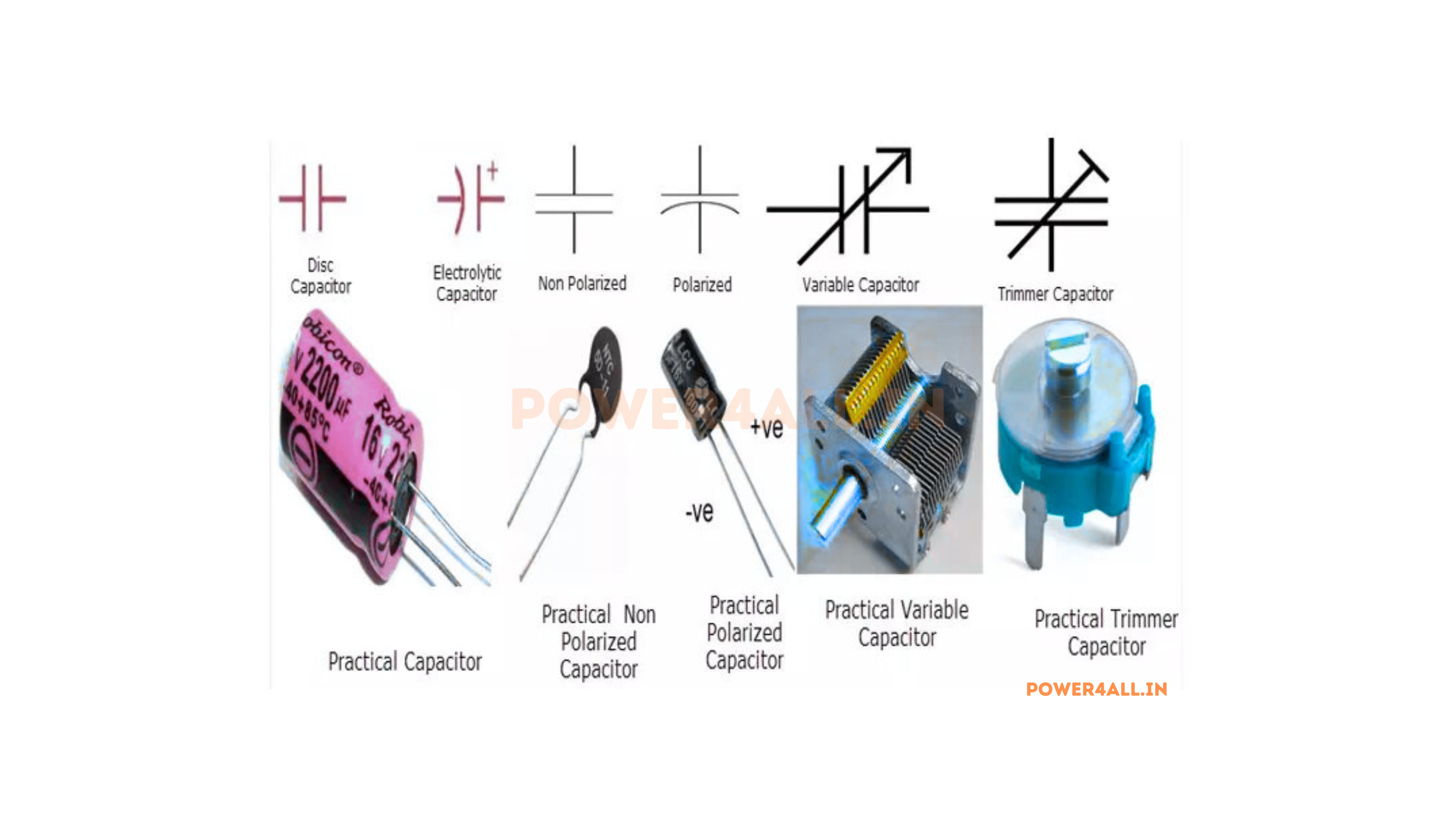
Air Variable Capacitors
- Construction: Interleaved plates with air dielectric
- Adjustment: Mechanical rotation changes overlap area
- Applications: Radio tuning, antenna matching
- Range: 10pF to 500pF typically
Variable and Trimmer Capacitors
Trimmer Capacitors
- Purpose: Fine adjustment during manufacturing or setup
- Construction: Ceramic, air, or film dielectric
- Adjustment: Screw mechanism changes plate spacing
- Range: 1pF to 100pF adjustment range
Varicap Diodes (Electronic Variable)
- Principle: Reverse-biased diode junction capacitance
- Control: Voltage-controlled capacitance
- Applications: Voltage-controlled oscillators, PLL
- Range: 2:1 to 10:1 capacitance variation
Classification by Construction Method
Surface Mount vs Through-Hole Technologies
| Aspect | Surface Mount (SMD/SMT) | Through-Hole (THT) |
|---|---|---|
| Size | Very compact (0201 to 2512) | Larger footprint, height clearance |
| Parasitic inductance | Very low (0.1-2nH) | Higher due to leads (2-20nH) |
| Assembly | Automated pick-and-place | Manual insertion or automated |
| Frequency performance | Excellent to GHz range | Limited by lead inductance |
| Mechanical strength | Solder joint dependent | Mechanically robust |
| Heat dissipation | Limited by thermal path | Better through leads and body |
| Replacement | Requires specialized equipment | Easy field replacement |
SMD Package Sizes
| Package Code | Dimensions (mm) | Typical Capacitance Range | Typical Applications |
|---|---|---|---|
| 0201 | 0.6 × 0.3 | 0.5pF - 10nF | Mobile devices, wearables |
| 0402 | 1.0 × 0.5 | 1pF - 1μF | Smartphones, tablets |
| 0603 | 1.6 × 0.8 | 1pF - 10μF | General purpose electronics |
| 0805 | 2.0 × 1.25 | 1pF - 47μF | Power supplies, automotive |
| 1206 | 3.2 × 1.6 | 1pF - 220μF | Power applications |
| 1210 | 3.2 × 2.5 | 100pF - 470μF | High-capacitance applications |
Dielectric Materials: The Heart of Capacitor Performance
The dielectric material is arguably the most critical component in a capacitor, as it determines not only the capacitance value but also the voltage rating, temperature stability, frequency response, and overall reliability. Understanding dielectric properties enables optimal capacitor selection for specific applications.
Fundamental Dielectric Properties
How Dielectrics Enhance Capacitance
Polarization Mechanisms
εᵣ = 1 + χₑ
Relative permittivity = 1 + electric susceptibility
The electric susceptibility (χₑ) represents the material's ability to be polarized by an electric field. Higher susceptibility means stronger polarization and higher capacitance.
Comprehensive Material Properties
| Material | Dielectric Constant | Breakdown Voltage (kV/mm) | Loss Factor (tan δ) | Temperature Stability | Frequency Range | Cost Factor |
|---|---|---|---|---|---|---|
| Vacuum/Air | 1.0 | 3.0 | 0 | Perfect | DC to THz | N/A |
| Polypropylene | 2.2 | 650 | 0.0002 | -200 ppm/°C | DC to 1MHz | Medium |
| Polyester (PET) | 3.3 | 500 | 0.005 | ±5% | DC to 100kHz | Low |
| Polystyrene | 2.5 | 200 | 0.0003 | -120 ppm/°C | DC to 10MHz | Medium |
| PTFE (Teflon) | 2.1 | 200 | 0.0002 | ±0.02% | DC to 100GHz | High |
| Mica | 5-8 | 2000 | 0.0003 | ±50 ppm/°C | DC to 1GHz | Very High |
| Glass | 5-10 | 400 | 0.001 | ±100 ppm/°C | DC to 100MHz | High |
| NPO Ceramic | 8-12 | 35 | 0.001 | ±30 ppm/°C | DC to 10GHz | Low |
| X7R Ceramic | 3000-4000 | 25 | 0.025 | ±15% | DC to 1MHz | Low |
| Y5V Ceramic | 10000-25000 | 15 | 0.05 | +22%/-82% | DC to 100kHz | Very Low |
| Aluminum Oxide | 8-10 | 15 | 0.01-0.1 | ±20% | DC to 100kHz | Low |
| Tantalum Oxide | 25-27 | 50 | 0.01-0.05 | ±10% | DC to 1MHz | High |
Capacitor Characteristics: Complete Performance Analysis
Understanding capacitor characteristics beyond nominal capacitance is essential for proper circuit design and reliable operation. Real-world capacitors exhibit parasitic elements, frequency dependencies, and environmental sensitivities that significantly impact performance.
Electrical Characteristics
| Parameter | Description | Typical Values | Measurement Conditions | Impact on Circuit Performance |
|---|---|---|---|---|
| Nominal Capacitance | Designed capacitance value | 1pF to 1F+ | 1kHz, 1V AC, 25°C | Determines frequency response, energy storage |
| Tolerance | Allowable deviation from nominal | ±0.5% to ±20% | Initial accuracy at reference conditions | Circuit precision, matching requirements |
| Working Voltage | Maximum safe continuous voltage | 1V to 100kV+ | DC or RMS AC at rated temperature | Sets maximum circuit voltage levels |
| ESR | Equivalent Series Resistance | 1mΩ to 10Ω+ | 100kHz AC measurement | Power loss, ripple voltage, efficiency |
| ESL | Equivalent Series Inductance | 0.1nH to 100nH+ | High-frequency impedance analysis | High-frequency performance, resonance |
| Leakage Current | DC current through dielectric | 1pA to 100μA | Rated voltage for specified time | Charge retention, bias circuit loading |
| Self-Resonant Frequency | Frequency where XL = XC | 1MHz to 10GHz+ | Impedance vs. frequency measurement | Useful frequency range limit |
Detailed Characteristic Analysis
Equivalent Series Resistance (ESR): Power Loss and Efficiency
ESR represents all resistive losses in a capacitor, including dielectric losses, conductor resistance, and contact resistance. It's frequency-dependent and critical for power applications.
ESR Components
ESR Frequency Dependence
ESR(f) = ESR_DC + tan δ × |Xc(f)| + R_skin(f)
Total ESR includes DC, dielectric, and skin effect components
ESR Comparison by Capacitor Type (at 100kHz)
Low ESR Types
- NPO Ceramic (1nF): 5-50mΩ
- Polypropylene (1μF): 10-100mΩ
- Solid Tantalum (10μF): 50-200mΩ
- Polymer Aluminum (100μF): 5-50mΩ
Higher ESR Types
- X7R Ceramic (10μF): 10-100mΩ
- Standard Aluminum (1000μF): 100-1000mΩ
- Wet Tantalum (100μF): 500-2000mΩ
- Supercapacitor (1F): 1-100Ω
Power Loss and Heating
Power Dissipation Calculation
Example: 1000μF aluminum electrolytic, ESR = 100mΩ, 2A RMS ripple current
Power loss: P = I²×ESR = 2²×0.1 = 0.4W
Temperature rise: ΔT = P/θ = 0.4W/(thermal resistance)
Note: Excessive heating reduces capacitor life exponentially
Thermal Management
High ESR can cause dangerous heating in AC applications. For aluminum electrolytics, every 10°C temperature increase roughly halves the lifespan. Use adequate heat sinking and current derating.
Equivalent Series Inductance (ESL): High-Frequency Limitations
ESL represents the parasitic inductance of the capacitor structure, including leads, internal connections, and current loops. It fundamentally limits high-frequency performance.
ESL Sources
Lead Wire Inductance
- Straight wire: ~1nH per mm length
- Loop inductance: Current path through leads
- Minimization: Short, wide leads; SMD packages
Internal Inductance
- Current loops: Path through capacitor structure
- Parallel plates: Magnetic field between plates
- Multilayer advantage: Multiple parallel paths reduce ESL
Package Inductance
- Bond wires: Internal connections to terminals
- Terminal design: Shape and spacing effects
- Ground planes: Return current path inductance
Self-Resonant Frequency Impact
f₀ = 1 / (2π√(L×C))
Below f₀: capacitive behavior | Above f₀: inductive behavior
Practical ESL Minimization Techniques
- Parallel capacitors: ESL reduces as 1/N for N parallel caps
- Via placement: Short, direct paths to ground planes
- Land pattern design: Minimize current loop area
- Multiple values: Different self-resonant frequencies provide broader bandwidth
Leakage Current: Charge Retention and Circuit Loading
Leakage current represents imperfect insulation in the dielectric, causing gradual discharge and potential circuit loading effects.
Leakage Mechanisms
Temperature and Voltage Dependencies
I_leak = A × V^n × e^(-Ea/kT)
Exponential temperature dependence, power-law voltage dependence
Leakage Current by Capacitor Type (25°C, rated voltage)
Low Leakage Types
- NPO Ceramic: <10pA (1nF)
- Polypropylene: <1nA (1μF)
- PTFE: <100fA (100pF)
- Mica: <1pA (1nF)
Higher Leakage Types
- X7R Ceramic: 10nA (10μF)
- Aluminum Electrolytic: 1-100μA (1000μF)
- Tantalum: 10-1000nA (100μF)
- Supercapacitor: 1-100mA (1F)
Impact on Circuit Design
Sample-and-Hold Circuit Example
Requirements: Hold 5V for 1ms with <0.1% droop
Acceptable droop: 5mV in 1ms = 5V/s droop rate
Required capacitance: C = I_leak × dt / dV = I_leak × 1ms / 5mV
If using polypropylene (I_leak = 1nA): C = 1nA × 1ms / 5mV = 200pF minimum
If using X7R ceramic (I_leak = 10nA): C = 10nA × 1ms / 5mV = 2nF minimum
Note: 10× higher leakage requires 10× larger capacitor for same performance
Temperature Effects
Leakage current typically doubles every 10°C. A capacitor with 1μA leakage at 25°C may have 16μA at 65°C. Design for worst-case temperature conditions.
Impedance vs. Frequency: Complete Behavior Model
Real capacitor impedance varies dramatically with frequency due to parasitic elements and dielectric properties.
Complete Impedance Model
Z = R + j(ωL - 1/(ωC))
Complex impedance includes ESR, ESL, and capacitive reactance
Frequency Regions
Typical Impedance Curves
Ceramic Capacitor (1nF)
- 1kHz: 159kΩ
- 100kHz: 1.59kΩ
- 10MHz: 15.9Ω
- 100MHz: 1.59Ω (ESR)
- 1GHz: 6.28Ω (ESL)
Film Capacitor (1μF)
- 1kHz: 159Ω
- 100kHz: 1.59Ω
- 1MHz: 0.159Ω (ESR)
- 10MHz: 1.59Ω (ESL)
- 100MHz: 15.9Ω (ESL)
Electrolytic (1000μF)
- 100Hz: 1.59Ω
- 1kHz: 0.159Ω
- 10kHz: 0.1Ω (ESR)
- 100kHz: 0.5Ω (ESL)
- 1MHz: 5Ω (ESL)
Decoupling Capacitor Selection
For effective power supply decoupling at 100MHz:
- Target impedance: <1Ω for good decoupling
- 1nF ceramic (0603): ~6Ω at 100MHz - marginal
- 100pF ceramic (0402): ~2Ω at 100MHz - better
- 10pF ceramic (0201): ~0.5Ω at 100MHz - excellent
Smaller capacitors can be better for high-frequency decoupling!
Environmental Dependencies
Temperature Effects
All parameters change with temperature. Capacitance can vary ±15%, ESR changes exponentially, and leakage current doubles every 10°C increase.
Humidity Sensitivity
Surface leakage increases with humidity. Conformal coating or hermetic packaging required for critical applications in high-humidity environments.
Radiation Effects
Ionizing radiation can degrade dielectrics and increase leakage. Ceramic and glass types most radiation-resistant; organic materials most susceptible.
Capacitor Symbols: Circuit Representation and Standards
Proper understanding of capacitor symbols is essential for reading schematics and communicating circuit designs. Different symbols convey important information about capacitor type, polarity, and special characteristics.
International Symbol Standards
Capacitor symbols vary between different international standards, with IEEE, IEC, and local variations commonly encountered in engineering practice.
Series and Parallel Combinations: Advanced Analysis
Combining capacitors in series and parallel configurations allows designers to achieve specific capacitance values, voltage ratings, and performance characteristics not available in single components. Understanding these combinations is essential for optimizing circuit performance.
Parallel Combinations: Increasing Capacitance
C_total = C₁ + C₂ + C₃ + ... + Cₙ
Parallel: Capacitances add directly
Why Capacitances Add in Parallel
Parallel Configuration
├──||──┤
└──||──┘
Result:
• Higher total capacitance
• Same voltage rating
• Lower total ESR
• Higher ripple current capability
Parallel Combination Benefits
Increased Capacitance
Achieve values not available in single components
- Example: 150μF = 100μF + 47μF + 3.3μF
- Fine tuning: Use multiple values for precise total
- Availability: Use common values to achieve uncommon totals
Improved Performance
Better electrical characteristics than single large capacitor
- Lower ESR: Parallel resistances: 1/R_total = 1/R₁ + 1/R₂
- Higher current rating: Current divides among capacitors
- Better frequency response: Different self-resonant frequencies
Enhanced Reliability
Redundancy and failure tolerance
- Graceful degradation: Circuit continues if one fails open
- Current sharing: Reduces stress on individual components
- Thermal distribution: Heat spread across multiple components
Series Combinations: Increasing Voltage Rating
1/C_total = 1/C₁ + 1/C₂ + 1/C₃ + ... + 1/Cₙ
Series: Reciprocals add (like resistors in parallel)
Why Series Capacitance is Reduced
Series Configuration
Result:
• Lower total capacitance
• Higher voltage rating
• Higher total ESR
• Voltage division across capacitors
Series Combination Applications
Voltage Rating Enhancement
Series connection allows achieving higher voltage ratings than available in single components.
Voltage Division Principles
V₁ = V_total × (C₂/(C₁ + C₂))
Voltage divides inversely proportional to capacitance
High Voltage Capacitor Example
Need: 1000V, 1μF capacitor (not readily available)
Solution: Two 500V, 2μF capacitors in series
Result: 1000V rating, 1μF effective capacitance
Voltage division: Each sees 500V (assuming equal capacitance)
Voltage Balancing Considerations
Critical Design Issue
Unequal capacitances cause unequal voltage division. The smaller capacitor experiences higher voltage and may fail. Always include voltage balancing networks for critical applications.
Resistive Balancing
High-value resistors across each capacitor
- Typical values: 1-10MΩ per capacitor
- Function: Equalizes leakage currents
- Power rating: V²/R for each resistor
- Limitation: Adds leakage current
Active Balancing
Electronic circuits monitor and control voltage
- Precision: Better voltage balance than passive
- Efficiency: No continuous power loss
- Complexity: Requires additional components
- Applications: High-energy storage systems
Complex Combinations and Calculations
Series-Parallel Networks
Real circuits often combine series and parallel arrangements, requiring systematic analysis approaches.
Analysis Methodology
Complex Network Example
Given: C₁ = 100nF, C₂ = 220nF, C₃ = 470nF
Configuration: C₁ in series with parallel combination of C₂ and C₃
Step 1: C₂₃ = C₂ + C₃ = 220nF + 470nF = 690nF
Step 2: C_total = 1/(1/C₁ + 1/C₂₃) = 1/(1/100 + 1/690) = 87.3nF
Delta-Wye Transformations
For more complex three-terminal networks, delta-wye transformations may be necessary:
Y₁ = (Δ₁ × Δ₂)/(Δ₁ + Δ₂ + Δ₃)
Convert delta network to equivalent wye configuration
Practical Design Considerations
Component Matching and Tolerance
| Configuration | Tolerance Effect | Matching Requirement | Cost Impact | Typical Applications |
|---|---|---|---|---|
| Parallel | Tolerances average out | Not critical | Low | Power supply filtering |
| Series (equal values) | Tolerances add | Critical for voltage balance | High | High voltage applications |
| Series (unequal values) | Smaller cap dominates | Very critical | Very high | Precision timing circuits |
Parasitic Effects in Combinations
ESR in Parallel
Parallel ESR: 1/R_total = 1/R₁ + 1/R₂. Multiple capacitors reduce total ESR, improving ripple current handling.
ESL in Series
Series ESL: L_total = L₁ + L₂. Multiple capacitors increase total ESL, reducing high-frequency effectiveness.
Thermal Effects
Heat generation affects component values. In series, hotter components may shift voltage balance. Ensure adequate cooling.
Advanced Applications
Power Supply Decoupling
Multiple capacitor values for broad frequency coverage
- Bulk capacitance: Large electrolytic (100-1000μF)
- Medium frequency: Ceramic or film (1-10μF)
- High frequency: Small ceramic (10-100nF)
- Very high frequency: Tiny ceramic (1-10nF)
Audio Crossover Networks
Precise capacitance values for frequency division
- Tweeter filter: Series combination for exact cutoff
- Midrange coupling: Parallel for increased current handling
- Component matching: ±2% tolerance or better
- Power rating: Consider RMS current levels
Determining Capacitance Values: Comprehensive Methods
Accurately determining capacitance values is crucial for circuit design, component verification, and troubleshooting. Multiple approaches exist, each with specific advantages, limitations, and accuracy levels appropriate for different applications.
Theoretical Calculation Methods
Parallel Plate Capacitor Fundamentals
The fundamental parallel plate equation provides the theoretical foundation for understanding how physical parameters affect capacitance.
C = ε₀ × εᵣ × A / d
Where: ε₀ = 8.854×10⁻¹² F/m, εᵣ = relative permittivity, A = area (m²), d = distance (m)
Step-by-Step Calculation Process
Detailed Calculation Example
Given: Square plates 50mm × 50mm, separated by 0.5mm of FR4 substrate
Material properties: FR4 εᵣ ≈ 4.3
Area calculation: A = 0.05m × 0.05m = 2.5×10⁻³ m²
Distance: d = 0.5×10⁻³ m
Capacitance: C = 8.854×10⁻¹² × 4.3 × 2.5×10⁻³ / 0.5×10⁻³ = 190.5 pF
Edge effect correction: +10-15% → Final estimate: 210-220 pF
Measurement Techniques
Measurement Equipment and Methods
| Method | Equipment | Accuracy | Frequency Range | Best Applications | Limitations |
|---|---|---|---|---|---|
| Digital Multimeter | DMM with capacitance function | ±5-10% | Fixed (typically 1kHz) | Field testing, quick checks | Low accuracy, single frequency |
| LCR Meter | Dedicated LCR bridge | ±0.1-1% | 20Hz - 300kHz | Lab measurements, QC testing | Limited high-frequency range |
| Impedance Analyzer | Vector impedance analyzer | ±0.01-0.1% | 5Hz - 110MHz | Precision characterization | Expensive, complex setup |
| Network Analyzer | Vector network analyzer | ±0.05-0.5% | 100kHz - 67GHz | RF/microwave applications | Very expensive, requires calibration |
| Oscilloscope Method | Scope + function generator | ±2-5% | User selectable | Teaching, troubleshooting | Manual calculation required |
LCR Meter Measurement Principles
LCR Meter Setup Guidelines
- Test frequency: Choose based on application (1kHz for general purpose)
- Test voltage: Use low voltage (0.1-1V) to avoid nonlinear effects
- Connection method: 4-wire Kelvin connections for high accuracy
- Fixture compensation: Zero out test leads and fixture capacitance
- Temperature control: Stable temperature for repeatable results
Time Constant (RC) Measurement Method
This fundamental method uses the exponential charging/discharging behavior of RC circuits to determine capacitance.
Theoretical Foundation
V(t) = V₀ × (1 - e^(-t/RC))
Charging equation: voltage rises exponentially with time constant τ = RC
C = τ / R = t₆₃.₂ / R
Capacitance equals time to reach 63.2% of final voltage divided by resistance
Measurement Procedure
Time Constant Measurement Example
Setup Parameters
- Unknown capacitor: ~1μF (to be measured)
- Series resistor: 1kΩ (precision, ±0.1%)
- Supply voltage: 5V step
- Expected time constant: ~1ms
Measurement Results
- Final voltage: 5.0V
- 63.2% level: 3.16V
- Measured time: 1.047ms
- Calculated C: 1.047ms / 1kΩ = 1.047μF
Resonance Frequency Method
This method determines capacitance by measuring the resonant frequency of an LC circuit formed by the unknown capacitor and a known inductor.
f₀ = 1 / (2π√(LC))
Resonant frequency of LC circuit
C = 1 / (4π²f₀²L)
Solve for capacitance given resonant frequency and known inductance
Measurement Setup
Resonance Method Example
Known inductor: 100μH air core (Q > 50)
Unknown capacitor: ~1nF ceramic
Predicted frequency: f₀ = 1/(2π√(100μH × 1nF)) = 1.59MHz
Measured resonance: 1.612MHz
Calculated capacitance: C = 1/(4π² × 1.612MHz² × 100μH) = 975pF
Note: Good agreement with expected ~1nF value
Method Advantages
Excellent for small capacitances (pF range) where other methods lack resolution. High accuracy possible with quality components and careful measurement of resonant frequency.
Applications and Functions: Complete Guide
Capacitors serve diverse and critical roles across all areas of electronics, from basic energy storage to sophisticated signal processing. Understanding these applications enables proper component selection and optimal circuit design for specific functional requirements.
Fundamental Functions
Energy Storage and Power Delivery
Primary function of storing electrical energy for immediate or delayed release
Energy Storage Mechanism
E = ½CV²
Applications:
- Camera flash: 330V, 1000μF stores ~54J for xenon flash
- Defibrillator: 2000V, 50μF stores ~100J for cardiac shock
- Welding equipment: Large capacitors provide current pulses
- Backup power: Supercapacitors maintain power during outages
Camera Flash Calculation
Requirements: 20J flash energy, 0.1ms pulse duration
Peak power: P = E/t = 20J/0.1ms = 200kW
Capacitor sizing: At 330V, C = 2E/V² = 40J/330² = 367μF
Standard: 1000μF provides safety margin and faster recycling
Filtering and Signal Conditioning
Removing unwanted frequency components from electrical signals
Frequency-Dependent Impedance
Xc = 1/(2πfC)
Filter Types:
- Low-pass: Attenuates high frequencies, passes DC and low frequencies
- High-pass: Blocks DC and low frequencies, passes high frequencies
- Band-pass: Combined with inductors for selective frequency response
- Notch filters: Eliminate specific interfering frequencies
Power Supply Ripple Filter
Requirements: Reduce 120Hz ripple from 2V to 20mV
Attenuation needed: 2V/20mV = 100:1 = 40dB
RC filter design: -20dB/decade, need 2 decades below 120Hz
Cutoff frequency: fc = 120Hz/100 = 1.2Hz
With 10Ω load: C = 1/(2π×1.2×10) = 13.3mF
AC Coupling and DC Blocking
Transmitting AC signals while blocking DC components
Coupling Principle
Capacitor impedance varies with frequency, creating frequency-dependent voltage divider
Design Considerations:
- Cutoff frequency: fc = 1/(2πRC) determines low-frequency response
- Signal integrity: Choose fc well below signal frequencies
- DC restoration: May need bias networks for proper DC levels
- Transient response: Affects settling time and pulse response
Audio Coupling Design
Application: Couple 20Hz-20kHz audio to 10kΩ input
Low frequency limit: -3dB at 20Hz
Required capacitance: C = 1/(2π×20×10k) = 796nF
Standard value: 1μF provides adequate margin
Voltage rating: Consider maximum signal + DC offset
Timing and Oscillation
Creating time delays and oscillation frequencies in circuits
RC Time Constant
τ = RC
Timing Applications:
- Monostable circuits: One-shot pulse generation
- Astable oscillators: Square wave generation
- Delay circuits: Turn-on/turn-off delays
- Debouncing: Switch contact bounce elimination
555 Timer Astable Mode
Frequency formula: f = 1.44/((R₁+2R₂)C)
Design target: 1kHz square wave
Component selection: R₁=1kΩ, R₂=6.8kΩ, C=100nF
Calculated frequency: f = 1.44/(15.6k×100nF) = 923Hz
Duty cycle: (R₁+R₂)/(R₁+2R₂) = 50.6%
Power Electronics Applications
Power Supply Design and Filtering
Capacitors play multiple critical roles in power supply circuits, from energy storage to noise suppression.
Bulk Energy Storage
Motor Drive Capacitors
Motor Starting Capacitors
- Function: Provide phase shift for starting torque
- Operation: Switched out after startup (2-3 seconds)
- Construction: High capacitance, non-polarized
- Typical values: 50-800μF, 110-330V AC
Motor Run Capacitors
- Function: Continuous operation for efficiency
- Operation: Remains connected during running
- Construction: Oil-filled for heat dissipation
- Typical values: 1-50μF, 240-480V AC
Signal Processing and Communication
Audio Applications
Speaker Crossover Networks
Divide audio spectrum between different drivers
- High-pass for tweeters: Block low frequencies that could damage delicate drivers
- Band-pass for midrange: Optimize frequency range for each driver
- Component quality: Low-loss film capacitors for signal path
- Power handling: Must handle full amplifier power
2-Way Crossover Design
Crossover frequency: 3kHz
Woofer impedance: 8Ω
High-pass capacitor: C = 1/(2π×3000×8) = 6.6μF
Standard value: 6.8μF polypropylene film
Tone Control Circuits
Frequency-dependent gain adjustment
- Bass control: Variable low-frequency response
- Treble control: Variable high-frequency response
- Shelving filters: Boost/cut above or below set frequency
- Parametric EQ: Adjustable frequency, gain, and bandwidth
RF and Microwave Applications
| Application | Function | Capacitor Requirements | Typical Values |
|---|---|---|---|
| Antenna Matching | Impedance transformation | High Q, temperature stable | 1-1000pF, NPO ceramic |
| LC Oscillators | Frequency determination | Ultra-low loss, stable | 10-500pF, NPO or mica |
| RF Coupling | AC signal transmission | Low loss at operating frequency | 100pF-10nF, NPO ceramic |
| DC Block | Prevent DC flow in RF path | High voltage rating | 1-100nF, various types |
| Bypass/Decoupling | RF ground for bias circuits | Low impedance at RF | 10-1000nF, low ESL |
VHF Oscillator Design (150MHz)
LC tank circuit: Colpitts oscillator configuration
Inductor: 100nH air core (Q = 100)
Tank capacitor: C = 1/(4π²f²L) = 1/(4π²×150MHz²×100nH) = 11.3pF
Practical implementation: 10pF fixed + 2-10pF trimmer
Frequency tuning range: 140-160MHz
Digital Circuit Applications
Power Supply Decoupling
Critical for reliable digital circuit operation, preventing noise coupling between circuits
Decoupling Strategy by IC Type
| IC Type | Switching Speed | Bulk Capacitor | Local Bypass | HF Bypass |
|---|---|---|---|---|
| 74HC Series | ~10ns | 100μF per 20 ICs | 100nF per IC | 10nF if needed |
| 74AC Series | ~5ns | 100μF per 10 ICs | 100nF per IC | 10nF per IC |
| Microcontrollers | 1-10ns | 470μF per MCU | 100nF + 10μF per power pin | 10nF per power pin |
| FPGAs | 100ps-1ns | Multiple large caps | 100nF per power pin | 10nF + 1nF per pin |
| High-Speed Processors | 10-100ps | Large bulk array | Multiple values per pin | 1nF, 100pF per pin |
Crystal Oscillator Load Capacitors
Microcontroller Crystal Design
Crystal specifications: 16MHz, 18pF load capacitance
MCU input capacitance: 5pF typical
PCB stray capacitance: 2-5pF estimated
Load capacitor calculation: CL = 2 × (C₁ × C₂)/(C₁ + C₂) + Cstray
Required capacitors: 18 = 2 × Cx + 7pF → Cx = 22pF
Standard values: 22pF NPO ceramic capacitors
Signal Integrity Applications
Transmission Line Termination
AC termination using series RC networks to minimize reflections while reducing DC power consumption compared to resistive termination.
Edge Rate Control
Small capacitors in series with drivers to slow down edge rates, reducing EMI and crosstalk while maintaining signal integrity.
Crosstalk Reduction
Guard traces with capacitive coupling to ground planes help isolate sensitive signals from switching noise sources.
Specialized and Emerging Applications
Automotive Electronics
- Engine control units: High-temperature ceramic and film capacitors
- Electric vehicles: High-voltage film capacitors for inverters
- Safety systems: X7R ceramics for reliability in harsh environments
- Infotainment: Low-noise power supply filtering
Medical Devices
- Implantable devices: Tantalum for long-term reliability
- Defibrillators: High-energy film capacitors
- Imaging equipment: Low-noise filtering for sensitive analog circuits
- Patient monitoring: Precision timing and filtering applications
Renewable Energy
- Solar inverters: Film capacitors for DC link applications
- Wind turbines: Power factor correction capacitors
- Energy storage: Supercapacitors for load leveling
- Grid stabilization: Large film capacitors for reactive power
Capacitor Selection Guide: Complete Decision Framework
Proper capacitor selection requires systematic consideration of electrical requirements, environmental conditions, mechanical constraints, and cost factors. This comprehensive guide provides a structured approach to optimal component selection.
Selection Methodology
Primary Selection Criteria
Capacitance Value and Tolerance
Value Determination Methods
| Application | Calculation Method | Typical Tolerance | Additional Considerations |
|---|---|---|---|
| Power Supply Filtering | C = I×dt/dV (ripple) | ±20% acceptable | Temperature derating, aging |
| Timing Circuits | C = t/(R×ln(V₁/V₂)) | ±5% or better | Temperature coefficient critical |
| Audio Coupling | C = 1/(2πf×R) | ±10% typical | Low distortion, low leakage |
| RF Tuning | C = 1/(4π²f²L) | ±1% or better | High Q, temperature stability |
| Decoupling | Multiple values for bandwidth | ±20% acceptable | Low ESL, multiple frequencies |
Tolerance Selection Guidelines
Precision Applications (±1% to ±2%)
Oscillators, precision timing, audio signal path, measurement equipment. Higher cost justified by performance requirements.
General Purpose (±10% to ±20%)
Power supply filtering, decoupling, general coupling. Cost-effective for non-critical applications.
Cost-Sensitive (±20% or wider)
Consumer electronics, high-volume applications where circuit can accommodate wide variations.
Voltage Rating and Safety Margins
Derating Philosophy
Operating capacitors below their maximum rated voltage significantly improves reliability and extends operating life.
| Application Class | Recommended Derating | Rationale | Typical Voltage Ratings |
|---|---|---|---|
| Consumer Electronics | 50-60% of rated voltage | Cost vs. reliability balance | 6.3V, 16V, 25V, 50V |
| Industrial Equipment | 60-70% of rated voltage | Higher reliability required | 25V, 50V, 100V, 250V |
| Automotive | 70-80% of rated voltage | Harsh environment, safety | 25V, 50V, 100V |
| Aerospace/Military | 50% of rated voltage | Maximum reliability required | High-reliability grades |
| Medical Devices | 50-60% of rated voltage | Patient safety critical | Medical grade components |
AC vs. DC Voltage Considerations
AC Application Example
Application: 240V AC motor run capacitor
Peak voltage: 240V × √2 = 339V peak
Safety margin: 1.5× minimum
Required rating: 339V × 1.5 = 509V minimum
Standard selection: 550V or 630V AC rated capacitor
Note: AC ratings already account for RMS/peak relationship
Voltage Surge Considerations
Consider transient overvoltages from switching, lightning, or power system faults. Additional surge protection may be required for sensitive applications.
Frequency Response and Parasitic Elements
Self-Resonant Frequency Guidelines
f_operating < f_SRF / 10
Operating frequency should be well below self-resonant frequency
Frequency Performance by Package Type
High-Frequency Applications (>1MHz)
- Package preference: SMD 0603 or smaller
- Dielectric: NPO/C0G ceramic
- Value range: 1pF - 10nF typically
- ESL target: <1nH
Power/Audio Applications (<100kHz)
- Package: Through-hole acceptable
- Dielectric: Film, electrolytic, X7R
- Value range: 1nF - 10mF
- ESR priority: More important than ESL
ESR and Current Handling
Ripple Current Calculation
Application: 100kHz switching converter, 2A peak ripple
ESR requirement: Temperature rise <10°C
Power limit: P = I²×ESR ≤ (ΔT/thermal_resistance)
If thermal resistance = 40°C/W: P ≤ 10°C/40°C/W = 0.25W
Maximum ESR: ESR ≤ 0.25W/4A² = 62.5mΩ
Capacitor selection: Low-ESR aluminum or ceramic with ESR <50mΩ
Environmental and Reliability Factors
Temperature Range Selection
| Temperature Range | Suitable Technologies | Typical Applications | Special Considerations |
|---|---|---|---|
| -10°C to +60°C | All types acceptable | Consumer electronics, office equipment | Standard commercial grades |
| -40°C to +85°C | Ceramic, film, tantalum | Automotive, industrial | Extended temperature grades |
| -55°C to +125°C | NPO ceramic, film, special electrolytic | Military, aerospace | Military specifications |
| -55°C to +175°C | NPO ceramic, PTFE film | High-temperature automotive, oil/gas | Limited availability, high cost |
| -55°C to +200°C+ | Special ceramics, glass | Extreme environment applications | Custom solutions required |
Reliability and Lifetime Considerations
Temperature Derating
Every 10°C reduction in operating temperature roughly doubles electrolytic capacitor life. Consider thermal management in design.
Voltage Stress
Operating at 50-70% of rated voltage significantly improves reliability. Critical for long-life applications like LED drivers.
Ripple Current Derating
Excessive ripple current causes heating and electrolyte loss. Parallel multiple capacitors if single component insufficient.
Automotive Application Example
Requirements: Engine bay location, -40°C to +125°C, 50,000 hour life
Initial choice: 105°C rated aluminum electrolytic
Life at 125°C: 2000 hours (insufficient)
Alternative 1: 125°C rated electrolytic with larger case size
Alternative 2: Ceramic capacitors with higher voltage rating
Recommendation: X7R ceramic with 2× voltage derating for reliability
Application-Specific Selection Charts
| Application | Primary Choice | Alternative | Avoid | Key Parameters |
|---|---|---|---|---|
| Power Supply Bulk | Aluminum Electrolytic | Film (high voltage) | Ceramic (insufficient C) | ESR, ripple current rating |
| High-Frequency Bypass | NPO Ceramic (SMD) | X7R Ceramic | Electrolytic, Film | Low ESL, self-resonant frequency |
| Audio Signal Path | Film (PP, PS) | NPO Ceramic | Electrolytic, X7R | Low distortion, low leakage |
| Precision Timing | NPO Ceramic | Polystyrene Film | X7R, Electrolytic | Temperature coefficient, stability |
| Motor Starting | Film (AC rated) | Special Electrolytic | Standard DC types | AC voltage rating, inrush current |
| RF Coupling | NPO Ceramic | Mica | X7R, Electrolytic | Low loss, high Q factor |
| Sample & Hold | Polypropylene Film | NPO Ceramic | High-leakage types | Ultra-low leakage current |
Frequently Asked Questions
Common questions about capacitors, their operation, selection, and troubleshooting, answered with practical insights and technical detail.
1. Can I use a higher voltage rating capacitor than required?
Answer: Yes, using a higher voltage rating is not only safe but recommended for improved reliability and longer life.
Advantages:
- Increased safety margin: Protection against voltage spikes and transients
- Improved reliability: Lower stress on dielectric materials
- Extended lifespan: Especially important for electrolytic capacitors
- Better temperature performance: Less voltage derating at high temperatures
Considerations:
- Larger size: Higher voltage ratings typically require larger packages
- Higher cost: Premium for increased voltage capability
- Lower capacitance density: For same physical size
Recommendation: Use 1.5-2× the maximum expected voltage for critical applications.
2. Why does capacitance change with temperature?
Answer: Temperature affects the dielectric material's molecular structure and physical dimensions, causing capacitance variation.
Physical Mechanisms:
- Dielectric constant changes: Molecular polarization varies with thermal energy
- Thermal expansion: Plate area increases and spacing changes
- Phase transitions: Some ceramics undergo structural changes
- Ionic mobility: Affects electrolytic capacitor behavior
Material Comparison:
- NPO/C0G ceramic: ±30 ppm/°C (excellent stability)
- X7R ceramic: ±15% over -55°C to +125°C range
- Film capacitors: -200 to +200 ppm/°C typically
- Electrolytics: ±20% variation typical
3. How long can capacitors hold their charge?
Answer: Charge retention depends primarily on leakage current, which varies dramatically between capacitor types.
Retention Comparison:
| Capacitor Type | Leakage Current | Typical Retention | Applications |
|---|---|---|---|
| Polypropylene Film | 1nA (1μF) | Hours to days | Sample & hold, precision circuits |
| NPO Ceramic | <10pA (1nF) | Days to weeks | Timing circuits, references |
| X7R Ceramic | 10nA (10μF) | Minutes to hours | General purpose applications |
| Aluminum Electrolytic | 1-100μA (1000μF) | Seconds to minutes | Power supply filtering |
Safety Note: Always assume large capacitors are charged and discharge safely before handling.
4. What causes capacitor failure and how can I prevent it?
Answer: Capacitor failures have multiple causes, but most are preventable with proper design practices.
Common Failure Modes:
Prevention Strategies:
- Voltage derating: Use 50-80% of rated voltage
- Temperature management: Adequate cooling and thermal design
- Current derating: Stay within ripple current specifications
- Quality selection: Choose appropriate grade for application
5. Why do some capacitors have polarity markings?
Answer: Polarized capacitors have asymmetric construction that requires correct voltage polarity for proper operation.
Polarized Types:
- Aluminum electrolytic: Oxide layer forms only on positive electrode
- Tantalum electrolytic: Similar oxide formation mechanism
- Some specialty types: Specific construction requirements
Consequences of Reverse Polarity:
- Oxide layer breakdown: Dielectric destruction
- Gas generation: Electrolyte decomposition
- Potential explosion: Pressure buildup in sealed packages
- Short circuit: Complete component failure
Design tip: Use non-polarized types in AC or unknown polarity applications.
6. How do I choose the right capacitor for power supply filtering?
Answer: Power supply filtering requires a multi-stage approach with different capacitor types optimized for different frequency ranges.
Design Strategy:
Selection Criteria:
- Ripple current rating: Must exceed RMS current
- ESR requirements: Lower ESR reduces losses and heating
- Self-resonant frequency: Must be above switching frequency
- Temperature rating: Consider worst-case operating conditions
7. What's the difference between X7R and NPO ceramic capacitors?
Answer: These represent different ceramic dielectric classes with dramatically different characteristics and applications.
| Characteristic | NPO (Class 1) | X7R (Class 2) |
|---|---|---|
| Temperature Stability | ±30 ppm/°C | ±15% over temp range |
| Voltage Dependence | Minimal | Significant (up to 50% reduction) |
| Frequency Stability | Excellent to GHz | Good to ~1MHz |
| Capacitance Range | 1pF - 47nF | 100pF - 100μF |
| Loss Factor | 0.1% typical | 2.5% typical |
| Cost | Higher | Lower |
| Best Applications | Timing, oscillators, filters | Decoupling, general purpose |
8. How do I calculate the energy stored in a capacitor?
Answer: Energy storage in capacitors follows a simple relationship based on capacitance and voltage.
E = ½CV²
Energy (Joules) = ½ × Capacitance (Farads) × Voltage² (Volts)
Practical Examples:
Camera Flash Capacitor
Given: 1000μF capacitor charged to 330V
Energy: E = ½ × 1000×10⁻⁶ × 330² = 54.45 Joules
Equivalent: Can light 60W bulb for ~0.9 seconds
Important Notes:
- Energy scales with voltage squared: Doubling voltage quadruples energy
- Safety consideration: Large capacitors store dangerous energy levels
- Discharge time: Energy release rate depends on load resistance
Conclusion: Mastering Capacitor Technology
Key Takeaways from Your Learning Journey
Fundamental Understanding
You've mastered the core principles of capacitance, energy storage, and the relationship between physical construction and electrical performance.
Practical Application
From component selection to circuit design, you now understand how to choose and implement capacitors for optimal performance in real-world applications.
Future Technologies
Your knowledge of emerging technologies positions you to leverage next-generation capacitor innovations in advanced applications.
The Foundation of Modern Electronics
Capacitors represent one of the most fundamental and versatile components in electronics, serving essential functions across virtually every electronic system. From the tiny ceramic capacitors in smartphones to massive power factor correction banks in industrial facilities, these energy storage devices enable the technology that powers our modern world.
What You've Accomplished
Comprehensive Knowledge
You've gained deep understanding of capacitor physics, construction methods, material properties, and performance characteristics across all major technologies.
Practical Skills
Your knowledge includes hands-on measurement techniques, selection methodologies, and troubleshooting approaches essential for professional practice.
Design Capability
You can now make informed decisions about capacitor selection, understand trade-offs, and optimize designs for specific performance requirements.
Reliability Focus
Understanding failure modes, derating practices, and environmental considerations enables you to design for long-term reliability and safety.
Best Practices for Success
Professional Recommendations
- Always derate: Use 50-80% of maximum ratings for critical applications
- Consider all parameters: Voltage, temperature, frequency, and environmental factors
- Plan for variability: Account for tolerance, aging, and environmental effects
- Test thoroughly: Verify performance under actual operating conditions
- Stay current: Technology evolves rapidly - continuous learning is essential
- Document decisions: Record selection rationale for future reference and maintenance
Looking Forward
As electronics continue to evolve toward higher performance, greater efficiency, and smaller form factors, capacitors will play increasingly critical roles. Your understanding of these fundamental components provides a solid foundation for tackling future design challenges and leveraging emerging technologies.
Whether you're designing precision instrumentation, power electronics, RF systems, or digital circuits, the principles you've learned here will serve as essential tools in your engineering toolkit. The key is to continue applying and expanding this knowledge through practical experience and ongoing learning.
Congratulations!
You've completed a comprehensive journey through capacitor technology. This knowledge empowers you to make informed design decisions, troubleshoot effectively, and contribute to the advancement of electronic systems across all industries.