Cycloconverter
Cycloconverter in Power Electronics: Types, Working, and Applications
- Introduction
- Single-Phase to Single-Phase Cycloconverter?
- Working of Single Phase to Single Phase Cycloconverter
- Waveform of Single phase to Single phase Cycloconverter
- Advantages of Single-Phase to Single-Phase Cycloconverters
- Disadvantages of Single-Phase to Single-Phase Cycloconverters
- Applications of Single-Phase to Single-Phase Cycloconverter
- Cycloconverter FAQs
- Related Topics
Introduction
A single-phase to single-phase cycloconverter is an electronic circuit that takes in ordinary AC power at one frequency and delivers AC power at a different, usually lower, frequency-all in a single step. Unlike most converters, it doesn’t need to turn AC into DC first. Instead, it uses a group of controlled switches (like thyristors) to select and combine parts of the input waveform, building a new output waveform at the frequency you want.
This type of cycloconverter is mostly used when you need to control the speed of small AC motors or create a specific frequency for testing or heating. It’s valued for its ability to provide smooth, adjustable output without bulky transformers or extra energy storage. While it’s not as common as three-phase cycloconverters in heavy industry, it’s a practical solution for special single-phase applications.
Single-Phase to Single-Phase Cycloconverter
Single-Phase to Single-Phase Cycloconverter
A single-phase to single-phase cycloconverter is characterized by its utilization of single-phase AC input and output. Its fundamental functionality pertains to the alteration of frequency, a core feature within this type of cycloconverter.
A single-phase to single-phase cycloconverter can assume the form of a mid-point type or bridge type step-up or step-down cycloconverter. This article provides an analysis of the circuit configuration and operation of a single-phase to single-phase bridge type step-up cycloconverter.
Circuit diagram Single phase to Single phase Cycloconverter
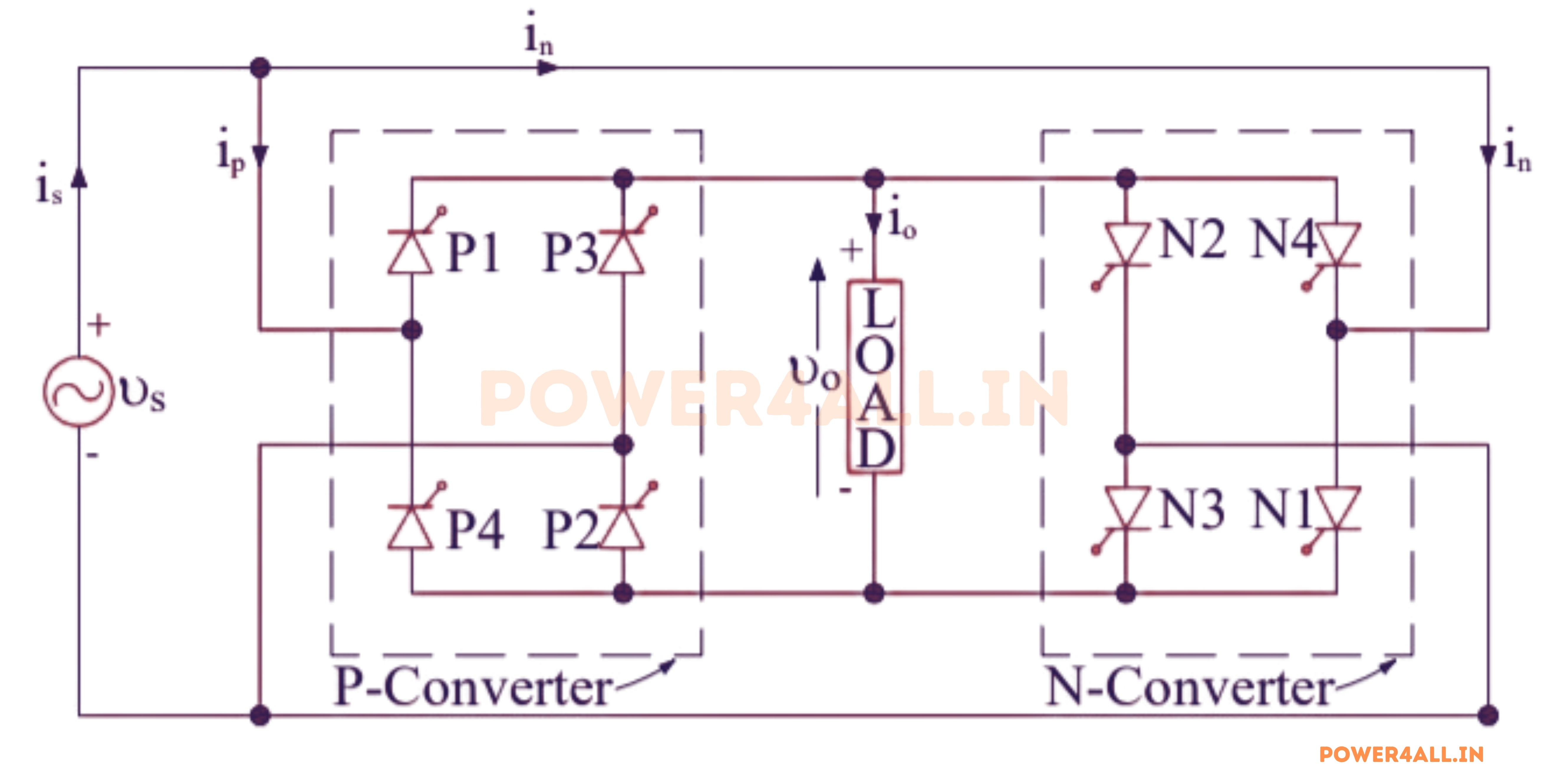
The system is composed of interconnected controlled rectifiers arranged in a back-to-back configuration. The output voltage and frequency are adjustable by manipulating the firing angles of the rectifiers. Depending on the rectifier connection, the structure may feature either a half-wave or full-wave bridge.
The apparatus comprises two fully controlled bridge thyristors, each of which incorporates four thyristors. These bridges are interconnected in opposing directions (back to back), enabling the production of both positive and negative voltages, as illustrated in the accompanying figure. Both of these bridges are energized by a single-phase, 50 Hz AC power supply.
The positive group converter of Bridge 1 supplies the load current during the positive half of the output cycle, while the negative group converter of Bridge 2 supplies the load current during the negative half of the output cycle.
Working Single Phase to Single Phase Cycloconverter
Working Single Phase to Single Phase Cycloconverter
When the forward biased thyristors (P1 and P2) are simultaneously activated at ωt = 0, the load voltage exhibits a positive polarity, with terminal "A" exhibiting positivity in relation to terminal "O". Consequently, the load voltage tracks the positive envelope of the supply voltage.
At the time ωt1, the conducting thyristors P1 and P2 undergo force commutation, leading to the activation of the forward-biased thyristor pair N1 and N2. Upon the activation of N1 and N2, the load voltage assumes a negative state with terminal "A" becoming negative relative to terminal "O".
Consequently, the load voltage aligns with the negative envelope of the input supply voltage. Subsequently, at time ωt2, the thyristor pairs N1 and N2 undergo force commutation, facilitating the firing of the forward -biased thyristors P1 and P2 for activation.
Consequently, the load voltage becomes positive, following the positive envelope of the input supply. Notably, the switching frequency is contingent upon the required output frequency, such that a higher required output frequency corresponds to an increased thyristor switching frequency.
Upon reaching ωt = π, the thyristor pairs (P1 & P2) and (N1 & N2) transition into a state of reverse bias, while the pairs (P3 & P4) and (N3 & N4) become forward biased. Subsequently, the forward biased thyristors can be activated and force commutated from ωt = π to ωt = 2π, inducing a high frequency turning ON and force commutation of all pairs, resulting in a high frequency output voltage at the load terminal.
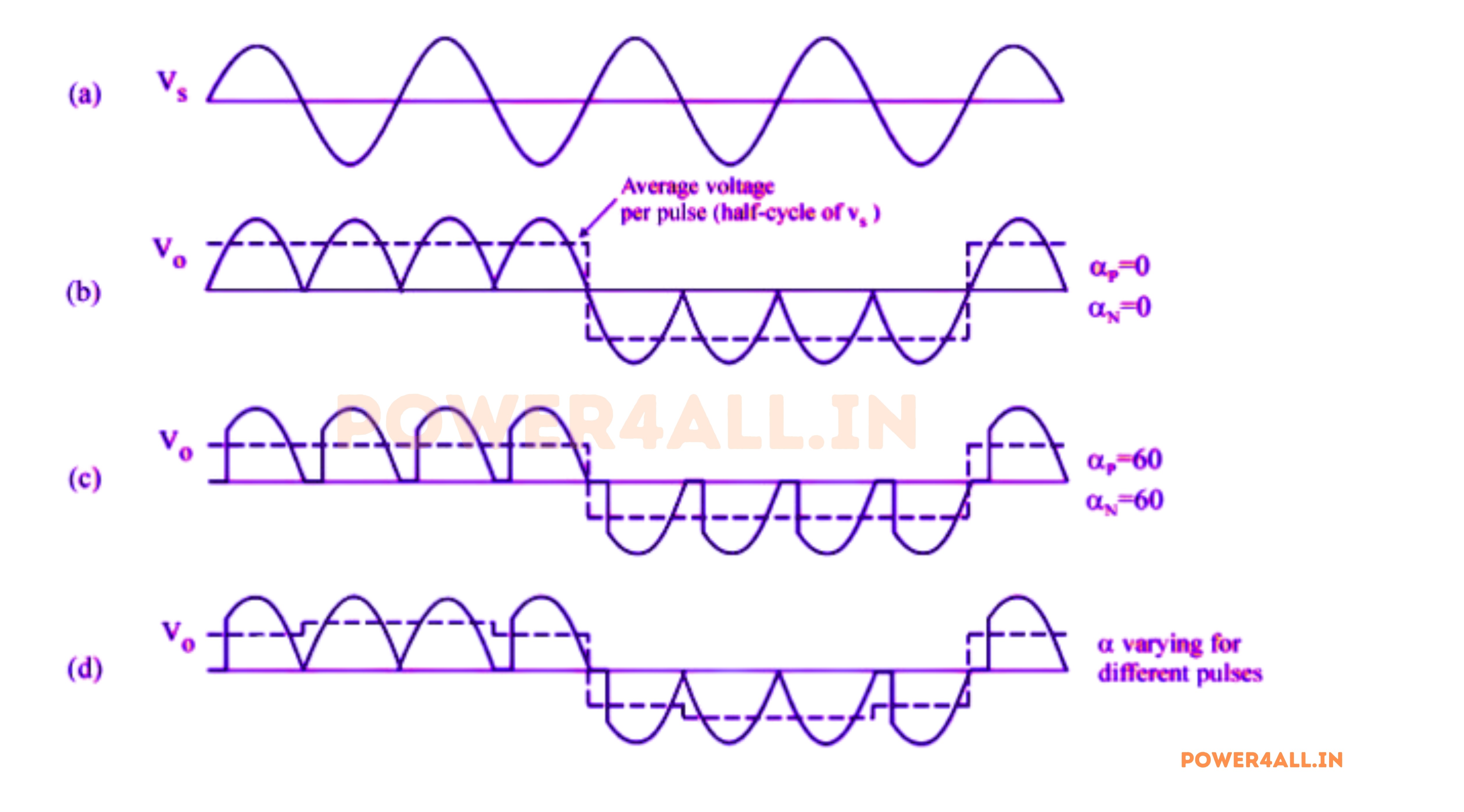
Waveform of Single phase to Single phase Cycloconverter
Waveform of Single phase to Single phase Cycloconverter
Advantages of Single-Phase to Single-Phase Cycloconverter
- Direct Frequency Control: It can change the frequency of the AC supply directly, making it easy to get the exact output frequency you need for your application.
- No Intermediate DC Link: The circuit does not need to convert AC to DC and back to AC, which keeps the design simple and efficient.
- Variable Output: Both the output voltage and frequency can be adjusted over a wide range, which is helpful for speed control of AC motors and other loads.
- Compact Design: Since it doesn’t require large energy storage components like capacitors or inductors, the overall system can be more compact.
- Good for Low-Power Loads: Especially suitable for small or medium loads where precise frequency and voltage control is needed.
- Bidirectional Power Flow: It can allow power to flow in both directions, which is useful in some control and braking applications.
Disadvantages of Single-Phase to Single-Phase Cycloconverter
- High Harmonic Content: The output waveform contains significant harmonics, which can cause extra heating and noise in motors or may require additional filtering.
- Limited Output Frequency: The output frequency is usually limited to less than half (often one-third or one-fourth) of the input frequency for proper operation and waveform quality.
- Complex Firing Control: The timing and control of the thyristors or SCRs must be precise, so the control circuit can be complicated.
- Not Suitable for High Power: For large industrial loads, three-phase cycloconverters are preferred. Single-phase types are best for small and medium applications.
- Possible Commutation Problems: With inductive loads, current may continue to flow after the voltage reverses, which can complicate switching and commutation.
- Low Power Factor: The circuit may operate at a lower power factor, especially at low output frequencies.
- Requires Careful Design: To avoid short circuits and ensure safe operation, only one converter group (positive or negative) should conduct at a time.
Applications of Single-Phase to Single-Phase Cycloconverter
- Speed Control of Single-Phase AC Motors: Used in fans, small pumps, and other equipment where variable speed is needed.
- Induction Heating: Supplies adjustable-frequency AC for heating metals in industrial and laboratory settings.
- Testing and Research: Provides a variable-frequency AC source for testing electrical devices and components.
- Low-Frequency Power Supplies: Used in applications that require AC at frequencies lower than the standard mains supply, such as special lighting or laboratory experiments.
- Simulators and Educational Trainers: Helps demonstrate frequency conversion and waveform shaping in academic labs.
- Small Variable-Frequency Drives: Suitable for driving small single-phase motors in appliances and automation systems.
Single-Phase to Single-Phase Cycloconverter FAQs
Usually, only one group conducts at a time, and the other is blocked, preventing current from circulating between groups.