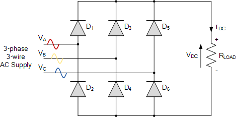
What is a three-phase full-wave (6-pulse) bridge rectifier?
A three-phase full-wave bridge rectifier uses six diodes arranged as two groups: three diodes with a common cathode form the positive rail (each follows its phase when it is the most positive), and three with a common anode form the negative rail (each follows its phase when it is the most negative). The load therefore sees the difference between the highest and lowest phase voltages — the upper envelope of the six line-to-line waveforms. A commutation happens every 60°, giving six pulses per cycle and an exceptionally smooth DC. This is the workhorse of industrial rectification and the input stage of almost every large drive, UPS and DC power supply.
Output voltage, PIV & ripple
Here Vm is the peak of each phase (line-to-neutral) voltage, so the peak line-to-line voltage is √3·Vm. The ripple factor is only about 0.042 — a tiny fraction of a single-phase rectifier — and the ripple sits at six times the supply frequency (300 Hz on a 50 Hz supply), so the bridge needs almost no output filtering. Each diode blocks the full line-to-line peak, PIV = √3·Vm, and unlike the half-wave rectifier there is no DC component in the transformer windings.
Advanced options in this simulator
- Diode model: add a forward drop
V_fand on-resistanceR_on; the bridge conducts through two diodes in series, so the total drop is2·V_f + 2·R_on·i. The accuracy check stays locked to the ideal envelope. - Transformer: a turns ratio scales the phase voltage that reaches the bridge.
- Load configuration: resistive, inductive (R-L) or with a back-EMF (R-L-E, e.g. a DC motor or battery).
- Filter & protection: a series-L, shunt-C or LC output filter, an optional RC snubber, and a live protection-margin check of the diode PIV and average current against the ratings you enter.
- Phase sequence & imbalance: swap the sequence or unbalance the phases and watch the ripple and harmonics change.
- Harmonic spectrum analysis: a real FFT of the output voltage (6th, 12th, 18th …) or the AC line current (5th, 7th, 11th, 13th …) with the ripple / THD figure.
- Export & capture: download the full waveform data as CSV, a text report, or a PNG screenshot of the scope.
6-pulse bridge vs 3-pulse half-wave
| Feature | 3φ half-wave (3-pulse) | 3φ bridge (6-pulse) |
|---|---|---|
| Diodes | 3 | 6 |
| Average voltage | 3√3·Vm/2π = 0.827·Vm | 3√3·Vm/π = 1.654·Vm |
| Ripple frequency | 3f | 6f |
| Ripple factor | ≈ 0.18 | ≈ 0.042 |
| PIV | √3·Vm | √3·Vm |
| Transformer DC | Yes | No |
See the three-phase half-wave rectifier simulator for the 3-pulse version, or the three-phase full-wave controlled rectifier for the phase-controlled (SCR) bridge.
Applications
High-power DC supplies, DC-motor and traction drives, electrolysis and electroplating plant, UPS front-ends, and the diode front-end of most AC and DC variable-speed drives. When adjustable output or regeneration is needed, the six diodes are replaced by six thyristors to make a fully-controlled bridge.
Frequently asked questions
What is the average output voltage of a 6-pulse bridge rectifier?
Vdc = 3√3·Vm/π ≈ 1.654·Vm and Vrms ≈ 1.6554·Vm, where Vm is the phase (line-to-neutral) peak. This is double the three-phase half-wave rectifier.
What is its ripple frequency and ripple factor?
Ripple frequency is 6f (300 Hz at 50 Hz) and the ripple factor is only about 0.042 — so almost no filtering is required.
What is the PIV of each diode?
PIV = √3·Vm — the peak line-to-line voltage.
Which harmonics appear?
The output-voltage ripple has harmonics at multiples of 6× the supply frequency (6th, 12th, 18th …); the AC line current has characteristic harmonics of order 6k±1 (5th, 7th, 11th, 13th …). Toggle the spectrum panel between voltage and line current.
Why is the 6-pulse bridge so widely used?
Double the DC of a 3-pulse rectifier, very low ripple at 6f, no DC in the transformer and good device utilisation — making it the standard for high-power rectification.