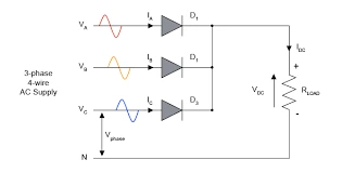
What is a three-phase half-wave rectifier?
A three-phase half-wave (3-pulse) rectifier connects one diode to each phase, with all three cathodes joined at a common point that feeds the load; the neutral is the return. At any instant only the diode fed by the most positive phase conducts, so the output voltage traces the upper envelope of the three phase voltages. Because three diodes share the cycle, each conducts for 120° and the output has three humps per cycle — far smoother than a single-phase rectifier.
Output voltage, PIV & ripple
Here Vm is the peak of each phase (line-to-neutral) voltage. The ripple factor is only about 0.18 — roughly a seventh of a single-phase half-wave rectifier — and the ripple sits at three times the supply frequency (150 Hz on a 50 Hz supply), so very little filtering is needed. Each diode must block the full line-to-line peak, PIV = √3·Vm.
Advanced options in this simulator
- Diode model: add a forward voltage drop
V_fand on-resistanceR_onto see the real (slightly lower, slightly drooping) output. - Transformer: a turns ratio scales the phase voltage that reaches the diodes.
- Load configuration: resistive, inductive (R-L) or with a back-EMF (R-L-E, e.g. a DC motor or battery).
- Filter & protection: a series-L, shunt-C or LC output filter, an optional RC snubber, and a live protection margin check of the diode PIV and average current against the ratings you enter.
- Phase sequence & imbalance: swap the sequence or unbalance the phases and watch the ripple and harmonics change.
- Harmonic spectrum analysis: a real FFT of the output voltage with the ripple/THD figure.
Three-phase vs single-phase
| Feature | 1φ half-wave | 3φ half-wave (3-pulse) |
|---|---|---|
| Diodes | 1 | 3 |
| Average voltage | Vm/π = 0.318·Vm | 3√3·Vm/2π = 0.827·Vm |
| Ripple frequency | f | 3f |
| Ripple factor | 1.21 | ≈ 0.18 |
| PIV | Vm | √3·Vm |
Applications
Medium-power DC supplies, battery charging, DC motor drives and any load fed from a three-phase supply where low ripple and good utilisation matter. For the lowest ripple and best transformer utilisation, the three-phase full (6-pulse) bridge is preferred.
Frequently asked questions
What is the average output voltage of a three-phase half-wave rectifier?
Vdc = 3√3·Vm/2π ≈ 0.827·Vm and Vrms = Vm·√(½ + 3√3/8π) ≈ 0.8407·Vm, where Vm is the phase (line-to-neutral) peak.
What is its ripple frequency and ripple factor?
Ripple frequency is 3f (150 Hz at 50 Hz) and the ripple factor is only about 0.18.
What is the PIV of each diode?
PIV = √3·Vm — the peak line-to-line voltage.
What does the harmonic spectrum show?
An FFT of the output: the DC value plus harmonics, which for a 3-pulse rectifier appear only at multiples of 3× the supply frequency. The ripple/THD figure is their combined size relative to the DC.
Why is a three-phase rectifier better than single-phase?
Higher average voltage, a ripple frequency of 3f instead of f, and a far smaller ripple factor — so it needs much less filtering.