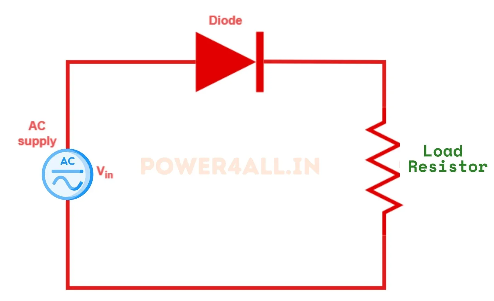
What is a single-phase half-wave uncontrolled rectifier?
A single-phase half-wave uncontrolled rectifier is the simplest AC-to-DC converter: a single diode in series with the load. The diode conducts automatically during each positive half-cycle (when it is forward biased) and blocks during the negative half-cycle. The result is a pulsating DC made of the positive humps of the supply — "uncontrolled" because a plain diode has no gate, so the output cannot be adjusted.
Output voltage & current equations (resistive load)
The average load current is Idc = Vm / (π·R) and the RMS current is Irms = Vm / (2R). This simulator does not plug numbers into these formulas — it integrates the real circuit through the diode's conduction states and measures Vdc and Vrms from the samples, then compares them to the equations above in the accuracy panel.
Performance figures (resistive load)
| Average voltage Vdc | Vm/π = 0.318·Vm |
|---|---|
| RMS voltage Vrms | Vm/2 = 0.500·Vm |
| Form factor | Vrms/Vdc = π/2 ≈ 1.571 |
| Ripple factor | √(FF² − 1) ≈ 1.21 |
| Rectification efficiency | ≈ 40.6 % |
| Peak inverse voltage (PIV) | Vm |
Inductive load & the freewheeling diode
With an R-L load and no freewheeling diode, the inductor's stored energy keeps the diode conducting past 180° into the negative half-cycle until the current reaches zero (the extinction angle β). This drags the output negative and lowers the average voltage. Adding a freewheeling diode across the load gives the current an alternative path when the supply goes negative: the output is clamped to zero, the main diode turns off at 180°, ripple falls and the average voltage rises back to Vm/π. Toggle it in the simulator to compare.
Adding an output filter
Half-wave output has very high ripple (ripple factor ≈ 1.21). A series inductor smooths the load current, a shunt capacitor holds the voltage near the peak and cuts ripple, and an LC filter combines both. The simulator integrates the real filter differential equations, so the Load ripple reading and the smoothed v₀ trace are physically exact — try the Capacitor filter preset.
Advanced options in this simulator
- Diode model: add a forward voltage drop
V_fand on-resistanceR_onto see the real (slightly lower, drooping) output — while the accuracy check stays locked to the idealVm/πenvelope. - Transformer: a turns ratio scales the peak voltage
Vmapplied to the diode. - Filter & protection: a series-L, shunt-C or LC output filter, an optional RC snubber, and a live protection-margin check of the diode PIV and average current against the ratings you enter.
- Harmonic spectrum analysis: a real FFT of the output voltage with the ripple / THD figure.
Controlled vs uncontrolled
| Feature | Uncontrolled (diode) | Controlled (SCR) |
|---|---|---|
| Device | Diode | Thyristor (SCR) |
| Output control | Fixed | Adjustable via firing angle α |
| Average voltage | Vm/π | (Vm/2π)(1 + cos α) |
| Conduction start | Automatic at ωt = 0 | Delayed to ωt = α |
Explore the adjustable version in the half-wave controlled rectifier simulator.
Advantages, disadvantages & applications
Advantages: extremely simple and cheap (one diode), easy to build. Disadvantages: uses only one half-cycle, so high ripple, low efficiency (~40.6%), poor transformer utilisation and a DC component in the supply current that can saturate transformer cores. Applications: low-power battery chargers, small signal-level supplies, LED indicators, and as a fundamental teaching example. For real power supplies a full-wave or bridge rectifier is used.
Frequently asked questions
What is the average output voltage of a half-wave rectifier?
For a resistive load, Vdc = Vm/π ≈ 0.318·Vm and Vrms = Vm/2, where Vm is the peak supply voltage.
What is the ripple factor of a half-wave rectifier?
About 1.21 for a resistive load — the AC (ripple) content is larger than the DC content, which is why heavy filtering is needed.
What is the rectification efficiency?
The maximum efficiency of a single-phase half-wave rectifier is about 40.6 %, because only one half of each cycle is used.
What is the diode's peak inverse voltage (PIV)?
For a resistive load the PIV equals the peak supply voltage, PIV = Vm. The protection-margin readouts compare this PIV and the diode's average current against the ratings you enter, and turn amber if the margin drops below 1.3×.
What does the harmonic spectrum show?
An FFT of the output voltage: a large DC term plus a strong ripple at the fundamental (1×) and its harmonics, giving a high THD of about 121% of the DC — the numeric reason half-wave output needs heavy filtering.
How is this different from a controlled rectifier?
An uncontrolled rectifier uses a diode that conducts automatically, so the output is fixed. A controlled rectifier uses a thyristor whose firing angle can delay conduction, giving an adjustable DC output.