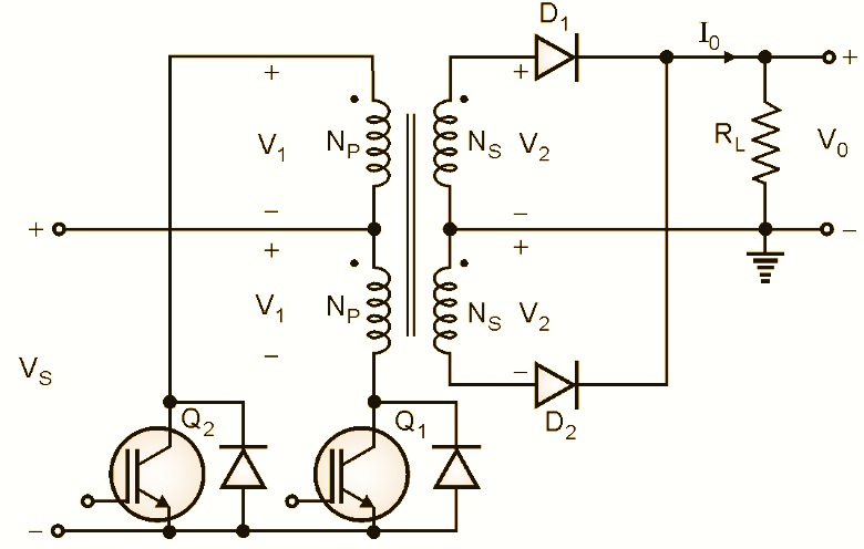
What is a push-pull converter?
A push-pull converter is an isolated DC-DC topology in which two switches alternately drive a center-tapped transformer primary. On one half-cycle the first switch pulls current through the upper half-winding; on the next, the second switch pushes current through the lower half — hence "push-pull." The secondary is full-wave rectified and feeds a buck-like LC output filter. Because there are two power pulses per switching period, the output voltage is twice that of a single-switch forward stage and the output ripple is at twice the switching frequency, allowing a smaller filter.
How it works
- Switch 1 ON (0 → D·T): the upper primary sees Vs; the secondary applies
n·Vsto the LC filter and the output inductor current ramps up. - Dead-time: both switches off; the rectifier freewheels (node = 0) and the inductor current ramps down.
- Switch 2 ON (T/2 → T/2+D·T): the lower primary sees Vs in the opposite polarity; the full-wave rectifier again applies
n·Vs— a second power pulse. - Dead-time again to the end of the period.
Key equations
This simulator numerically integrates the real push-pull switching circuit — two power pulses per period into the output LC, plus the transformer magnetizing current — to steady state, then compares the measured Vo and ripple to the equations above in the accuracy panel.
Flux imbalance & staircase saturation (topic-specific)
The push-pull's Achilles' heel is flux imbalance. If the two switches do not apply exactly equal volt-seconds — through unequal on-times, unequal Rds(on) or asymmetric gate drive — the transformer core accumulates a small DC flux each cycle. That flux staircases toward one saturation rail; once the core saturates the magnetizing current spikes and can destroy the switches. Real designs prevent it with current-mode control or a small series blocking capacitor. Use the volt-second mismatch slider and watch the magnetizing-current trace develop a growing DC offset and trip the saturation alarm.
Switch voltage stress
When one switch conducts, autotransformer action places roughly 2·Vs across the off switch (plus leakage ringing). This is the main disadvantage versus the half-bridge, whose switches only block Vs — so the push-pull is preferred at low input voltages (12/24/48 V) where 2·Vs is still comfortable.
Advanced options in this simulator
- Two-switch drive with dead-time: duty limited to 0.5 per switch, two power pulses per period.
- Flux-imbalance analyzer: introduce a volt-second mismatch and watch the DC flux walk and saturation alarm.
- 2·Vs switch-stress meter: live off-state switch voltage.
- Device model: MOSFET Rds(on), diode Vf, inductor DCR and capacitor ESR; the accuracy check stays locked to the ideal Vo.
- Ripple spectrum: a real FFT showing the dominant ripple at twice fsw.
- Export & capture: CSV data, a text report, or a PNG screenshot of the scope.
The six isolated DC-DC converters
| Converter | Switches | Ideal Vo | Switch stress |
|---|---|---|---|
| Flyback | 1 | n·Vs·D/(1−D) | Vs + Vo/n |
| Forward | 1 | n·Vs·D | Vs·(1+Np/Nr) |
| Push-Pull | 2 (center-tap) | 2·n·Vs·D | 2·Vs |
| Half-Bridge | 2 + split caps | n·Vs·D | Vs |
| Full-Bridge | 4 | 2·n·Vs·D | Vs |
| Phase-Shifted FB | 4 (ZVS) | 2·n·Vs·Deff | Vs |
Explore the others: Flyback, Forward, Half-Bridge, Full-Bridge and Phase-Shifted Full-Bridge simulators. For the full theory see the Push-Pull converter tutorial.
Applications
Low-voltage, medium-power isolated supplies: 12/24/48 V battery and telecom inputs, automotive DC-DC, inverter front-ends and any design that benefits from a common-ground two-switch drive and good transformer utilisation.
Frequently asked questions
What is the output voltage of a push-pull converter?
In CCM the ideal output is Vo = 2·n·Vs·D, where D is the duty of each switch (≤0.5). Two power pulses per period double the output versus a single forward stage.
Why is the duty limited to 0.5?
Each switch conducts for at most half the period; overlapping conduction would short the center-tapped primary (shoot-through). A dead-time separates the two intervals.
What is flux imbalance / staircase saturation?
Unequal volt-seconds between the two switches leave a small DC flux each cycle. It staircases up until the core saturates. Current-mode control or a series blocking capacitor prevents it — the simulator lets you provoke it with the mismatch slider.
What is the switch voltage stress?
About 2·Vs due to autotransformer action, plus leakage ringing — the main reason push-pull is used at low input voltages.
Why is the output ripple at twice the switching frequency?
Two power pulses are delivered per switching period, so the LC filter sees a ripple fundamental at 2·fsw, allowing a smaller filter than a single-pulse topology.