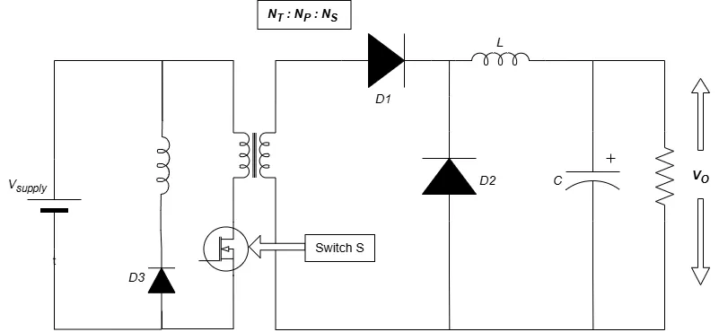
What is a forward converter?
A forward converter is an isolated, buck-derived DC-DC (SMPS) topology. Like a flyback it uses a transformer for isolation, but unlike a flyback it transfers energy directly to the output during the on-time rather than storing it. A single primary MOSFET drives the transformer; the secondary has a forward rectifier diode, a freewheel diode and an output LC filter — essentially an isolated buck stage. Because the transformer only carries flux in one direction, it needs a reset winding (or active-clamp) to return the magnetizing flux to zero every cycle.
How it works — the two switching states
- Switch ON (0 → D·T): the primary sees Vs; the secondary forward diode conducts and applies
n·Vsto the LC filter, sodi_Lo/dt = (n·Vs − Vo)/Lo. Meanwhile the magnetizing current ramps up asdi_m/dt = Vs/Lm. - Switch OFF (D·T → T): the forward diode blocks, the freewheel diode carries the inductor current (node = 0), and the reset winding drives the magnetizing current back to zero as
di_m/dt = −Vs·(Np/Nr)/Lm.
Key equations
This simulator does not plug numbers into these formulas — it numerically integrates the real forward switching circuit (secondary node, output inductor, capacitor and the magnetizing reset) to steady state, then measures Vo, the ripple and the losses and compares them to the equations above in the accuracy panel.
Core reset & the maximum duty cycle (topic-specific)
The magnetizing flux built up during the on-time must be reset every cycle. A tertiary reset winding of ratio Nr/Np returns that energy to the input and forces the magnetizing current back to zero. The reset takes as long as the build-up scaled by Nr/Np, so the duty cycle is limited to Dmax = 1/(1+Nr/Np) — for an equal-turns winding that is 0.5. Exceed it and the flux staircases up cycle after cycle until the core saturates. A reset winding with fewer turns resets faster (higher Dmax) but makes the switch block a higher voltage Vs·(1+Np/Nr). The simulator's core-reset panel shows this limit live and raises a saturation alarm.
Continuous vs discontinuous conduction (CCM / DCM)
The output LC behaves like a buck: in CCM the inductor current never falls to zero and Vo = n·Vs·D holds; at light load or with a small inductor it enters DCM and the output rises above n·Vs·D. The boundary is the critical inductance Lc = (1−D)·R/(2·fsw).
Advanced options in this simulator
- Turns ratio & reset ratio: set the output voltage (n) and the reset behaviour / Dmax / switch stress (Nr/Np) independently.
- Core-reset visualizer & saturation alarm: watch the magnetizing current reset and get warned when D exceeds Dmax.
- Output LC filter: buck-like ripple and CCM/DCM behaviour.
- Device model: MOSFET Rds(on), diode Vf, inductor DCR and capacitor ESR; the accuracy check stays locked to the ideal Vo.
- Ripple spectrum: a real FFT of the output voltage or the inductor current at multiples of fsw.
- Export & capture: CSV data, a text report, or a PNG screenshot of the scope.
The six isolated DC-DC converters
| Converter | Switches | Ideal Vo | Filter |
|---|---|---|---|
| Flyback | 1 | n·Vs·D/(1−D) | Output cap only |
| Forward | 1 | n·Vs·D | LC filter |
| Push-Pull | 2 (center-tap) | 2·n·Vs·D | LC filter |
| Half-Bridge | 2 + split caps | n·Vs·D | LC filter |
| Full-Bridge | 4 | 2·n·Vs·D | LC filter |
| Phase-Shifted FB | 4 (ZVS) | 2·n·Vs·Deff | LC filter |
Explore the others: Flyback, Push-Pull, Half-Bridge, Full-Bridge and Phase-Shifted Full-Bridge simulators. For the full theory see the Forward converter tutorial.
Applications
Telecom 48 V rectifier/bus converters, server and industrial supplies, medium-power isolated rails (roughly 50–500 W), and any application needing lower output ripple than a flyback with direct power transfer.
Frequently asked questions
What is the output voltage of a forward converter?
In CCM the ideal output is Vo = n·Vs·D with n = Ns/Np. It behaves like an isolated buck — power is transferred directly during the on-time into an LC filter.
Why does it need a reset winding?
The magnetizing flux built up during the on-time must be reset to zero every cycle. A reset winding returns that energy to the input; without it the core would walk into saturation.
What is the maximum duty cycle?
Dmax = 1/(1+Nr/Np). For an equal-turns reset winding that is 0.5. Above it the flux cannot reset and the transformer saturates — the simulator flags this.
How is a forward different from a flyback?
A flyback stores energy and delivers it during the off-time (output cap only, n·Vs·D/(1−D)). A forward transfers energy during the on-time through an LC filter (n·Vs·D) and needs a reset winding.
What sets the switch voltage stress?
During reset the MOSFET blocks Vs·(1+Np/Nr) — 2·Vs for an equal-turns reset winding. Fewer reset turns raise Dmax but also the switch voltage.