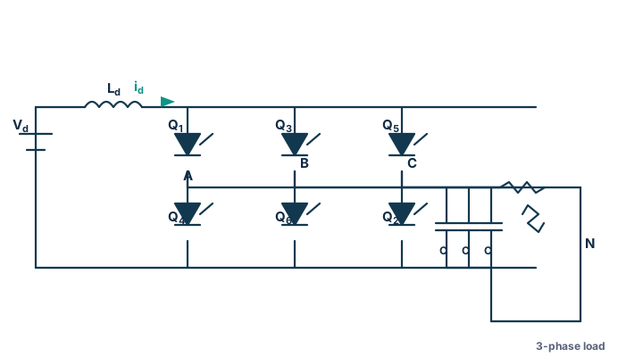
What is a three-phase current-source inverter (CSI)?
A current-source inverter (CSI) is the dual of the voltage-source inverter. Instead of a large capacitor holding the DC bus at a stiff voltage, a large DC-link inductor Ld holds the DC-link at a stiff current Id. The six-switch bridge then steers that constant current into the three output phases, so the inverter produces quasi-square currents (not voltages). Because the current must always have a path, exactly one upper and one lower device conduct at all times, and an output capacitor is mandatory to absorb the stepped current and give the load a smooth voltage.
Output current, fundamental and RMS
In 120° conduction each device conducts for 120° and the six are fired 60° apart in the order Q1→Q2→Q3→Q4→Q5→Q6. Each line current is a quasi-square wave: +Id for 120°, zero for 60°, −Id for 120°, zero for 60°:
This simulator forces the exact 120° switching current iinv = sk·Id and integrates the actual per-phase output network — star capacitor C in parallel with a star R-L load — with C·dv/dt = iinv − iload and L·diload/dt = v − R·iload, so every waveform, RMS and THD is exact.
Why the output capacitor and its resonance matter (topic-specific)
An inductive load cannot accept the sudden ±Id current steps, so the capacitor provides the missing path and filters the harmonics into a near-sinusoidal load voltage. The capacitor and load inductance form an LC filter with resonance fres = 1/(2π√(L·C)). The dominant inverter-current harmonics are the 5th and 7th; if the resonant order fres/f1 falls near them, the load voltage is amplified and heavily distorted. The resonance analyzer above computes fres, its harmonic order, and warns when a switching harmonic sits inside the resonant band.
CSI vs VSI — the duality
| Feature | Current-source inverter (CSI) | Voltage-source inverter (VSI) |
|---|---|---|
| DC link | Large inductor → stiff current Id | Large capacitor → stiff voltage Vdc |
| Output shape | Quasi-square current | Quasi-square voltage |
| Fundamental | I1 = √6·Id/π | VLL1 = √6·Vdc/π |
| Devices | Must block reverse voltage (series diode) | Need anti-parallel diode |
| Output filter | Capacitor (mandatory) | Optional / inductive |
| Fault behaviour | Inherently short-circuit safe | Needs shoot-through protection |
Compare with the three-phase 180° VSI, the three-phase 120° VSI, and the single-phase single-phase CSI.
Applications
Very large medium-voltage motor drives (fans, pumps, compressors), load-commutated inverters (LCI) for synchronous-machine starting, and STATCOM/current-fed systems where inherent short-circuit protection and robust devices are valued.
Frequently asked questions
What is a current-source inverter?
An inverter fed from a stiff DC current (large DC-link inductor) instead of a stiff DC voltage. It produces quasi-square output currents of amplitude ±Id and needs an output capacitor to give the load a smooth voltage.
What is the output current fundamental?
For 120° conduction the fundamental peak is 2√3·Id/π, fundamental RMS √6·Id/π ≈ 0.78·Id, total RMS √(2/3)·Id ≈ 0.816·Id and THD ≈ 31%.
Why must a CSI have an output capacitor?
The bridge forces a stepped, discontinuous current. An inductive load cannot accept instantaneous current changes, so the capacitor provides the path for the difference and filters the current into a near-sinusoidal load voltage.
How is a CSI different from a VSI?
The CSI is the dual of the VSI: inductor vs capacitor DC link, quasi-square current vs voltage, reverse-blocking devices vs anti-parallel diodes, mandatory output capacitor, and inherent short-circuit protection.