ZETA Converter
The primary function of a ZETA converter is to step up or step down voltage from a lower level to a higher level.
- Introduction
- DC-DC ZETA CONVERTER
- Circuit Diagram of ZETA Converter
- Working of ZETA Converter
- Mode I: When the MOSFET is ON
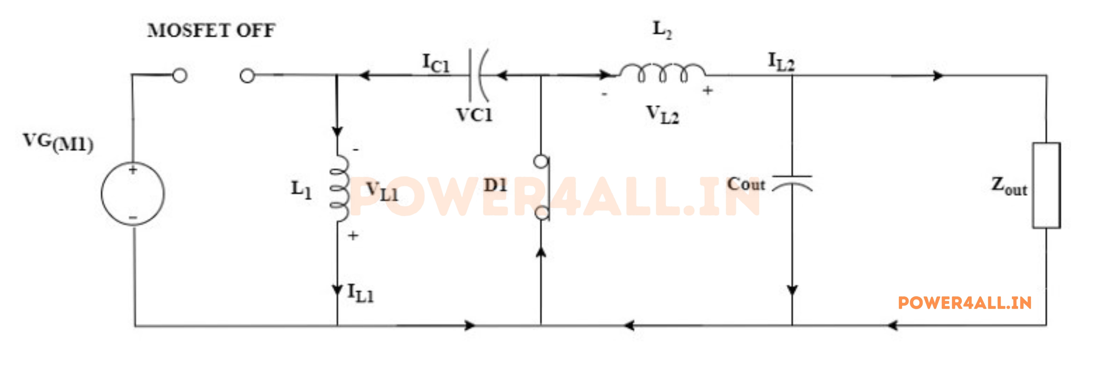
- Mode II: When the MOSFET is OFF
- Mode III: When the MOSFET is ON
- Mode IV: When the MOSFET is OFF
- Waveform of ZETA Converter
- Advantages of ZETA Converter
- Disadvantages of ZETA Converter
- Applications of ZETA Converter
- Conclusion
- Frequently Asked Questions About ZETA Converter – FAQs
- Related Topics
Introduction
When it comes to power conversion challenges, engineers often need solutions that can both step up and step down voltage while maintaining the same polarity. This is where the ZETA converter comes into play - a versatile DC-DC converter that offers the flexibility of both buck and boost operation without inverting the output. Though less commonly discussed than its cousins like buck or boost converters, the ZETA converter provides unique advantages that make it perfect for certain applications.
The ZETA converter shares some similarities with the SEPIC converter but with a different component arrangement. It uses an inductor-capacitor energy transfer mechanism that allows for smooth voltage conversion across a wide input range. What makes the ZETA particularly useful is its continuous output current characteristic, which helps reduce output ripple and improves performance when powering sensitive loads.
For battery-powered devices and systems with fluctuating input voltages, the ZETA converter offers a reliable solution. Its ability to maintain stable output regardless of whether the input voltage is above or below the target makes it ideal for applications like LED drivers, portable electronics, and renewable energy systems. While it might require a few more components than simpler topologies, the ZETA's performance benefits often outweigh this minor drawback, especially when clean, consistent power is essential.
DC-DC ZETA CONVERTER
The ZETA converter is a power electronic converter used in electrical power systems. It is a topology for DC-DC power conversion, meaning it is designed to convert electrical power from one DC voltage level to another. The ZETA converter stays an extension of the traditional buck-boost converter, providing some advantages regarding voltage regulation and efficiency.
Like other dc-to-dc converters, a ZETA converter achieves a regulated Output by exchanging energy intermediary capacitors and inductors. A switch controls the amount of energy exchanged by changing its duty cycle. Let us see the circuit design and operation of a ZETA converter.
The ZETA converter operates with a fixed input and regulated output, achieved through a buck converter for voltage reduction and a boost converter for voltage increase. An alternative topology involves the use of a Buck-Boost converter, providing adjustable voltage step-up or step-down capabilities. This converter uniquely yields output with an inverted polarity. The Cuk converter operates on a similar principle to the buck-boost converter, but with an output polarity reversal. Common DC-DC converters, such as the buck , boost , and buck-boost, consist of one capacitor, one inductor, one diode, and one semiconductor switch. Contrastingly, the Cuk converter architecture comprises two inductors, two capacitors, a diode, and a semiconductor switch, resulting in reduced voltage ripple on both input and output sides. A detailed exploration of the Cuk converter's topology will be presented in this section.
Circuit Diagram of ZETA Converter:
The figure shows the representation diagram of a ZETA converter. It involves two inductors, a capacitor, and a diode. The circuit of the ZETA converter is almost similar to a single-ended primary-inductor converter (SEPIC ) except in place of the diode in SEPIC, there is an inductor in the ZETA converter, and in the place of the second inductor in SEPIC, there is a diode in ZETA converterrter employs inductors and capacitors to achieve regulated output.
The circuit diagram for a typical ZETA converter is shown in the figure below.
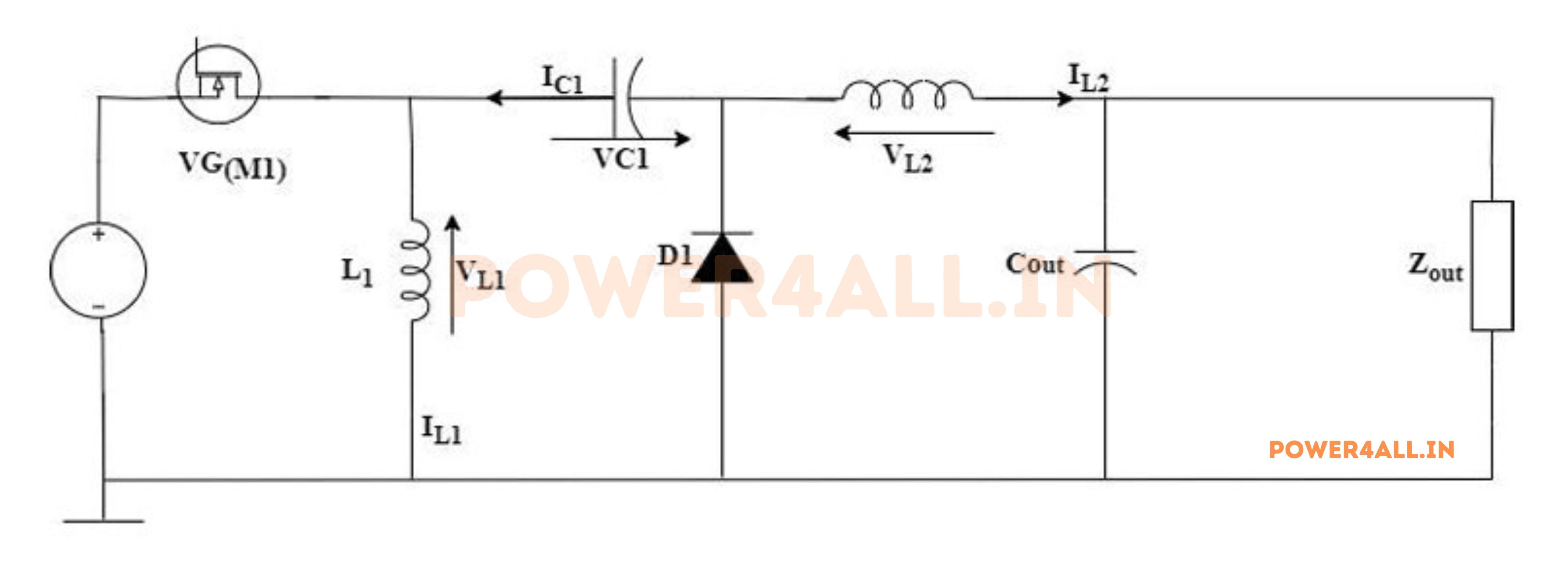
The capacitor C1 plays a crucial role in DC/DC converters as it connects the Input and Output sides while keeping them isolated from each other.
In such converters, a transistor (MOSFET, IGBT, or BJT) is typically utilized as the switch due to its low power loss, higher Input impedance, and easy-to-use driver circuitry. MOSFETs are the preferred choice for switching as they can be controlled by PWM pulses applied at the gate terminal and feedback taken from the Output, resulting in a desired regulated Output.
Working of ZETA Converter:
Initially, before starting the circuit operation, it is to be assumed that all the energy-storing components in the circuit i.e., inductors and capacitors, do not have any energy in them. To easily understand and simplify the working of the ZETA converter as well as the operation of the circuit is categorized into four modes.
here are two modes of operation of the ZETA converter. They are:
Mode I: When the MOSFET is ON
When MOSFET is triggered by applying a voltage higher than the threshold voltage at the gate terminal, the source current starts flowing through MOSFET, Inductor L1, and returns back to the source as revealed below.
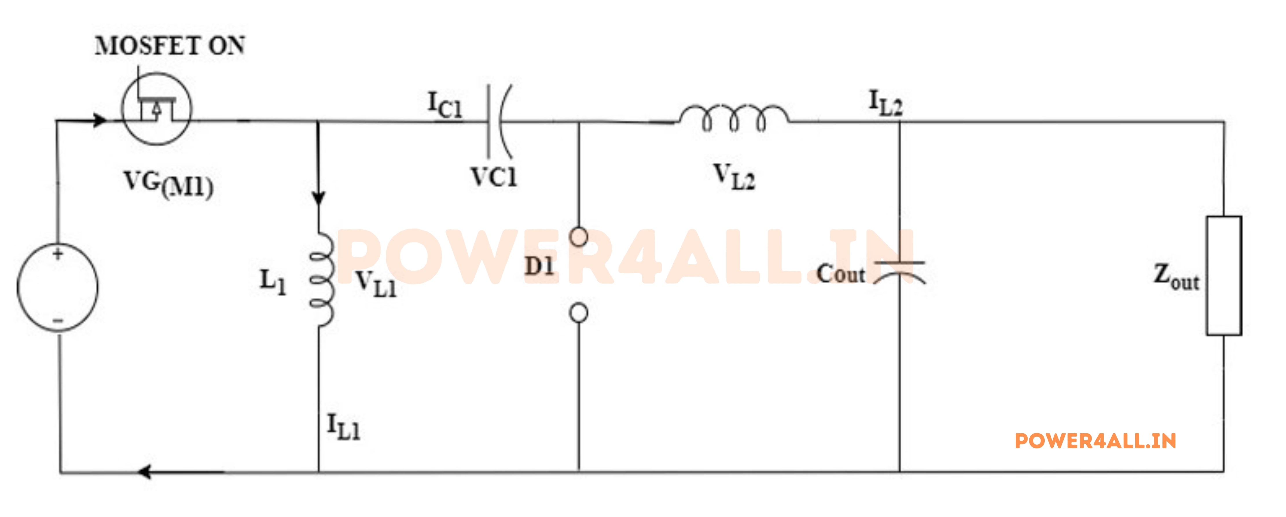
During this state, the flow of current through the inductor L1 makes it charge. Thus inductor L1 will store energy abounding by the source with the polarity as indicated above. No source current is supplied to the load in this mode.
Mode II: When the MOSFET is OFF
When MOSFET is kept turned OFF by removing its gate signal, the source current stops flowing through inductor L1. Since an inductor doesn’t allow a sudden change in current through it, the polarity of the inductor gets reversed according to Lenz law i.e., positive becomes negative, and negative becomes positive.
Now the inductor L1 twitches realizing its stockpiled energy with reversed polarity. Due to this diode will be forward biased and it permits the flow of inductor current through it. Thus, the energy from the inductor L1 will flow through the diode and to the capacitor C1 as shown below.
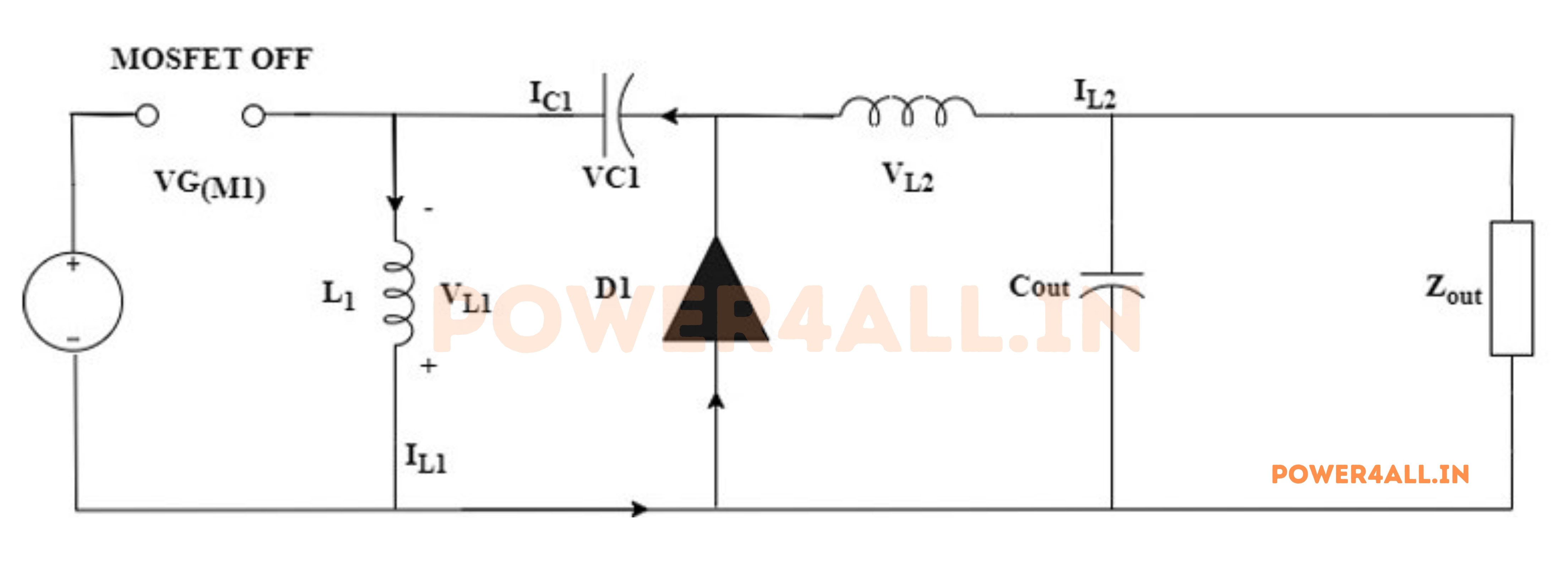
The series capacitor C1 kickstarts charging by the energy supplied by inductor L1. Here we can notice how a capacitor gets charged by DC, the current provided by the inductor is not constant DC which will be decreasing in nature. Thus, energy from the inductor L1 gets transferred to capacitor C1.
Upon activation of the MOSFET, the cycle initiates once more, leading to the charging of inductors L1 and L2 by the power source and capacitor C1, respectively. The operation of the SEPIC converter can be classified into either discontinuous conduction mode or continuous conduction mode, contingent on the reduction of current flow through the inductors to zero or not.
Mode III: When the MOSFET is ON
Again, when MOSFET is switched ON, the discharged inductor L1 gets charged by the source as seen in Mode-1. In the present state, the capacitor C1 that was previously charged begins discharging through the inductor L2, the load, and the source, and returns to the capacitor C1 in a closed circuit. This process can be visualized as shown below
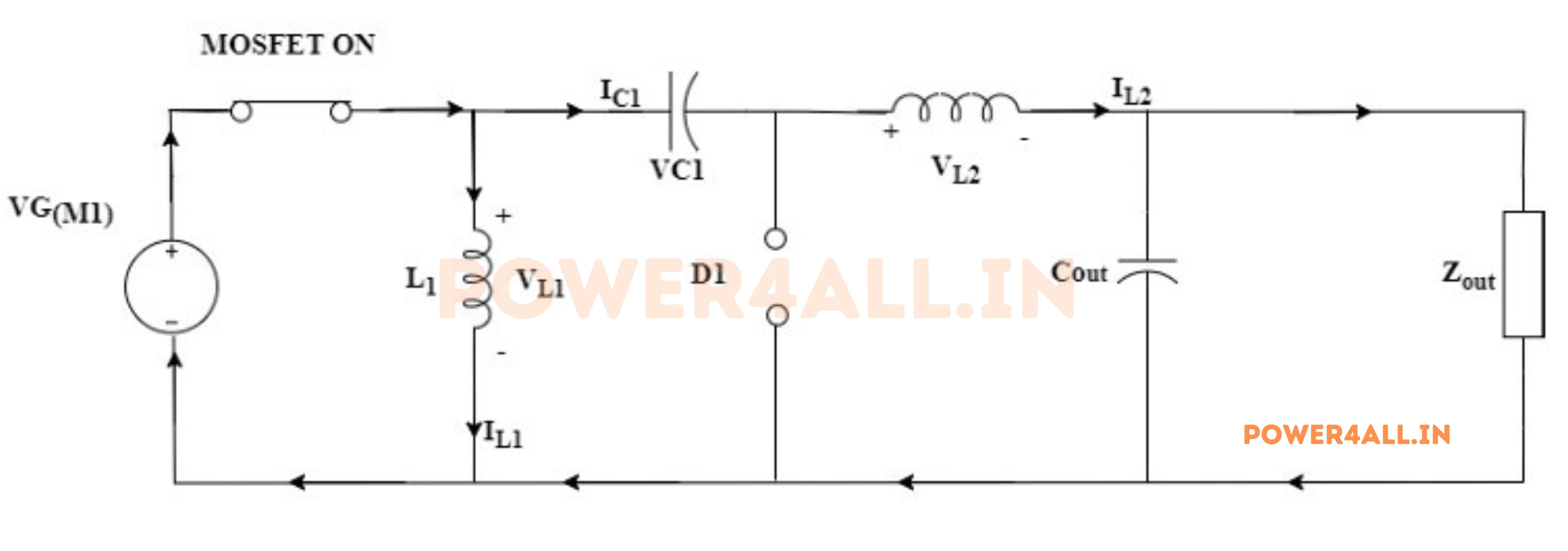
The energy stored in capacitor C1 will be transferred to the inductor L2 and the load connected to it. Thus, the load gets power in this mode and inductor L2 gets charged. The diode will remain in OFF-state due to reverse voltage.
Mode IV: When the MOSFET is OFF
Once MOSFET is turned OFF again, mode-2 will be repeated i.e., the inductor L1 backtracks its polarity and charges the discharged capacitor C1 through the diode. Along with it, inductor L2 also reverses its polarity due to a sudden change in current and begins providing power to the load through the same diode as revealed below.
In this way, the MOSFET is turned ON and OFF at a regular interval by applying and removing gate signals so that a regulated DC power will be supplied to the load. From the above four process modes of the Zeta converter, the conclusion is,
- -When the MOSFET is turned on, inductors L1 and L2 are charged by the source and capacitor C1, respectively.
- -When the MOSFET is in the OFF state, capacitor C1 charges through inductor L1, while inductor L2 supplies energy to the load.
- -The energy transfer between the inductors and capacitor occurs in a continuous cycle, ensuring a regulated output voltage.
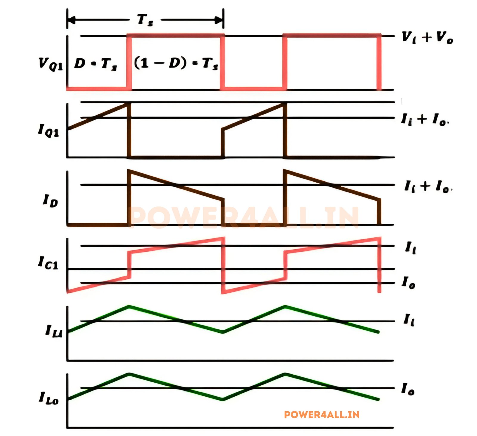
Waveform of ZETA Converter
The waveform of a ZETA converter is characterized by its distinct voltage and current profiles during the two operational modes. The following figure illustrates the voltage and current waveforms associated with the ZETA converter's operation.
Advantages of ZETA Converter
The ZETA converter offers several advantages, making it a popular choice in various applications:
- Non-Inverting Output:The ZETA converter provides a non-inverting output voltage, meaning the output voltage polarity is the same as the input voltage polarity.
- Flexible Voltage Range:It can both step up and step down the input voltage, providing a wide range of output voltage levels.
- Continuous Input and Output Currents:The input and output currents are continuous, which can be beneficial for applications requiring low ripple current.
- Improved Load Regulation:The ZETA converter can offer better load regulation compared to some other types of converters.
- Reduced Electromagnetic Interference (EMI):Due to its continuous input current, the ZETA converter typically generates less electromagnetic interference compared to converters with discontinuous input currents.
Disadvantages of ZETA Converter
While ZETA converters have many advantages, they also have some disadvantages:
- Complex Design:The ZETA converter circuit is more complex than basic buck or boost converters, involving more components such as inductors, capacitors, and switches, which can complicate design and analysis.
- Efficiency Concerns:Efficiency may be lower compared to other simpler converters because of the higher component count and the power losses associated with additional components.
- Component Stress:The converter can subject its components to higher stress levels, particularly during switching, which can affect reliability and lifespan if not properly managed.
- Control Complexity:The control strategy for ZETA converters can be more complex due to the need to manage both step-up and step-down operations and to ensure stability across a wide range of operating conditions.
- Cost:More components and a more complex design can lead to higher costs in both manufacturing and maintenance.
- Size:The ZETA converter may require more space on a PCB due to the additional components, which can be a disadvantage in size-constrained applications.
Applications of Zeta Converter
ZETA converters find applications in various fields, including:
- Battery-Powered Devices: Used in devices where voltage regulation is critical, such as in portable electronics.
- LED Drivers: Provides stable current and voltage for LED lighting applications.
- Renewable Energy Systems: Used in solar power systems to manage varying input voltages from solar panels.
- Electric Vehicles: Employed in electric and hybrid vehicles for efficient power conversion.
- Power Supply Units: Utilized in power supply designs where both step-up and step-down capabilities are needed.
Conclusion
In conclusion, the ZETA converter is a versatile and efficient DC-DC converter topology that can step up or step down voltage while maintaining the same polarity. Its unique design allows for continuous input and output currents, making it suitable for various applications, including battery-powered devices, LED drivers, and renewable energy systems. While it has some disadvantages, such as complexity and cost, its advantages often outweigh these drawbacks in specific use cases.