Three Phase Inverter - 180 Degree Conduction Mode
A three-phase inverter is designed to convert DC input into a three-phase AC output with full supply voltage, making it ideal for applications ranging from home power backup to industrial motor drives and solar energy systems.
- Introduction
- 180 Degree Conduction Mode
- Mode 1: 0° to 60° Operation
- Mode 2: 60° to 120° Operation
- Mode 3: 120° to 180° Operation
- Mode 4: 180° to 240° Operation
- Mode 5: 240° to 300° Operation
- Mode 6: 300° to 360° Operation
- Output Voltage Waveform of 180° Mode Inverter
- Advantages
- Disadvantages
- Applications
- Three Phase 180° Conduction Inverter FAQs
- Related Topics
Introduction
The following technical article provides an in-depth explanation of the operational principles of a three-phase power electronics inverter in the 180-degree conduction mode. A comprehensive analysis of the six thyristors' functionality and their associated waveforms is presented to facilitate a thorough understanding.
Three-phase inverters are predominantly employed in applications requiring medium to high power output. Modern iterations of these inverters are integral to the precise control of industrial drives, photovoltaic power generation, and motor drives, among other applications. Furthermore, these inverters offer advanced functionalities, including voltage and frequency control, enhancing their utility in diverse settings.
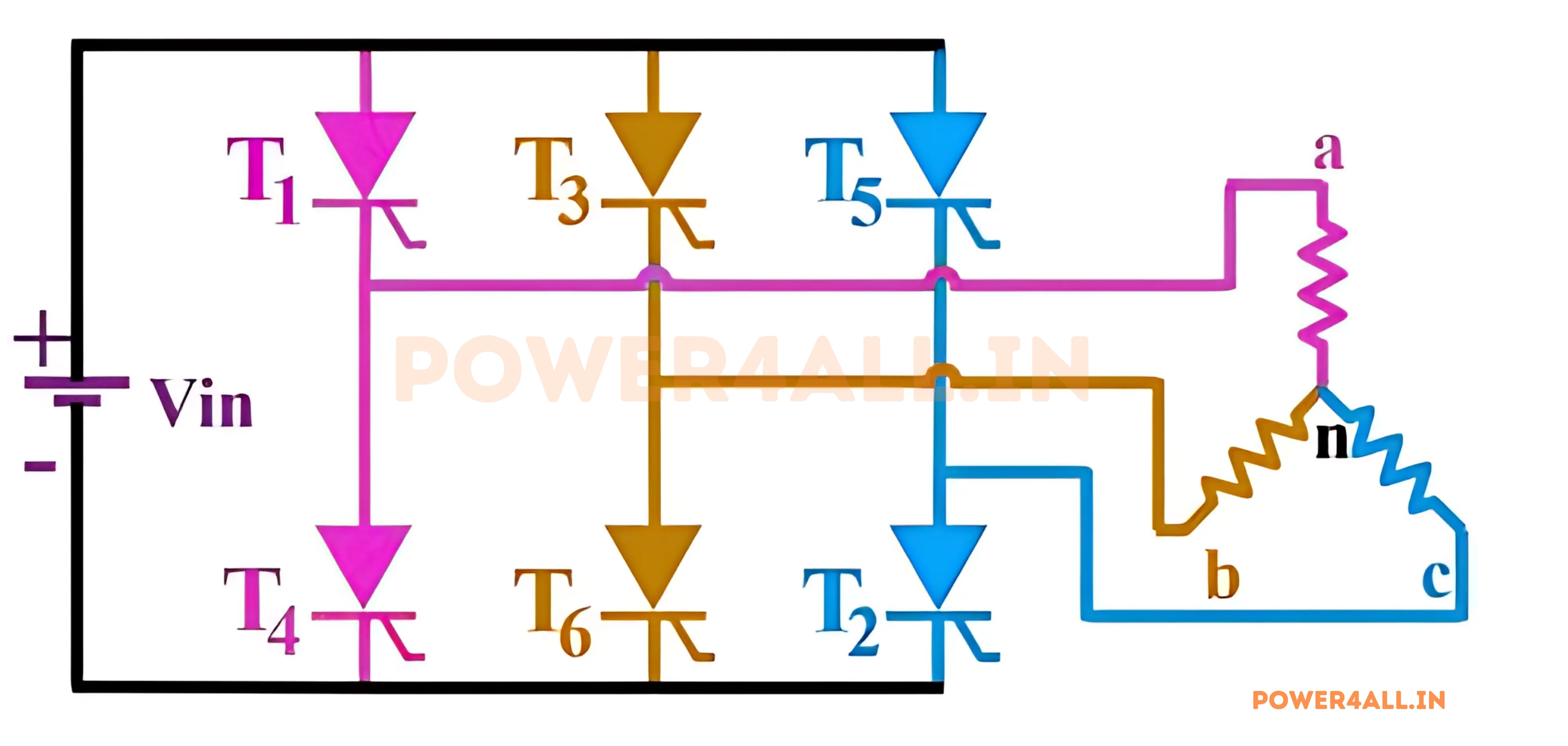
The three-phase inverter depicted in the figure above comprises six thyristor switches connected to a star-configured load with a neutral point (n) at the center. The nomenclature of the thyristors is derived from their operational characteristics, facilitating comprehension of their function.
The inverter comprises three legs, with each leg housing two thyristors. The upper leg contains odd-numbered thyristors, while the lower leg contains even-numbered ones. The star-connected load is tapped at the midpoint of each leg, where the two thyristors converge.
180 Degree Conduction Mode
The diagram presented below portrays the conduction period of various thyristors during each 60-degree interval within the complete 360-degree cycle. Consequently, six distinct modes of operation are discernible. It is noteworthy that each thyristor maintains conduction for 3*60 degrees, which equates to continuous operation for 180 degrees.
The thyristor pair on each leg is phase-shifted by 180 degrees, resulting in the activation of only one thyristor in each leg at any given time. Additionally, it is observed that each thyristor is phase-shifted by 120 degrees in relation to its immediate adjacent thyristor on the adjacent leg.
The thyristor pair on each leg is phase-shifted by 180 degrees, resulting in the activation of only one thyristor in each leg at any given time. Additionally, it is observed that each thyristor is phase-shifted by 120 degrees in relation to its immediate adjacent thyristor on the adjacent leg.
Figure Operating periods of the thyristors for every 60 degree in 180 degree conduction mode of three phase inverter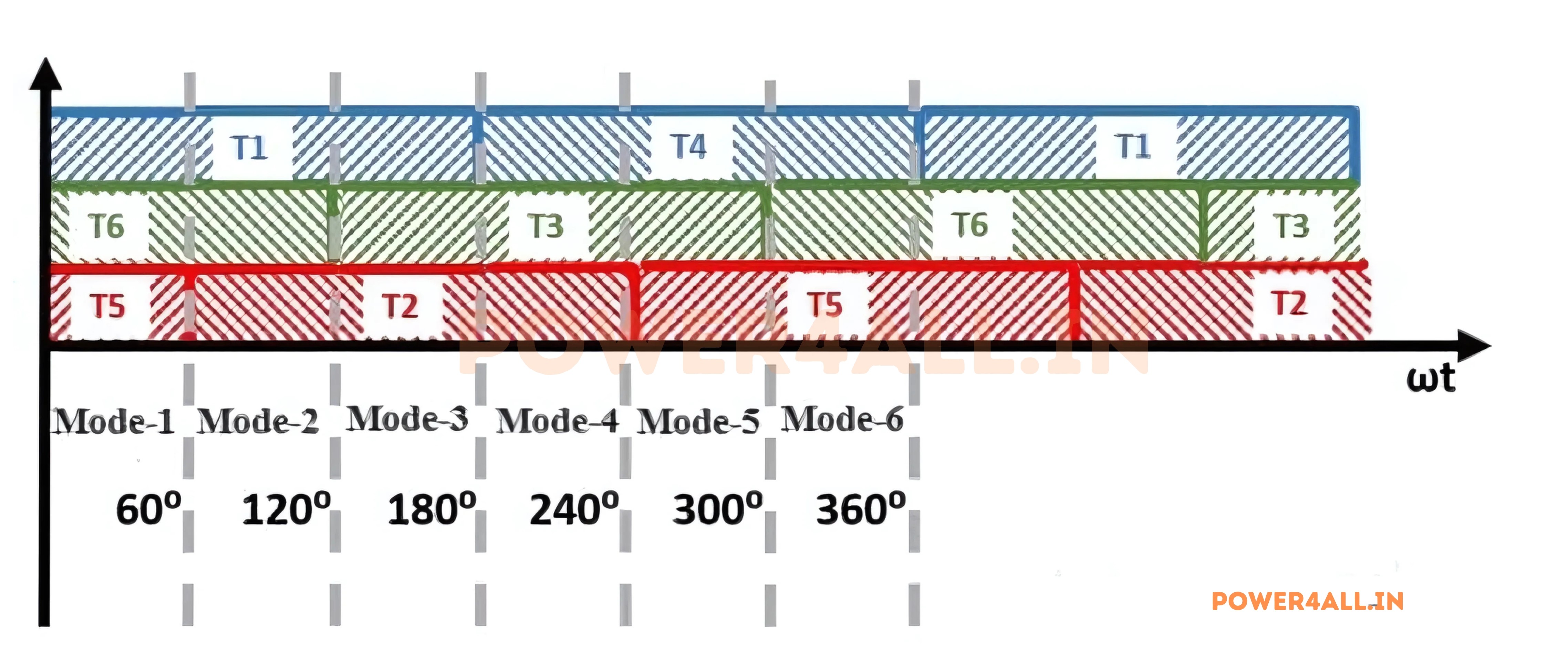
Mode 1: 0° to 60° Operation
In Mode 1, the operating range spans from 0° to 60°. During this interval, thyristors T1, T5, and T6 are switched on. As shown in the diagram below, current enters the load through phase a and phase c, and exits through phase b.
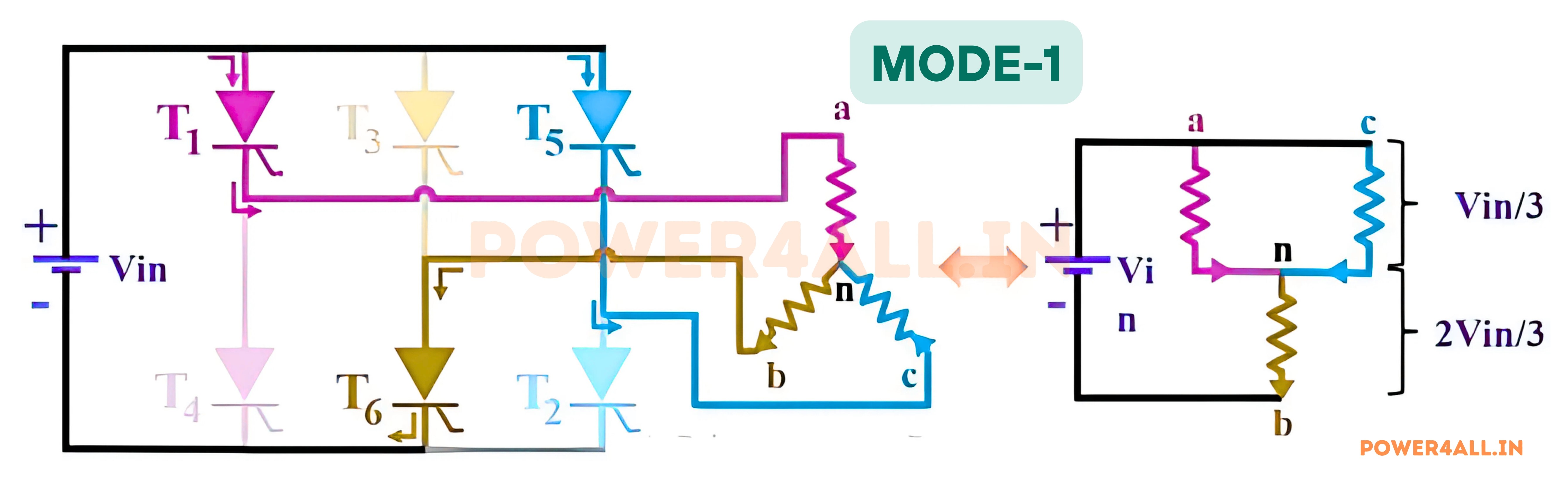
Phase-to-Neutral Voltages:
Van = Vin / 3Vbn = -2 × Vin / 3Vcn = Vin / 3
Phase-to-Phase Voltages:
Vab = Van - Vbn = VinVbc = Vbn - Vcn = -VinVca = Vcn - Van = 0
Mode 2: 60° to 120° Operation
Mode 2 covers the phase angle from 60° to 120°. In this mode, thyristors T1, T2, and T6 are turned on, as shown in the figure below.
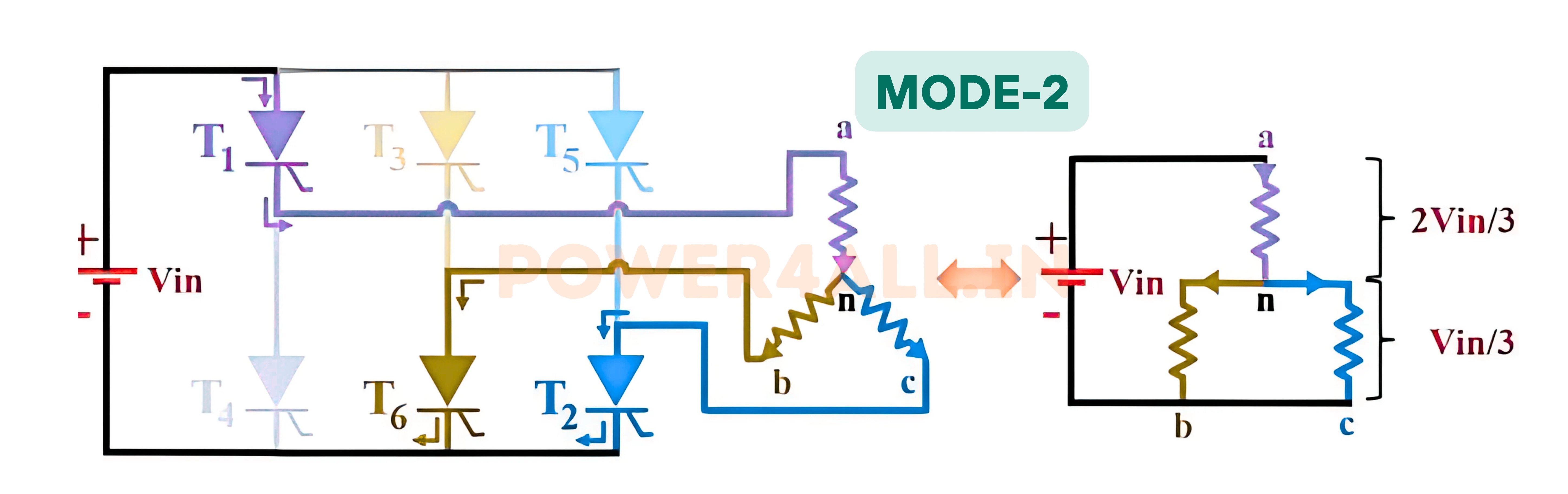
During this interval, current enters the load through phase a and exits through phases b and c. The equivalent circuit for this mode is displayed to the right of the illustration.
Phase-to-Neutral Voltages:
Van = 2 × Vin / 3Vbn = -Vin / 3Vcn = -Vin / 3
Phase-to-Phase Voltages:
Vab = Van - Vbn = VinVbc = Vbn - Vcn = 0Vca = Vcn - Van = -Vin
Mode 3: 120° to 180° Operation
Mode 3 covers the interval from 120° to 180°. During this period, thyristors T1, T2, and T3 are conducting. In this mode, current enters the load through phases a and b, and exits via phase c.
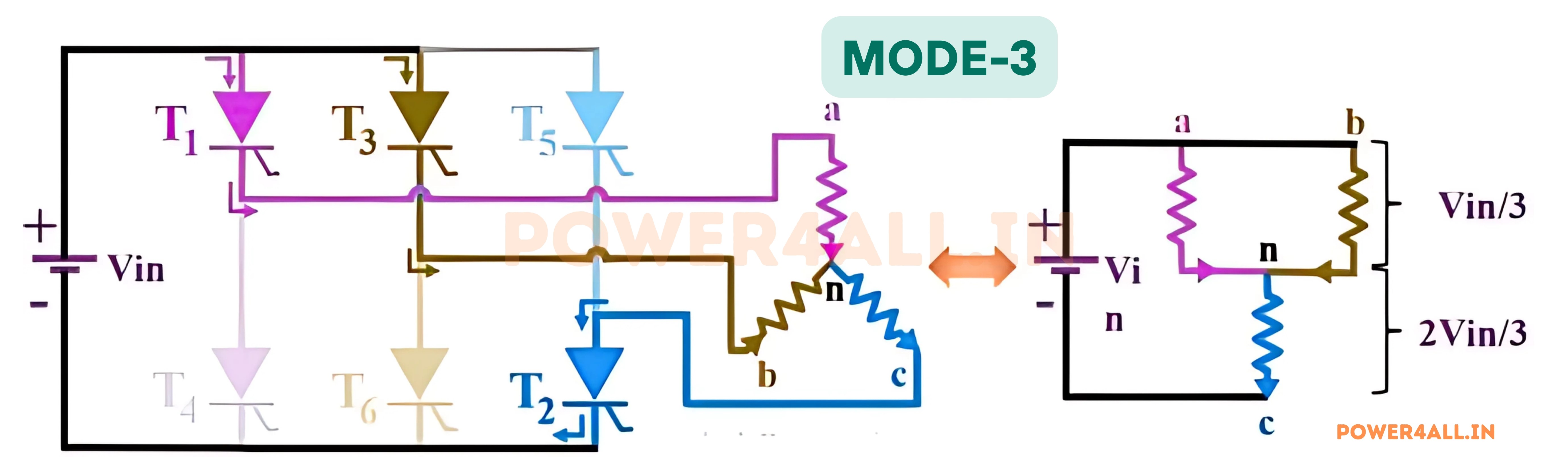
Phase-to-Neutral Voltages:
Van = Vin / 3Vbn = Vin / 3Vcn = -2 × Vin / 3
Phase-to-Phase Voltages:
Vab = Van - Vbn = 0Vbc = Vbn - Vcn = VinVca = Vcn - Van = -Vin
Mode 4: 180° to 240° Operation
Mode 4 spans from 180° to 240°. Here, thyristors T2, T3, and T4 are turned on. Current enters the load through phase b and leaves via phases a and c.
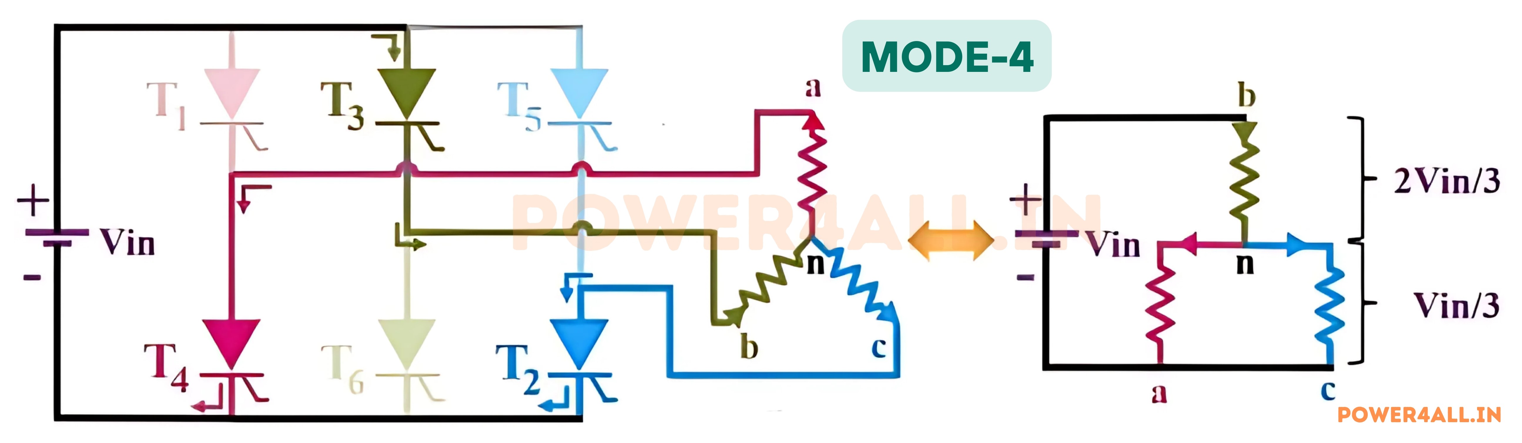
Phase-to-Neutral Voltages:
Van = -Vin / 3Vbn = 2 × Vin / 3Vcn = -Vin / 3
Phase-to-Phase Voltages:
Vab = Van - Vbn = -VinVbc = Vbn - Vcn = VinVca = Vcn - Van = 0
Mode 5: 240° to 300° Operation
Mode 5 covers 240° to 300°. During this mode, thyristors T3, T4, and T5 are conducting. The current enters through phase b and phase c, and leaves via phase a.
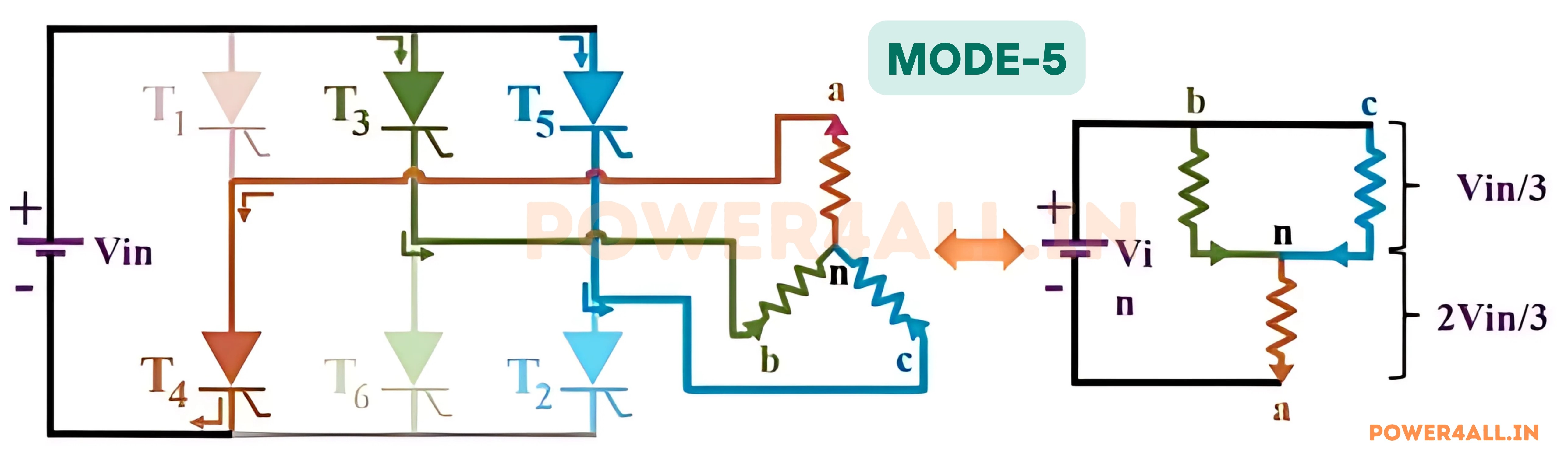
Phase-to-Neutral Voltages:
Van = -2 × Vin / 3Vbn = Vin / 3Vcn = Vin / 3
Phase-to-Phase Voltages:
Vab = Van - Vbn = -VinVbc = Vbn - Vcn = 0Vca = Vcn - Van = Vin
Mode 6: 300° to 360° Operation
Mode 6 corresponds to the 300° to 360° period. During this mode, thyristors T4, T5, and T6 are on. The current enters the load through phase c and leaves via phases a and b.
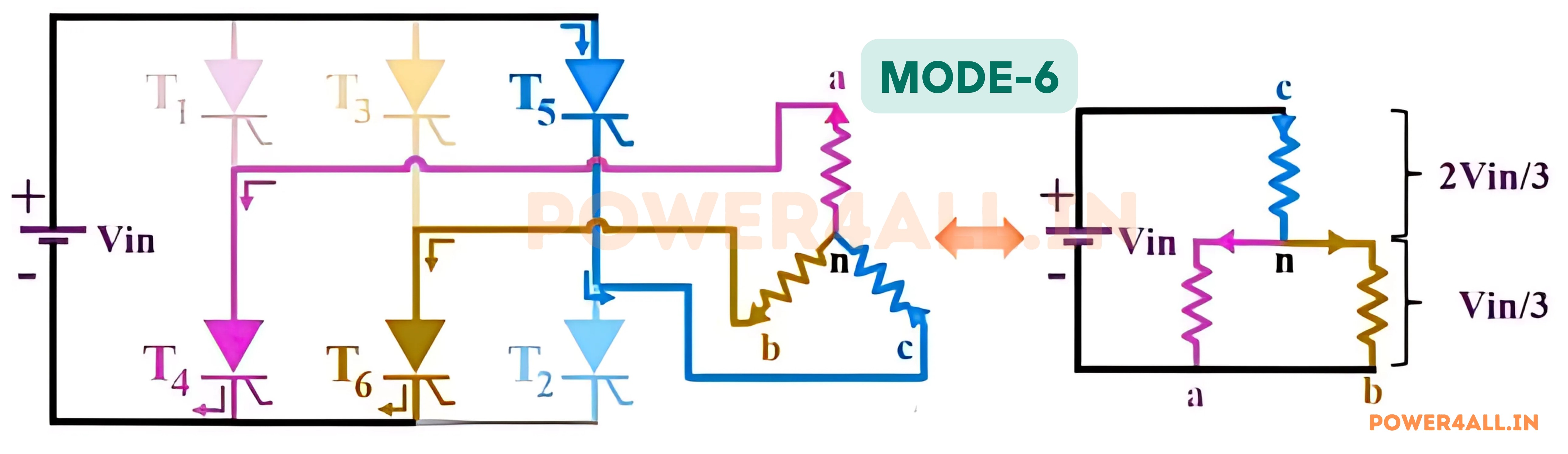
Phase-to-Neutral Voltages:
Van = -Vin / 3Vbn = -Vin / 3Vcn = 2 × Vin / 3
Phase-to-Phase Voltages:
Vab = Van - Vbn = 0Vbc = Vbn - Vcn = -VinVca = Vcn - Van = Vin
Output Voltage Waveform of 180° Mode Inverter:
The output voltage waveform of a three-phase inverter operating in 180-degree conduction mode is characterized by its continuous and balanced nature. The waveform consists of six distinct segments, each corresponding to the conduction of a specific thyristor pair. The output voltage remains constant during each segment, resulting in a smooth and stable three-phase AC output.
The figure below illustrates the phase voltages and line voltage waveform of a three-phase inverter in 180-degree conduction mode. The waveform is periodic, with each cycle lasting 360 degrees. The voltage levels during each segment are determined by the conduction states of the thyristors, ensuring that the output remains balanced across all three phases.

Advantages
- Provides a balanced three-phase AC output, ideal for industrial and motor loads.
- Delivers smoother voltage and current waveforms compared to single-phase inverters.
- Reduces harmonic distortion, resulting in better performance for sensitive equipment.
- Each thyristor conducts for 180 degrees, which helps distribute switching losses evenly.
- Capable of handling higher power and voltage levels, making it suitable for large-scale applications.
- Improved efficiency for three-phase loads due to continuous conduction mode.
Disadvantages
- Requires six switching devices and a complex triggering circuit for proper phase control.
- Greater circuit complexity compared to single-phase or 120-degree conduction inverters.
- More switching elements mean higher initial cost and increased maintenance.
- Still produces some harmonics, especially lower-order harmonics, which may need filtering in sensitive applications.
- Not as compact as single-phase solutions, requiring more space and careful layout.
- Careful synchronization is needed to avoid overlap and commutation issues between devices.
Applications
- Widely used in three-phase motor drives for industrial automation and robotics.
- Essential in variable frequency drives (VFDs) for speed control of AC motors.
- Used in renewable energy systems to connect solar or wind power to three-phase grids.
- Ideal for uninterruptible power supplies (UPS) that require three-phase output.
- Employed in induction heating and large-scale heating control systems.
- Common in high-power converters for electric vehicles and railway traction systems.