Complete Relay Mastery Guide
Master the fundamentals of relays - from basic concepts and types to advanced applications in switching circuits and automation systems
Complete Learning Path - Relay Fundamentals to Applications
Navigate through comprehensive coverage of relays from basic principles to advanced applications
What is a Relay?
A relay is an electrically operated switch that uses an electromagnet to mechanically operate switch contacts. Think of it as a remote-controlled switch - a small electrical signal can control a much larger electrical circuit, providing isolation and amplification. This makes relays essential for controlling high-power devices safely from low-power control circuits.
Small Signal → Controls → Large Load
The fundamental principle of relay operation
Why Relays are Essential
Relays bridge the gap between control circuits and power circuits, enabling safe and efficient control of high-power devices. They provide electrical isolation, signal amplification, and multiple switching capabilities that are crucial in modern electrical and electronic systems.
Electrical Isolation
Relays completely separate control circuits from load circuits, protecting sensitive electronics from high voltages and providing safety isolation.
Signal Amplification
A small control current (milliamps) can switch large load currents (amperes), providing significant current and power amplification.
Multiple Switching
Single relay can control multiple circuits simultaneously, making complex switching operations simple and synchronized.
Logic Implementation
Relays can implement logic functions (AND, OR, NOT) and create interlocking circuits for automation and safety systems.
Relay Symbol and Basic Components
Circuit Symbols
- Coil symbol: Rectangle or circle with terminals
- NO contacts: Normally Open (open when coil off)
- NC contacts: Normally Closed (closed when coil off)
- SPDT contacts: Single Pole Double Throw
- DPDT contacts: Double Pole Double Throw
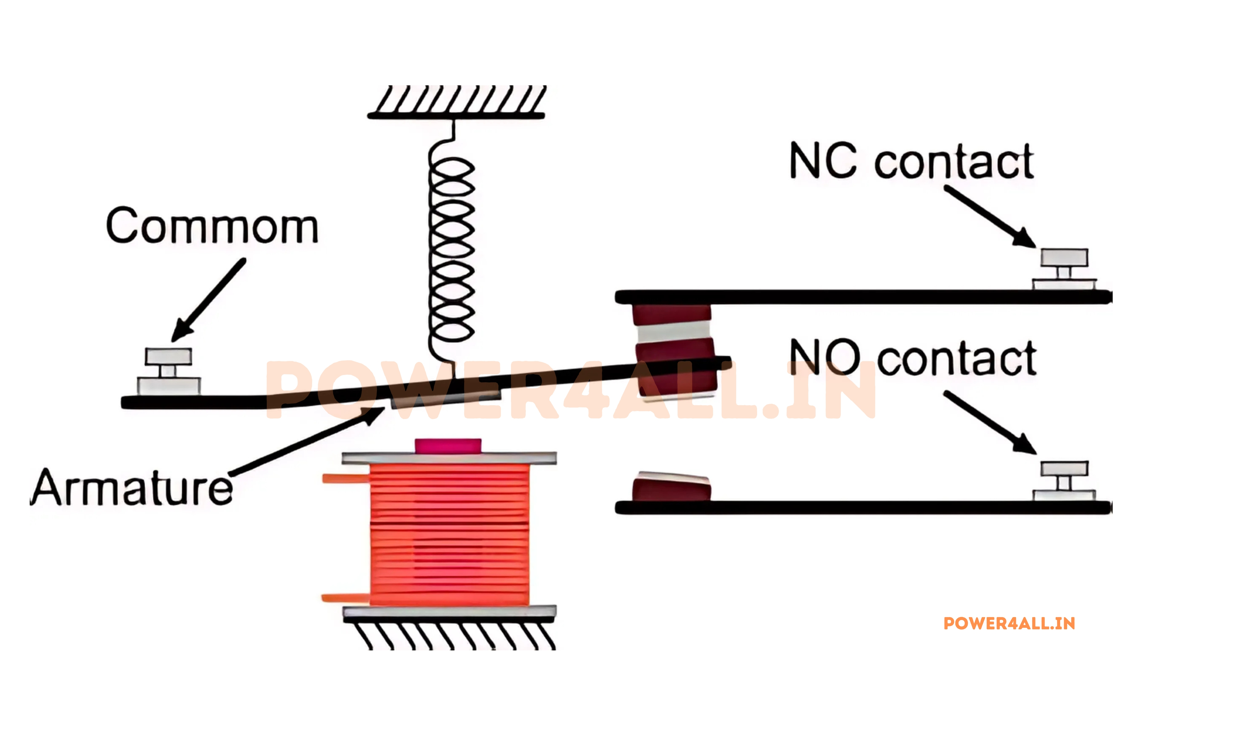
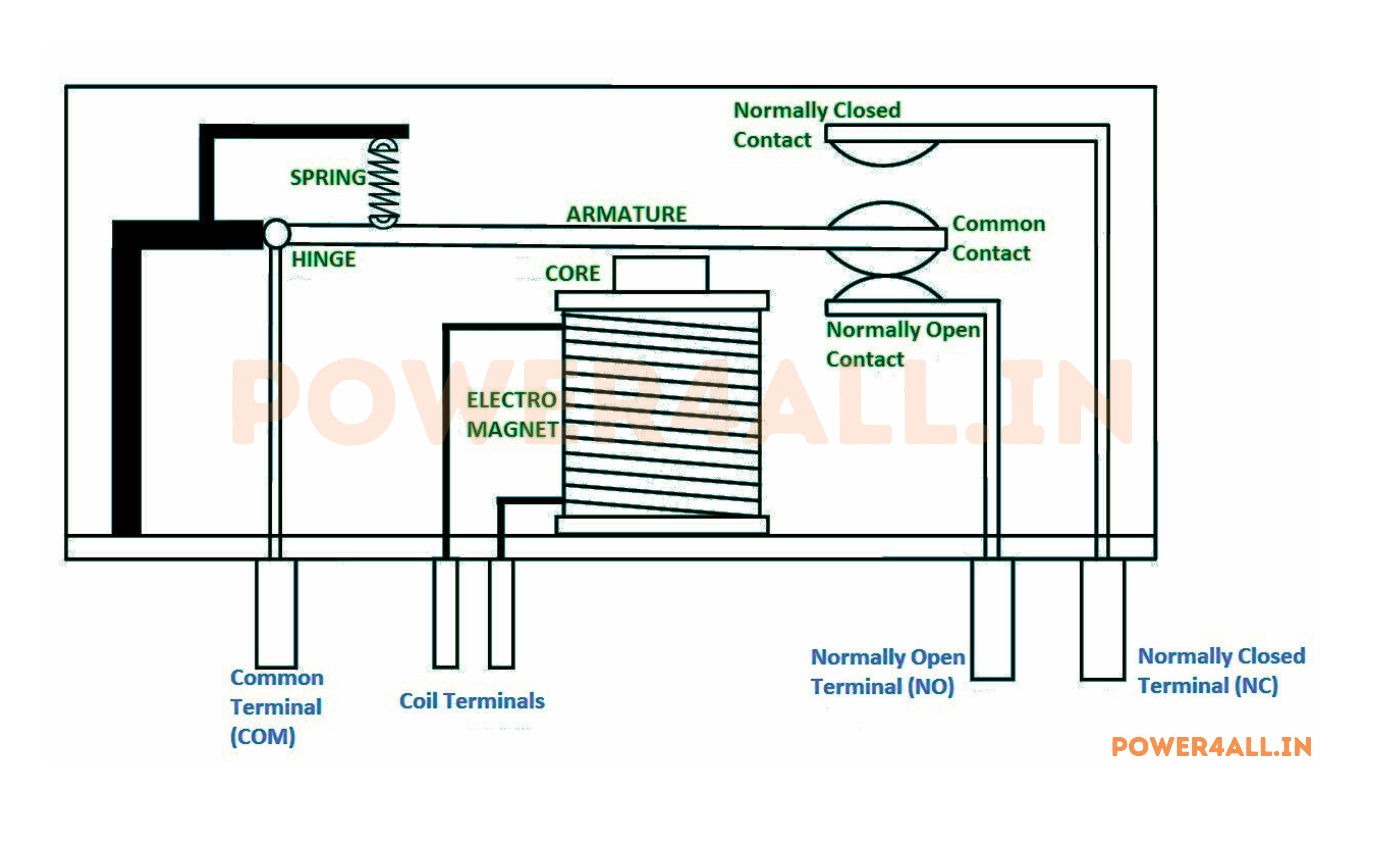
Basic Components
- Coil/Electromagnet: Creates magnetic field when energized
- Armature: Movable magnetic core that operates contacts
- Contacts: Switch elements that open/close circuits
- Spring: Returns armature to normal position
- Frame: Structural support and magnetic path
Everyday Relay Examples
- Car starter relay: Small switch signal starts high-power starter motor
- Air conditioning relay: Thermostat controls compressor motor
- Automotive horn relay: Horn button controls high-current horn
- Elevator control: Call buttons control elevator motor systems
- Industrial automation: PLC outputs control motors and valves
- Home automation: Smart switches control lighting and appliances
Did You Know?
The first relay was invented in 1835 by Joseph Henry for use in the telegraph system. Modern relays can switch currents from microamps to thousands of amperes, and can operate millions of times. They're still widely used despite the advent of solid-state switches because of their reliability, isolation, and ability to handle high currents!
Relay Fundamentals: How They Work
Understanding how relays operate involves exploring electromagnetic principles, mechanical switching action, and the relationship between control circuits and switched circuits. This knowledge is essential for proper relay selection, connection, and troubleshooting.
Electromagnetic Operating Principle
How Electromagnetic Force Creates Mechanical Motion
Relays work on the principle of electromagnetic induction. When current flows through the relay coil, it creates a magnetic field that attracts a movable armature, which in turn operates the switch contacts.
Step-by-Step Operation
| Component | Function | Material | Critical Properties |
|---|---|---|---|
| Coil | Generate magnetic field | Copper wire, insulation | Resistance, voltage rating |
| Core | Concentrate magnetic flux | Soft iron, laminated steel | Permeability, saturation |
| Armature | Convert magnetic force to motion | Magnetic steel | Mass, magnetic properties |
| Contacts | Switch electrical circuits | Silver, gold, tungsten | Conductivity, arc resistance |
| Spring | Return armature to normal position | Spring steel | Force, fatigue resistance |
F = B² × A / (2μ₀)
Magnetic force equation (B = flux density, A = area)
Types of Relays: Complete Classification
Relays come in numerous types, each designed for specific applications, operating conditions, and performance requirements. Understanding the various types helps in selecting the right relay for your particular application, whether it's general purpose switching, high-speed operation, or specialized control functions.
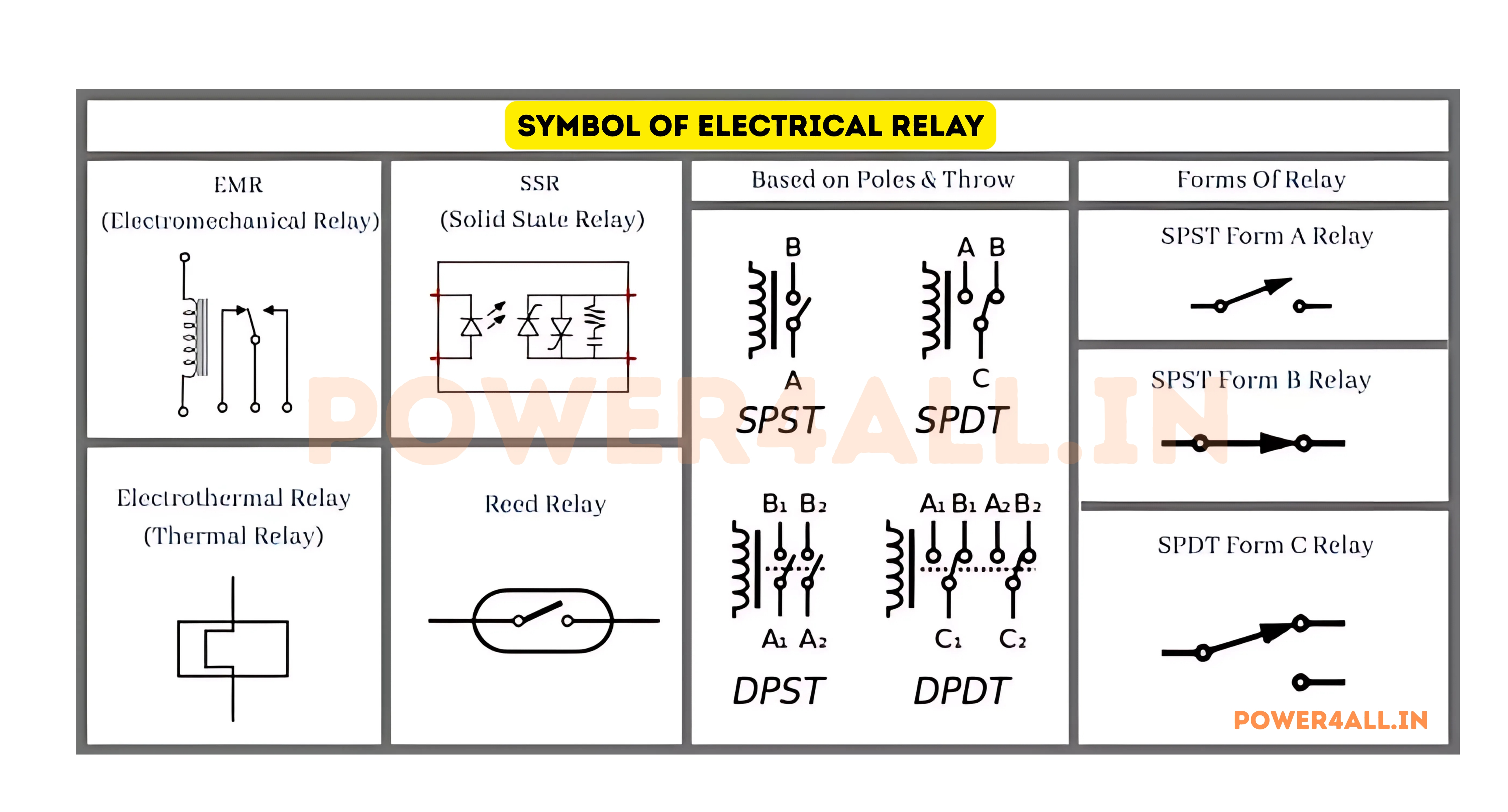
Electromagnetic Relays
SPST (Single Pole Single Throw)
Simple on/off switching
Configuration Options
- SPST-NO: Normally Open (Form A)
- SPST-NC: Normally Closed (Form B)
- Applications: Simple load control
- Contact rating: Single current rating
SPST Applications
- Motor start/stop control
- Lighting control systems
- Alarm circuit switching
- Power supply switching
SPDT (Single Pole Double Throw)
Three-terminal switching (Form C)
Terminal Designations
- Common (C): Always connected terminal
- Normally Open (NO): Connected when energized
- Normally Closed (NC): Connected when de-energized
- Function: Choose between two circuits
SPDT Applications
- Automatic/manual control switching
- Two-speed motor control
- Circuit changeover systems
- Backup power switching
DPDT (Double Pole Double Throw)
Dual circuit switching
Capabilities
- Two independent SPDT: Synchronized switching
- Isolated circuits: Two separate load circuits
- Reversing applications: Motor direction control
- Complex logic: Multiple circuit interactions
DPDT Applications
- Motor reversing circuits
- Phase switching systems
- Dual voltage switching
- Interlock safety circuits
Specialized Relay Types
High-Performance and Application-Specific Relays
Reed Relays
Reed Relay Advantages
Hermetically sealed contacts in glass envelope
Key Features
- Fast switching: <1ms operation time
- Long life: 10⁸ to 10⁹ operations
- Hermetic sealing: No contamination
- Low power: Minimal coil current
- High sensitivity: Low operate power
Reed Relay Applications
- Automatic test equipment
- Telecommunications switching
- Medical equipment
- High-frequency RF switching
- Precision instrumentation
Solid State Relays (SSR)
Electronic switching without moving parts
SSR Technologies
- TRIAC output: AC load switching
- MOSFET output: DC load switching
- SCR output: High power AC switching
- Optocoupler isolation: 2.5kV+ isolation
- Zero-crossing switching: Reduced EMI
SSR Applications
- Heating element control
- Motor speed control
- Lighting dimmers
- Process control systems
- High-speed switching
Safety and Control Relays
| Relay Type | Primary Function | Key Features | Applications |
|---|---|---|---|
| Safety Relays | Emergency stop and safety circuits | Forced-guided contacts, redundancy | Machine safety, emergency stops |
| Monitoring Relays | Monitor electrical parameters | Adjustable setpoints, LED indicators | Voltage, current, frequency monitoring |
| Interface Relays | Signal isolation and amplification | Slim design, LED indicators | PLC output amplification |
| Overload Relays | Motor protection | Thermal or electronic protection | Motor overload protection |
Relay Selection by Application
Residential Applications
Typical choice: General purpose 12V or 24V relays, 10-15A rating for HVAC, lighting, and appliance control.
Commercial Buildings
Typical choice: Power relays 30A+, time delay relays for sequencing, monitoring relays for system protection.
Industrial Automation
Typical choice: Interface relays for PLC outputs, safety relays for emergency stops, power relays for motors.
Automotive Systems
Typical choice: 12V automotive relays, sealed construction, vibration-resistant, high temperature rating.
Relay Specifications & Ratings
Understanding relay specifications is crucial for proper selection and application. Relay ratings define the limits of safe operation and ensure reliable performance in your specific application. This section covers all the key parameters you need to know for successful relay implementation.
Coil Specifications
Coil Voltage and Current
The coil specifications determine how the relay is controlled. Coil voltage must match your control circuit for proper operation and reliability.
P_coil = V_coil × I_coil
Coil power consumption
Coil Rating Example
12V DC relay with 180Ω coil resistance:
- Operate voltage: 12V nominal
- Coil current: 12V ÷ 180Ω = 67mA
- Coil power: 12V × 0.067A = 0.8W
- Pick-up voltage: ~9V (75% of nominal)
- Drop-out voltage: ~1.2V (10% of nominal)
Contact Ratings and Specifications
| Specification | Definition | Typical Values | Critical for |
|---|---|---|---|
| Contact Current | Maximum continuous current through contacts | 1A - 50A | Load current requirements |
| Contact Voltage | Maximum voltage across open contacts | 24V - 600V | Load voltage requirements |
| Breaking Capacity | Maximum current/voltage that can be interrupted | Varies by load type | Switching inductive/capacitive loads |
| Making Capacity | Maximum inrush current when closing | 5-10× steady current | Motor starting, lamp loads |
| Contact Resistance | Resistance when contacts are closed | 10mΩ - 100mΩ | Low voltage/current applications |
| Insulation Resistance | Resistance between isolated circuits | >100MΩ | Safety and signal isolation |
| Dielectric Strength | Voltage withstand between isolated circuits | 1kV - 6kV | Safety isolation requirements |
| Mechanical Life | Operations without electrical load | 10⁶ - 10⁸ operations | Long-term reliability |
| Electrical Life | Operations with rated electrical load | 10⁵ - 10⁶ operations | Application lifetime |
Load Type Considerations
How Different Loads Affect Relay Performance
Resistive Loads
Resistive loads (heating elements, incandescent lamps) are the easiest for relays to switch because current and voltage are in phase with no energy storage.
Resistive Load Characteristics
- No inrush current: Current equals V/R immediately
- No stored energy: Easy arc extinction
- Linear relationship: Ohm's law applies
- Examples: Heaters, resistive lamps, heating elements
- Relay advantage: Longest contact life
Inductive Load Challenges
- High inrush current: 5-8× normal current
- Back EMF: High voltage when switched off
- Sustained arcs: Difficult to extinguish
- Examples: Motors, solenoids, transformers
- Solutions: Arc suppression, higher ratings
Derating Factors for Different Loads
| Load Type | Derating Factor | Reason | Mitigation |
|---|---|---|---|
| Resistive (heaters) | 1.0× (full rating) | Ideal switching conditions | None needed |
| Incandescent lamps | 0.3-0.5× rating | High inrush current (10-15×) | Soft-start circuits |
| Fluorescent lamps | 0.2-0.3× rating | High inrush + ballast effects | Electronic ballasts |
| AC motors | 0.3-0.6× rating | High starting current | Soft starters, contactors |
| DC motors | 0.1-0.3× rating | Severe arcing on break | Arc suppression circuits |
| Capacitive | 0.2-0.4× rating | High charging current | Pre-charging circuits |
Load Derating Example
Switching a 5HP motor (24A full load current):
- Motor starting current: 6 × 24A = 144A (typical)
- Required relay rating: 24A ÷ 0.5 = 48A minimum
- Recommended selection: 60A relay for reliability
- Alternative: Use motor contactor instead of general relay
Environmental Specifications
Temperature Range
Operating: -40°C to +85°C typical. Storage: -55°C to +100°C. Coil resistance changes ~0.4%/°C for copper wire.
Humidity & Sealing
Standard: 85% RH max. Sealed: Washable, dust-tight. Hermetic: Welded seals for harsh environments.
Shock & Vibration
Shock: 50-100G typical. Vibration: 10-55Hz, 1.5mm displacement. Important for automotive and aerospace.
Safety Standards
UL: Recognized components. IEC: International standards. Safety: Creepage, clearance distances specified.
Relay Control Circuits
Control circuits determine when and how relays operate. From simple manual switches to complex automated systems, understanding control circuits is essential for implementing relay-based automation and control systems. This section covers various control methods and their applications.
Manual Control Methods
Switch Control
Direct manual control of relay operation
Switch Types
- Toggle switches: Maintained position control
- Pushbutton switches: Momentary or maintained
- Selector switches: Multiple position selection
- Key switches: Security-controlled operation
- Emergency stops: Immediate shutdown capability
Switch Control Applications
- Manual motor start/stop stations
- Lighting control panels
- Emergency shutdown systems
- Equipment selection switches
- Maintenance mode selection
Potentiometer Control
Variable voltage control for relay operation
Control Methods
- Voltage divider: Varies relay coil voltage
- Threshold setting: Adjustable trigger points
- Sensitivity control: Fine-tune operation levels
- Timer adjustment: Variable delay settings
Potentiometer Applications
- Temperature control setpoints
- Speed control systems
- Light level sensors
- Pressure switch adjustments
- Timer delay settings
Joystick Control
Multi-directional control for complex operations
Joystick Features
- Multi-axis control: X and Y direction sensing
- Multiple contacts: Different relays for each direction
- Proportional control: Analog output options
- Center return: Spring-loaded neutral position
Joystick Applications
- Crane and hoist control
- Robotic arm positioning
- Camera pan/tilt systems
- Vehicle steering controls
- Antenna positioning
Automatic Control Systems
Sensor-Based and Electronic Control Methods
Sensor Control Circuits
| Sensor Type | Control Method | Relay Application | Typical Use |
|---|---|---|---|
| Temperature Sensors | Thermostat, RTD, Thermocouple | Heating/cooling control | HVAC systems, industrial ovens |
| Pressure Switches | Mechanical or electronic | Pump/compressor control | Water systems, air compressors |
| Level Sensors | Float switches, ultrasonic | Pump/valve control | Tank filling, sump pumps |
| Proximity Sensors | Inductive, capacitive, optical | Position-based switching | Conveyor systems, safety gates |
| Motion Detectors | PIR, microwave, ultrasonic | Security/lighting control | Security systems, automatic lighting |
| Light Sensors | Photocells, photoresistors | Day/night switching | Street lighting, solar trackers |
Timer-Based Control
Time Delay Circuits
Controlling relay operation timing
Timer Types
- On-delay: Delay before relay energizes
- Off-delay: Delay before relay de-energizes
- Interval timer: Fixed duration operation
- Recycling timer: Continuous on/off cycling
Timer Applications
- Motor soft-start delays
- Pump alternation systems
- Stairway lighting timers
- Industrial process timing
Programmable Timers
Complex timing schedules and patterns
Advanced Features
- Multiple schedules: Different daily/weekly patterns
- Holiday programming: Exception handling
- Astronomical timing: Sunrise/sunset based
- Random variation: Security applications
Programmable Timer Uses
- Building lighting control
- Irrigation scheduling
- Security system automation
- Energy management systems
Electronic Control Interfaces
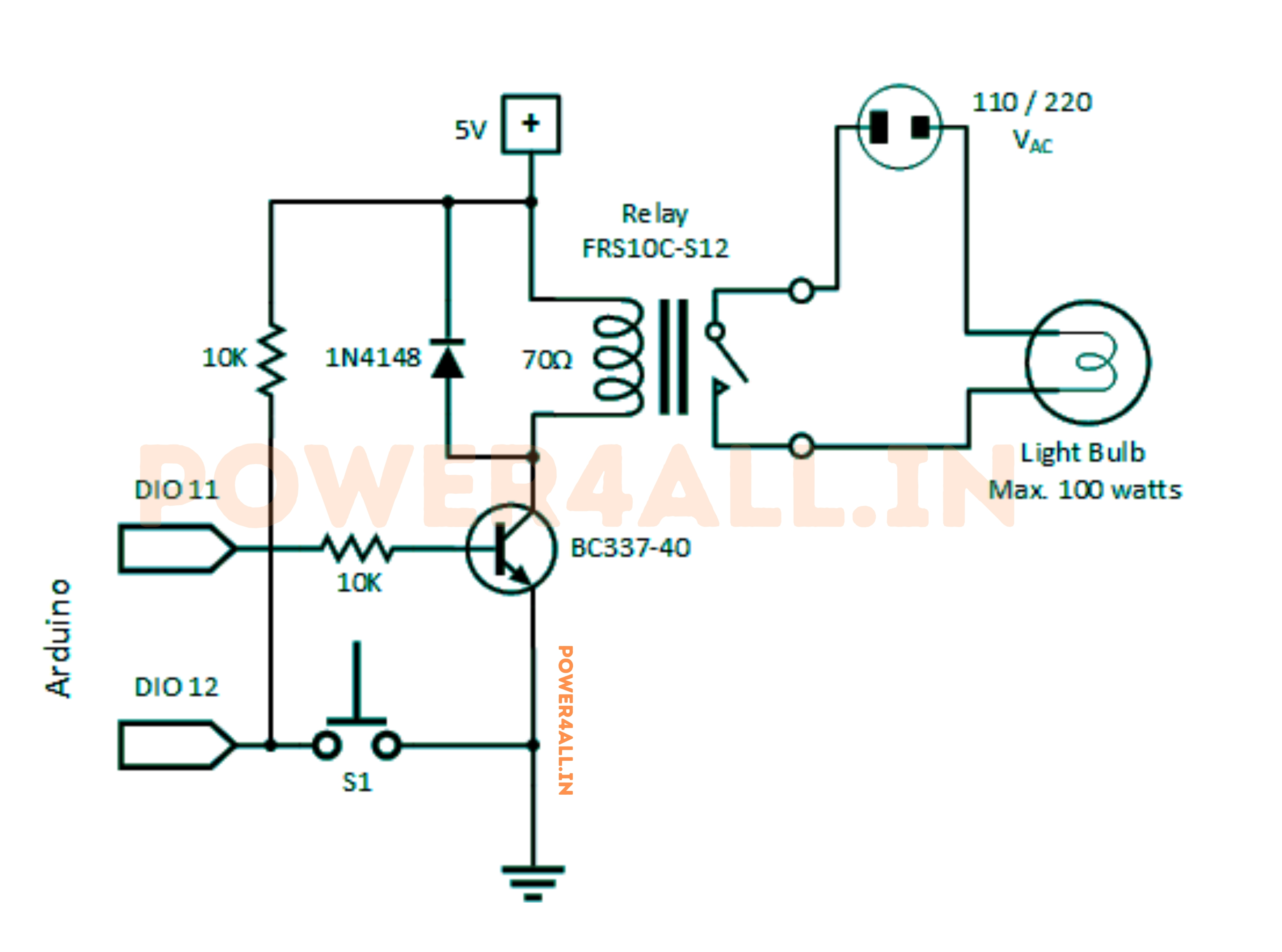
Microcontroller Control
Digital control using Arduino, PIC, or similar
Interface Methods
- Direct GPIO: Microcontroller pin to relay coil
- Transistor driver: Amplify low-current outputs
- Relay modules: Integrated driver circuits
- Optocoupler isolation: Protect microcontroller
Microcontroller Applications
- Home automation systems
- IoT control devices
- Industrial process control
- Agricultural automation
- Security system controllers
PLC Control
Programmable Logic Controller interfaces
PLC Output Types
- Transistor outputs: Direct relay coil drive (low voltage)
- Relay outputs: Built-in relays in PLC modules
- Triac outputs: AC load switching capability
- Interface relays: Amplify low-power PLC outputs
PLC Interface Applications
- Factory automation systems
- Conveyor control systems
- HVAC building control
- Water treatment plants
- Manufacturing process control
Practical Applications: Relays in Real World
Relays are ubiquitous in modern technology, from simple household appliances to complex industrial systems. Understanding their practical applications helps appreciate their importance and guides proper selection for specific uses.
Automotive Applications
Engine Management
Critical engine and safety systems
Essential Automotive Relays
- Starter relay: Controls high-current starter motor (200-400A)
- Fuel pump relay: Powers electric fuel pump system
- Horn relay: Amplifies horn button signal to horn load
- Headlight relay: Reduces load on headlight switch
- A/C clutch relay: Engages air conditioning compressor
- Cooling fan relay: Controls radiator cooling fans
Starter Relay Operation
- Control circuit: 12V, 150mA from ignition switch
- Load circuit: 12V, 300A to starter motor
- Isolation benefit: Small switch controls massive current
- Safety feature: Prevents accidental starter engagement
Electrical Systems
Power distribution and control
Power Management
- Main power relay: Master control for electrical systems
- ECU power relay: Controls engine control unit power
- Wiper relay: Intermittent wiper timing control
- Turn signal relay: Flashing indicator control
- Hazard relay: Emergency flasher system
Modern Vehicle Relay Count
- Basic car: 15-25 relays
- Luxury car: 40-60 relays
- Electric vehicle: 30-50 relays
- Commercial truck: 50-80 relays
Safety and Security
Critical safety system control
Safety Applications
- ABS relay: Anti-lock braking system pump control
- Airbag system relay: Safety restraint system power
- Central locking relay: Door lock actuator control
- Alarm system relay: Security system components
- Emergency flasher: Hazard warning system
Safety Critical
Automotive safety relays must meet strict reliability standards and operate in harsh conditions (-40°C to +125°C, vibration, moisture).
Industrial and Commercial Applications
Heavy-Duty and Precision Industrial Systems
Motor Control Systems
| Application | Relay Type | Control Voltage | Load Current | Special Requirements |
|---|---|---|---|---|
| Conveyor motor starter | Power contactor | 24V DC | 50-100A | Overload protection, emergency stop |
| Pump control | DPDT power relay | 120V AC | 30A | Level sensor input, alternation |
| Crane hoist | Safety relay | 24V DC | 25A | Forced-guided contacts, redundancy |
| HVAC damper | General purpose | 24V AC | 10A | Position feedback, modulating control |
Process Control Applications
Water Treatment
Control pumps, valves, and chemical dosing systems. Relays provide reliable switching for critical water quality processes.
Heating Systems
Industrial furnaces, boilers, and heating elements. High-power relays handle heating loads up to hundreds of kilowatts.
Ventilation Control
Fans, blowers, and dampers in HVAC systems. Coordinated relay operation maintains air quality and temperature.
Manufacturing
Assembly line control, robotic systems, and quality control. Precise timing and sequencing of operations.
Home and Building Applications
Residential Systems
Comfort and convenience automation
Common Home Applications
- Thermostat control: HVAC system switching (heat/cool)
- Garage door opener: Motor control and safety systems
- Pool equipment: Pump, heater, and lighting control
- Sprinkler systems: Zone valve control and scheduling
- Security systems: Alarm sirens and door locks
- Doorbell systems: Low voltage control of chimes
Smart Home Integration
- WiFi-controlled relay modules
- Voice assistant integration
- Smartphone app control
- Energy monitoring capabilities
- Schedule and timer functions
Commercial Buildings
Large-scale building automation
Building Management Systems
- Lighting control: Zone-based lighting automation
- HVAC systems: Central air handling unit control
- Fire safety: Smoke dampers and emergency systems
- Elevator systems: Motor and safety circuit control
- Access control: Electronic door locks and barriers
Energy Management
- Load shedding during peak demand
- Automatic equipment scheduling
- Demand response systems
- Power quality monitoring
- Emergency backup power switching
Power Distribution
Electrical panel and distribution control
Electrical Panel Applications
- Load switching: Remote control of circuit breakers
- Transfer switches: Automatic generator backup
- Power monitoring: Current and voltage sensing
- Load management: Priority-based load control
- Safety systems: Arc fault and ground fault protection
Backup Power Systems
- Automatic transfer switch (ATS) operation
- Generator start/stop control
- Load bank testing systems
- Battery backup switching
- Power quality monitoring
Relay Selection Guide: Choosing the Right Relay
Selecting the correct relay involves evaluating multiple parameters including coil voltage, contact ratings, environmental conditions, and application requirements. This comprehensive guide walks through the selection process step by step.
Selection Criteria Overview
Primary Selection Parameters
Successful relay selection requires systematic evaluation of electrical, mechanical, and environmental factors in order of importance.
Selection Priority by Application
- Automotive: Environmental rating > Contact rating > Size > Cost
- Industrial: Contact rating > Reliability > Environmental > Cost
- Consumer: Cost > Size > Contact rating > Performance
- Medical: Reliability > Contact rating > Environmental > Cost
- Aerospace: Reliability > Environmental > Weight > Performance
Load Analysis and Contact Selection
| Load Type | Characteristics | Relay Requirements | Derating Factor | Special Considerations |
|---|---|---|---|---|
| Resistive | Steady current, no inrush | Standard contact rating | 1.0× (full rating) | Simplest switching, longest life |
| Incandescent Lamps | 10-15× inrush current | High making capacity | 0.3× rating | Use tungsten-rated contacts |
| Fluorescent Lamps | High inrush + ballast | Arc suppression | 0.2× rating | Consider electronic ballasts |
| AC Motors | 6-8× starting current | Motor-rated contacts | 0.4× rating | Use motor contactors for >5HP |
| DC Motors | High starting current + arcing | DC-rated contacts | 0.1× rating | Requires arc suppression |
| Solenoids/Relays | Inductive load, back EMF | Inductive load rating | 0.5× rating | Use flyback diodes |
| Capacitive | High charging current | High making capacity | 0.3× rating | Pre-charging circuits help |
Environmental and Mechanical Considerations
Matching Relay to Operating Environment
Temperature Considerations
Low Temperature
Effects: Increased coil resistance, slower operation, contact sticking
Solutions: Cold-rated relays, heaters, insulation
High Temperature
Effects: Reduced contact rating, coil resistance changes, material degradation
Solutions: High-temperature materials, derating, cooling
Temperature Cycling
Effects: Thermal stress, solder joint fatigue, seal degradation
Solutions: Flexible leads, quality sealing, stress relief
Rate of Change
Effects: Thermal shock, expansion mismatch, cracking
Solutions: Gradual temperature changes, thermal mass
Contamination and Sealing
| Environment | Contamination Type | Sealing Required | Relay Type |
|---|---|---|---|
| Clean indoor | Dust, minor humidity | Open frame acceptable | Standard industrial |
| Dusty environment | Particulate matter | Dust cover or sealed | Enclosed case |
| High humidity | Moisture, condensation | Sealed enclosure | Hermetically sealed |
| Chemical exposure | Corrosive vapors | Hermetic seal required | Special alloy contacts |
| Washdown areas | Direct water spray | IP67 or better | Waterproof housing |
| Explosive atmosphere | Flammable gases | Explosion-proof | Intrinsically safe |
Sealing Level Selection
- Open frame: Cleanroom, controlled environment
- Plastic cover: Light dust protection, cost-sensitive
- Sealed case: Industrial environment, moderate contamination
- Hermetic seal: Harsh chemicals, extreme environments
- Explosion-proof: Hazardous locations, safety-critical
Performance and Reliability Factors
Operating Life Requirements
Expected service life and reliability
Life Cycle Specifications
- Mechanical life: Operations without electrical load
- Electrical life: Operations under rated electrical load
- Contact life: Specific to load type and conditions
- Coil life: Continuous energization capability
Life Expectancy by Application
- Automotive (20 years): 100,000-500,000 operations
- Appliance (10 years): 50,000-100,000 operations
- Industrial (25 years): 1,000,000+ operations
- Telecommunications: 10,000,000+ operations
Speed and Timing
Operating speed requirements
Timing Specifications
- Operate time: 3-50ms typical for electromagnetic
- Release time: 1-20ms typical
- Contact bounce: 0.5-5ms duration
- Maximum switching rate: Operations per minute
Speed Requirements by Application
- Power switching: Speed not critical (>50ms acceptable)
- Motor control: Moderate speed (10-20ms typical)
- Communications: Fast switching (<5ms required)
- Test equipment: Very fast (<1ms needed)
Safety and Standards
Regulatory and safety requirements
Common Standards
- UL (Underwriters Laboratories): North American safety
- IEC (International Electrotechnical Commission): International standards
- VDE (German standards): European electrical safety
- CSA (Canadian Standards Association): Canadian requirements
- CE marking: European Conformity
Application-Specific Standards
- Automotive: AEC-Q200 qualification
- Railway: EN 50121 electromagnetic compatibility
- Marine: IEC 60945 maritime equipment
- Medical: IEC 60601 medical electrical equipment
- Aerospace: DO-160 environmental conditions
Testing & Troubleshooting Relays
Proper testing and troubleshooting of relays requires understanding their failure modes, measurement techniques, and systematic diagnostic procedures. This knowledge is essential for maintaining reliable relay-based systems and quickly identifying problems.
Basic Relay Testing
Visual and Physical Inspection
Always start with visual inspection before electrical testing. Many relay problems are visible and can save time in diagnosis.
Visual Inspection Checklist
- Case integrity: No cracks or damage
- Terminal condition: Clean, tight connections
- Contact appearance: No visible burning or welding
- Coil condition: No signs of overheating
- Mounting: Secure and properly oriented
- Environmental: No moisture or contamination
Electrical Testing Procedures
Coil Testing
Verifying coil integrity and operation
Basic Coil Tests
- Resistance measurement: Check coil resistance with multimeter
- Insulation test: Measure resistance between coil and contacts
- Operation test: Apply rated voltage and verify clicking
- Current draw test: Measure coil current at rated voltage
Coil Resistance Test
12V DC relay coil (typical specifications):
- Expected resistance: 300-500Ω typical
- Open coil: Infinite resistance
- Shorted coil: Very low resistance (<10Ω)
- Partial short: Lower than expected resistance
- High resistance: Possible corrosion or damage
Contact Testing
Verifying contact operation and integrity
Contact Test Methods
- Continuity test: Check contact closure with multimeter
- Contact resistance: Measure resistance when closed
- Insulation test: Verify open contacts don't conduct
- Load test: Test with actual load current
Contact Performance Criteria
- Closed contact resistance: <100mΩ for power contacts
- Open contact insulation: >100MΩ minimum
- Operate voltage: 75-85% of nominal typically
- Release voltage: 5-20% of nominal typically
Timing Tests
Measuring relay operating speed and timing
Timing Measurements
- Operate time: Time from coil energize to contact closure
- Release time: Time from coil de-energize to contact opening
- Contact bounce: Duration of contact instability
- Overlap time: For changeover contacts
Timing Test Equipment
- Oscilloscope: Most accurate timing measurements
- Digital multimeter: Basic timing functions
- Relay tester: Specialized test equipment
- Function generator: For repetitive testing
Common Failure Modes and Diagnosis
Understanding How Relays Fail and Why
Coil Failures
| Failure Mode | Symptoms | Causes | Test Method | Prevention |
|---|---|---|---|---|
| Open coil | No operation, infinite resistance | Wire breakage, thermal stress | Resistance measurement | Proper voltage rating, surge protection |
| Shorted turns | Low resistance, overheating | Insulation breakdown, moisture | Resistance, current measurement | Proper sealing, environmental protection |
| Ground fault | Low insulation resistance | Moisture, contamination | Insulation resistance test | Sealed enclosures, proper mounting |
| High resistance | Weak operation, slow response | Corrosion, poor connections | Resistance comparison | Clean environment, quality terminals |
Contact Failures
| Failure Mode | Symptoms | Causes | Test Method | Prevention |
|---|---|---|---|---|
| Contact welding | Contacts stuck closed | Overcurrent, arcing | Continuity test when de-energized | Proper current rating, arc suppression |
| Contact pitting | High contact resistance | Arcing, material transfer | Contact resistance measurement | Appropriate contact material |
| Contact sticking | Intermittent operation | Contamination, corrosion | Multiple operate/release cycles | Sealed contacts, clean environment |
| Contact erosion | Increasing contact resistance | Normal wear, excessive switching | Visual inspection, resistance | Proper load derating |
Troubleshooting Process
- Gather information: Symptoms, operating conditions, history
- Visual inspection: Look for obvious damage or wear
- Basic electrical tests: Coil resistance, contact continuity
- Operational tests: Apply rated voltage, check operation
- Load tests: Test under actual operating conditions
- Environmental check: Verify operating conditions are within spec
Safety During Testing
- De-energize circuits before connecting test equipment
- Use proper PPE when working with high voltage systems
- Verify test equipment ratings match circuit voltages
- Use lockout/tagout procedures for industrial systems
- Be aware of stored energy in capacitive circuits
Advanced Relay Concepts
Beyond basic relay operation lies sophisticated applications involving protective relays, smart relays, digital communication, and specialized switching techniques. Understanding these advanced concepts opens possibilities for complex automation and protection systems.
Protective Relays
Overcurrent Protection
Sophisticated current monitoring and protection
Protection Functions
- Instantaneous overcurrent: Immediate trip for severe faults
- Time-delayed overcurrent: Inverse time characteristics
- Ground fault protection: Detect earth leakage currents
- Negative sequence: Detect unbalanced conditions
- Directional protection: Power flow direction sensing
Motor Protection Example
- Overload protection: I²t thermal model
- Locked rotor: High current detection
- Phase loss: Voltage/current unbalance
- Undervoltage: Minimum voltage monitoring
- Ground fault: Zero sequence current
Voltage and Frequency Protection
Power quality monitoring and protection
Monitoring Parameters
- Overvoltage protection: High voltage disconnect
- Undervoltage protection: Low voltage detection
- Frequency protection: Over/under frequency relays
- Rate of change: df/dt and dV/dt protection
- Voltage unbalance: Phase voltage monitoring
Grid Protection Applications
- Generator protection systems
- Transmission line protection
- Distribution feeder protection
- Microgrid interconnection
- Renewable energy integration
Time Coordination
Selective coordination of protection systems
Coordination Principles
- Time grading: Upstream delays longer than downstream
- Current grading: Different pickup settings
- Directional coordination: Flow direction consideration
- Zone protection: Primary and backup zones
Coordination Example
- Feeder protection: 0.1s operate time
- Substation protection: 0.4s operate time
- Transmission protection: 0.7s operate time
- Result: Closest protection operates first
Specialized Relay Applications
Automation and Control
Advanced control system integration
Modern Automation Features
- PID control loops: Integrated process control
- Logic functions: Boolean logic implementation
- Sequence control: Step-by-step process automation
- Data logging: Historical trend recording
- Alarm management: Intelligent alarm processing
Smart Building Integration
- HVAC optimization algorithms
- Energy management systems
- Occupancy-based control
- Demand response participation
- Predictive maintenance scheduling
IoT and Cloud Integration
Internet connectivity and cloud services
IoT Capabilities
- Remote monitoring: Real-time status and control
- Cloud analytics: Big data analysis and insights
- Mobile apps: Smartphone and tablet interfaces
- API integration: Third-party system connections
- Edge computing: Local intelligence and processing
Industry 4.0 Applications
- Predictive maintenance using AI
- Digital twin integration
- Machine learning optimization
- Blockchain for security
- Augmented reality maintenance
Safety Considerations: Working Safely with Relays
Relay circuits often involve high voltages and currents that can be dangerous to personnel and equipment. Understanding safety principles, proper procedures, and protective measures is essential for safe installation, maintenance, and operation of relay-based systems.
Electrical Safety Hazards
High Voltage Warning
Relay circuits often control high-voltage loads that can cause severe injury or death. Always assume circuits are energized until proven otherwise with proper test equipment. Use appropriate lockout/tagout procedures.
Shock and Electrocution
Primary electrical safety hazards
Voltage Hazard Levels
- Low voltage (≤50V): Generally safe but still requires caution
- Medium voltage (50-1000V): Dangerous, can cause severe injury
- High voltage (>1000V): Lethal, requires specialized procedures
- Control circuits: Often 24-120V, seemingly safe but hazardous
Common Relay Voltage Levels
- Automotive relays: 12V DC (generally safe)
- Industrial control: 24-120V (moderate hazard)
- Motor contactors: 240-480V (dangerous)
- Utility relays: kV levels (lethal)
Arc Flash and Burn Hazards
High-energy electrical faults and their dangers
Arc Flash Conditions
- High available fault current: >1000A potential
- Switching operations: Making and breaking under load
- Maintenance activities: Working on energized equipment
- Equipment failures: Insulation breakdown, loose connections
Arc Flash Energy Levels
- 1.2 cal/cm²: Second-degree burns
- 8 cal/cm²: 50% chance of fatality
- 40 cal/cm²: 99% chance of fatality
- Industrial systems: Can exceed 100 cal/cm²
Secondary Effects
Indirect hazards from electrical incidents
Secondary Hazards
- Falls: Electrical shock causing loss of balance
- Burns: Heated tools and components
- Hearing damage: Arc blast sound pressure
- Toxic gases: Burning insulation and materials
- Fire: Ignition of flammable materials
Muscle Control Effects
- 1-5 mA: Barely perceptible
- 5-10 mA: Painful shock
- 10-20 mA: Muscular control lost
- 50-100 mA: Ventricular fibrillation
- 100-200 mA: Certain death
Safety Procedures and Protocols
Systematic Approach to Safe Work Practices
Lockout/Tagout (LOTO) Procedures
Design Safety Considerations
Safety Relay Systems
Relays designed specifically for safety functions
Safety Relay Features
- Forced-guided contacts: Mechanical linkage prevents welding
- Redundant contacts: Multiple contacts in series
- Self-monitoring: Automatic contact verification
- Fail-safe operation: Safe state on any failure
- Manual reset: Requires human intervention to restart
Safety-Critical Applications
- Emergency stop systems
- Machine guarding interlocks
- Two-hand control systems
- Light curtain interfaces
- Pressure-sensitive mat controls
Circuit Design Safety
Safe circuit design principles
Safety Design Principles
- Fail-safe design: Failures result in safe conditions
- Redundancy: Multiple protection levels
- Diversity: Different protection methods
- Independence: Separate protection systems
- Testability: Ability to verify proper operation
Emergency Stop Circuit
- Hardwired: No software dependencies
- Series contacts: Any open contact stops system
- Positive opening: Mechanical contact separation
- Manual reset: Intentional restart required
- Monitoring: Continuous circuit verification
Standards and Codes
Regulatory requirements and industry standards
Key Safety Standards
- NFPA 70E: Electrical safety in the workplace
- IEEE 1584: Arc flash hazard calculation
- IEC 61508: Functional safety standard
- ISO 13849: Safety of machinery
- OSHA 1910: Occupational safety regulations
Compliance Requirements
- Safety integrity level (SIL) ratings
- Performance level (PL) classifications
- Arc flash boundary calculations
- Personal protective equipment selection
- Training and qualification requirements
Safety Culture
Safety is not just about following procedures - it requires a culture of continuous awareness, ongoing training, and personal responsibility. Never compromise safety for schedule or convenience.
Frequently Asked Questions About Relays
Here are the most common questions about relays, covering everything from basic concepts to practical applications. These answers help clarify common misconceptions and provide practical guidance for working with relays.
Basic Concept Questions
Q: What's the difference between a relay and a contactor?
A: While both are electromagnetic switches, they differ primarily in current handling capability and construction:
| Characteristic | Relay | Contactor |
|---|---|---|
| Current Rating | Typically <30A | 30A to 1000A+ |
| Construction | Compact, enclosed | Heavy-duty, often open |
| Arc Suppression | Basic or none | Advanced arc chutes |
| Applications | Control circuits, low power | Motor control, high power |
| Auxiliary Contacts | Often built-in | Add-on modules |
Q: When should I use a relay instead of a switch?
A: Relays offer several advantages over mechanical switches in many applications:
Use a relay when you need:
- Remote control: Switch loads from a distance
- Low-power control: Small signal controls large load
- Electrical isolation: Separate control and load circuits
- Multiple switching: One control signal switches multiple loads
- Automatic operation: Sensor or timer-based switching
- High switching speed: Faster than manual switches
- Harsh environments: Control circuit in safe location
Use a manual switch when you need:
- Simple operation: Direct user control
- No power required: Mechanical operation only
- Emergency operation: Guaranteed operation during power failure
- Cost sensitivity: Lower cost for simple applications
Q: Can I use a DC relay with AC voltage or vice versa?
A: Generally no, but it depends on whether you're talking about the coil or the contacts:
Coil Considerations:
- DC relay with AC: May work but will buzz loudly due to AC magnetic field variations. Not recommended.
- AC relay with DC: Will operate but may not release properly due to lack of zero-crossing. Could overheat.
- Universal relays: Some relays are designed to work with both AC and DC coil voltage.
Contact Considerations:
- AC contacts with DC: May work for low currents, but DC arcing is harder to extinguish.
- DC contacts with AC: Usually acceptable as AC is easier to interrupt.
- Voltage rating: DC and AC voltage ratings are often different for the same relay.
Safety Note
Always use relays specifically rated for your voltage type and level. Misapplication can lead to failure, fire, or safety hazards.
Selection and Application Questions
Q: How do I calculate the required relay contact rating?
A: Contact rating depends on load type and operating conditions. Here's the process:
Calculation Example
5HP motor at 240V, 3-phase:
- Full load current: 15A (from motor nameplate)
- Starting current: 6 × 15A = 90A typical
- Motor load derating: Use 40% of relay rating
- Required relay rating: 15A ÷ 0.4 = 37.5A
- Safety margin: 37.5A × 1.25 = 47A
- Selection: Choose 50A rated contactor
Q: How do I choose the right coil voltage?
A: Coil voltage should match your control circuit voltage and consider these factors:
Voltage Selection Criteria:
- Available control voltage: Must match what's available in your panel
- Voltage stability: Consider voltage variations (±10% typical)
- Safety considerations: Lower voltages are generally safer
- Power consumption: Higher voltages typically use less current
- Wire size: Lower voltages require larger control wires
| Coil Voltage | Typical Applications | Advantages | Disadvantages |
|---|---|---|---|
| 12V DC | Automotive, security | Very safe, battery compatible | High current, large wires |
| 24V DC/AC | Industrial control | Safe, widely available | Moderate current requirements |
| 120V AC | Commercial, residential | Standard voltage, low current | Higher shock hazard |
| 240V AC | Industrial equipment | Very low current, small wires | High shock hazard |
Troubleshooting Questions
Q: My relay clicks but the load doesn't turn on. What's wrong?
A: A clicking relay indicates the coil is working, so the problem is likely in the contact circuit:
Possible Causes:
- Welded contacts: Contacts stuck in open position
- Blown fuse: Check load circuit protection
- Loose connections: Verify all wire connections are tight
- Wrong contact selection: Using NC instead of NO contacts
- Insufficient contact rating: Contacts damaged by overcurrent
- Load circuit open: Break somewhere in load wiring
Diagnostic Steps:
- Verify load circuit voltage with relay energized
- Check continuity through relay contacts
- Test load independently to verify it works
- Inspect relay contacts for damage or welding
- Check all connections and fuses in load circuit
Q: How long should a relay last?
A: Relay life depends on many factors, but here are typical expectations:
Life Expectancy Factors:
- Load type: Resistive loads give longest life
- Current level: Higher currents reduce contact life
- Switching frequency: More operations = shorter life
- Environmental conditions: Temperature, humidity, contamination
- Quality level: Industrial vs consumer grade
| Application | Expected Operations | Typical Lifespan | Replacement Strategy |
|---|---|---|---|
| HVAC control | 100,000-500,000 | 10-20 years | Replace on failure |
| Motor starter | 500,000-1,000,000 | 15-25 years | Preventive maintenance |
| Automotive | 100,000-200,000 | Vehicle lifetime | Replace on failure |
| Process control | 1,000,000+ | 20+ years | Scheduled replacement |
Conclusion: Mastering Relay Technology
Congratulations! You've completed a comprehensive journey through the world of relays, from fundamental electromagnetic principles to advanced smart relay systems. This knowledge foundation will serve you well in designing, troubleshooting, and implementing relay-based control systems across many applications.
Key Takeaways
Fundamental Understanding
Relays are electromagnetic switches that provide isolation, amplification, and control. This simple concept enables complex automation across countless applications.
Proper Selection
Successful relay application requires careful consideration of coil voltage, contact ratings, load types, and environmental conditions for reliable operation.
Safety First
Relays often control high-power circuits. Always follow proper safety procedures, use appropriate PPE, and implement proper lockout/tagout practices.
Modern Evolution
From simple electromagnetic switches to smart, connected devices with AI capabilities, relays continue evolving to meet modern automation needs.
Congratulations!
You now have a comprehensive understanding of relay technology, from basic electromagnetic principles to advanced smart relay systems. Remember that mastery comes through continued learning and practical application. Use this knowledge responsibly and always prioritize safety in your designs and implementations.