Cycloconverter
Cycloconverter in Power Electronics: Types, Working, and Applications
Introduction
Cycloconverters represent power electronic devices engineered to directly convert electric power from one frequency to another without necessitating an intermediate DC link. They find application in specialized systems where precise control of output frequency and low harmonic distortion are paramount.
Not with standing their utility, challenges are presented, including the complexity of control strategies and the presence of harmonics in the output waveform, demanding meticulous design and control to attain peak performance.
Essentially constituting a one-stage frequency changer, a cycloconverter operates on the fundamental principle of disintegrating the input AC power into smaller segments, subsequently reconstructing them to generate the desired output frequency.
What is a Cycloconverter?
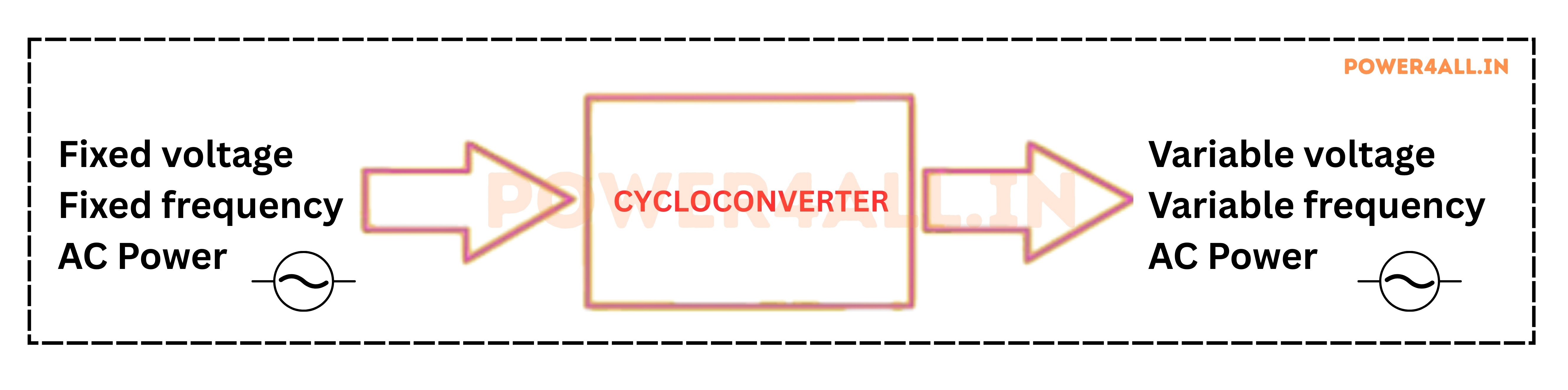
Definition of Cycloconverter: A cycloconverter, also known as an AC-to-AC converter or a frequency changer, is a solid-state device that transforms the AC power of one frequency into AC power of another adjustable frequency. The term "cycloconverter" originates from the Greek word "cyclo," signifying circle or periodicity. Essentially, a cycloconverter is an AC-to-AC converter capable of modifying the frequency of an input AC supply without the utilization of an intermediate DC link.
Block Diagram Of Cycloconverter
How Does a Cycloconverter Work?
Cycloconverters work by switching sections of the input AC waveform to the output, using power electronic switches such as thyristors. By carefully controlling the firing angles of these switches, the cycloconverter can synthesize an output AC waveform at a lower frequency than the input. This process involves two main modes:
- Rectification Mode: The positive half-cycles of the input are selected to create positive output voltage.
- Inversion Mode: The negative half-cycles are selected to create negative output voltage.
By alternating between these modes and adjusting the timing, the cycloconverter generates a stepped output waveform that mimics a lower-frequency AC supply. Modern cycloconverters use microcontroller-based firing circuits for precise control, and may employ advanced techniques like PWM (Pulse Width Modulation) to improve waveform quality and reduce harmonics.
Main Types of Cycloconverters
- Single-Phase to Single-Phase Cycloconverter: Converts single-phase AC at one frequency to single-phase AC at a lower frequency. Used for speed control of small single-phase motors.
- Three-Phase to Single-Phase Cycloconverter: Converts three-phase input to single-phase output. Less common, used in specialized power supplies.
- Single-Phase to Three-Phase Cycloconverter: Converts single-phase input to three-phase output. Useful where only single-phase supply is available but a three-phase load is needed.
- Three-Phase to Three-Phase Cycloconverter: Most widely used in industry. Converts three-phase AC at one frequency to three-phase AC at a lower frequency, ideal for large motor drives in steel mills, cement plants, and marine propulsion.
Cycloconverters are also classified by their operating mode:
- Circulating Current Type: Both positive and negative converters operate simultaneously, with circulating current between them.
- Blocking Mode Type: Only one converter operates at a time, blocking current in the other. Most commercial cycloconverters use this method due to higher efficiency and simpler control.
Cycloconverter Topologies
- Bridge-Type Cycloconverter: Uses two full-wave converters connected back-to-back. Only one operates at a time, depending on the polarity of the output.
- Midpoint-Type Cycloconverter: Uses center-tapped transformers and fewer switches. Simpler but less common in high-power applications.
The choice of topology depends on the application, required power level, and output waveform quality.
Some key aspects of cycloconverters
Some key aspects of cycloconverters
The output waveform is synthesized from segments of the input AC supply using power electronic devices, such as thyristors.
- The output frequency consistently falls below the input frequency, typically ranging from one-half to one-third of the input frequency.
- The circuit design does not involve an intermediate DC stage, distinguishing it from conventional AC-DC-AC converters and streamlining the design process.
- Microprocessors and controllers play a crucial role in producing the necessary firing pulses for thyristors, enabling the adjustment of the output frequency.
- Cycloconverters produce output waveforms with significant harmonics, which are subsequently mitigated by the leakage inductance of the motors through filtering.
Key Applications of Cycloconverters
- Large Motor Drives: Precise speed and torque control of heavy-duty motors in steel rolling mills, cement kilns, mining equipment, and ship propulsion.
- Traction Systems: Speed control for electric trains and trams, providing smooth acceleration and deceleration.
- Induction Heating: Accurate frequency and power control for industrial heating processes.
- Renewable Energy: Converting variable frequency AC from wind turbines to grid-compatible frequency.
- Power Generation: Frequency conversion for aircraft and shipboard electrical systems.
- Specialized Power Supplies: Supplying low-frequency AC for testing and research.
Advantages of Cycloconverters
- Direct AC-to-AC conversion without intermediate DC link, resulting in high efficiency.
- Precise and smooth control of output frequency and voltage.
- Ability to start and control very large motors under full load.
- Reduced maintenance compared to older DC drive systems.
- Can generate output frequencies down to nearly zero, ideal for slow or variable-speed applications.
Disadvantages of Cycloconverters
- Can introduce harmonics into the power system, causing power quality issues and sometimes requiring extra filters.
- Efficiency can drop at lower output frequencies due to increased switching losses.
- Control circuits are complex, especially for three-phase systems.
- Systems can be bulky and heavy because of the number of components, especially in high-power applications.
- Not suitable for all applications-best for specific uses like large motor drives.
- Output waveform distortion is higher at low frequencies, which may affect sensitive loads.
- Power factor can be low at large firing angles.
- Step-less frequency control is difficult to achieve.