Boost Converter
The primary function of a boost converter is to step up voltage from a lower level to a higher level.
Introduction
Power electronics has fundamentally transformed the management of electricity in contemporary devices. Central to numerous modern technologies is the boost converter, a sophisticated circuit designed to increase a lower direct current (DC) voltage to a higher level. In contrast to the bulky transformers of previous generations, these compact converters efficiently elevate voltage while preserving power integrity, rendering them indispensable in current electronic designs.
The underlying principles of a boost converter are not overly complex; they consist of several components that function collaboratively to facilitate energy storage and release. When there is a need to operate a 5V circuit using a 3V battery or to supply power to LED displays from lower voltage sources, the boost converter effectively fulfills this requirement. Its elegance is rooted in simplicity, involving an inductor, a switch, a diode, and a capacitor that work in unison to achieve what previously necessitated more intricate solutions.
The exceptional efficiency of boost converters distinguishes them from older voltage-increasing methods, which often wasted energy as heat. Modern boost converters are capable of attaining efficiency ratings exceeding 90%. This high level of efficiency directly correlates to extended battery life in portable devices and reduced energy expenditures in larger systems. From energizing smartphone displays to facilitating energy harvesting in solar panel systems, boost converters have become a critical component in our increasingly electrified environment.
DC-DC BOOST CONVERTER
The Boost converter is a type of DC-to-DC converter. It increases the fixed DC input to a higher, adjustable DC output voltage. This output voltage is always greater than the input voltage. Because of this, the boost converter is also known as a step-up converter or step-up chopper. It gets its name "boost" because the output voltage it produces is higher than the input voltage. It works in the opposite way to the buck converter, which converts higher DC input into lower DC output.
The Boost converter serves the purpose of elevating an input voltage to a higher level as necessitated by the load. This step-up conversion process is executed by accumulating energy in the inductor and subsequently discharging it to the load at an increased voltage.Boost converters find widespread application in battery-powered devices, particularly in situations where, for instance, a 3V output from a pair of batteries is insufficient to power a 5V circuit, necessitating the use of a boost converter.
DC-to-DC converters typically include a minimum of two semiconductors, such as a diode and a transistor, and at least one energy storage element, like an inductor, capacitor, or both. Additionally, other semiconductor devices like power MOSFET, power BJT, and IGBT are employed as switches in boost converter circuits. The use of thyristors in DC-to-DC converters is infrequent due to the need for an additional external communication circuit when utilizing them.
Working Principle of Boost Converter
The boost converter confidently operates by efficiently storing energy in an inductor. The voltage drop across the inductor is directly proportional to the change in electric current flowing through it. The circuit is intentionally designed to consistently maintain a regulated and increased DC output at the load.
The circuit diagram for a typical Boost converter is shown in the figure below.

In this circuit, a solid-state device, such as a power MOSFET, acts as a switch and is connected across the power source. A diode serves as a second switch and is connected to the capacitor and the load, both of which are connected in parallel as shown in the circuit diagram. The inductor is connected in series with the supply voltage source, resulting in a constant input current. Consequently, the boost converter functions as a constant current input source, while the loads operate as a constant voltage source.
The controlled switch, denoted as S, is modulated using Pulse Width Modulation (PWM), wherein the switching activity involves periodic on-and-off states. PWM techniques may be categorized as time-based or frequency-based. Time-based modulation is predominantly employed in Boost Converters due to its straightforward implementation and operational convenience. This modulatory approach maintains a constant frequency. In contrast, frequency-based modulation encompasses a broader spectrum of frequencies, enabling precise control of the switch. However, this method necessitates a complex design for the low-pass LC filter.
There are two modes of operation of the Boost converter.
Mode I: Switch S is ON and Diode D is OFF
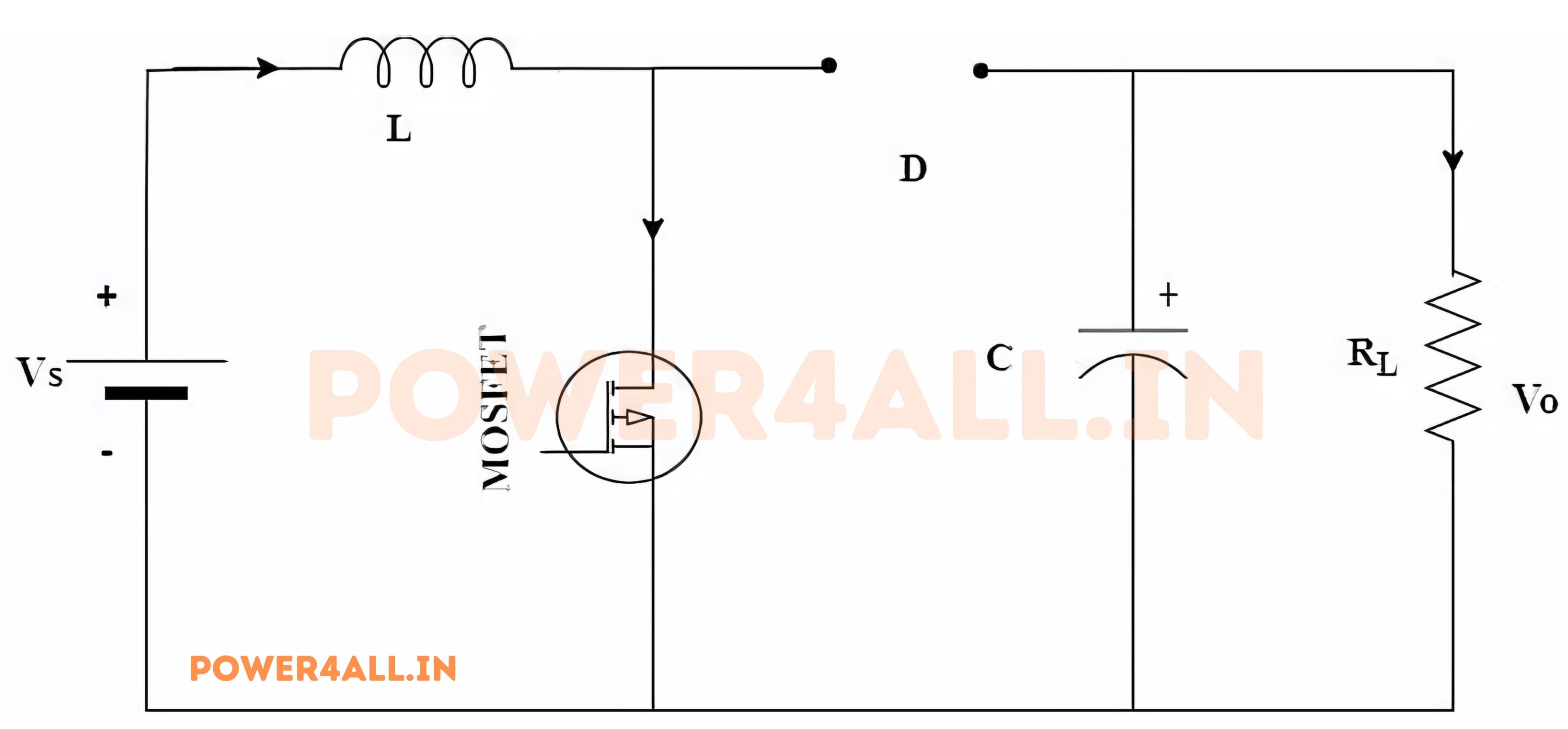
In this operating mode, the inductor's polarity aligns with the current flow direction. The diode D operates in a reverse-biased condition, preventing current flow through the circuit. Consequently, the voltage across the switch S manifests across the load resistance, serving as the output voltage.
Mode II: Switch S is OFF and Diode D is ON
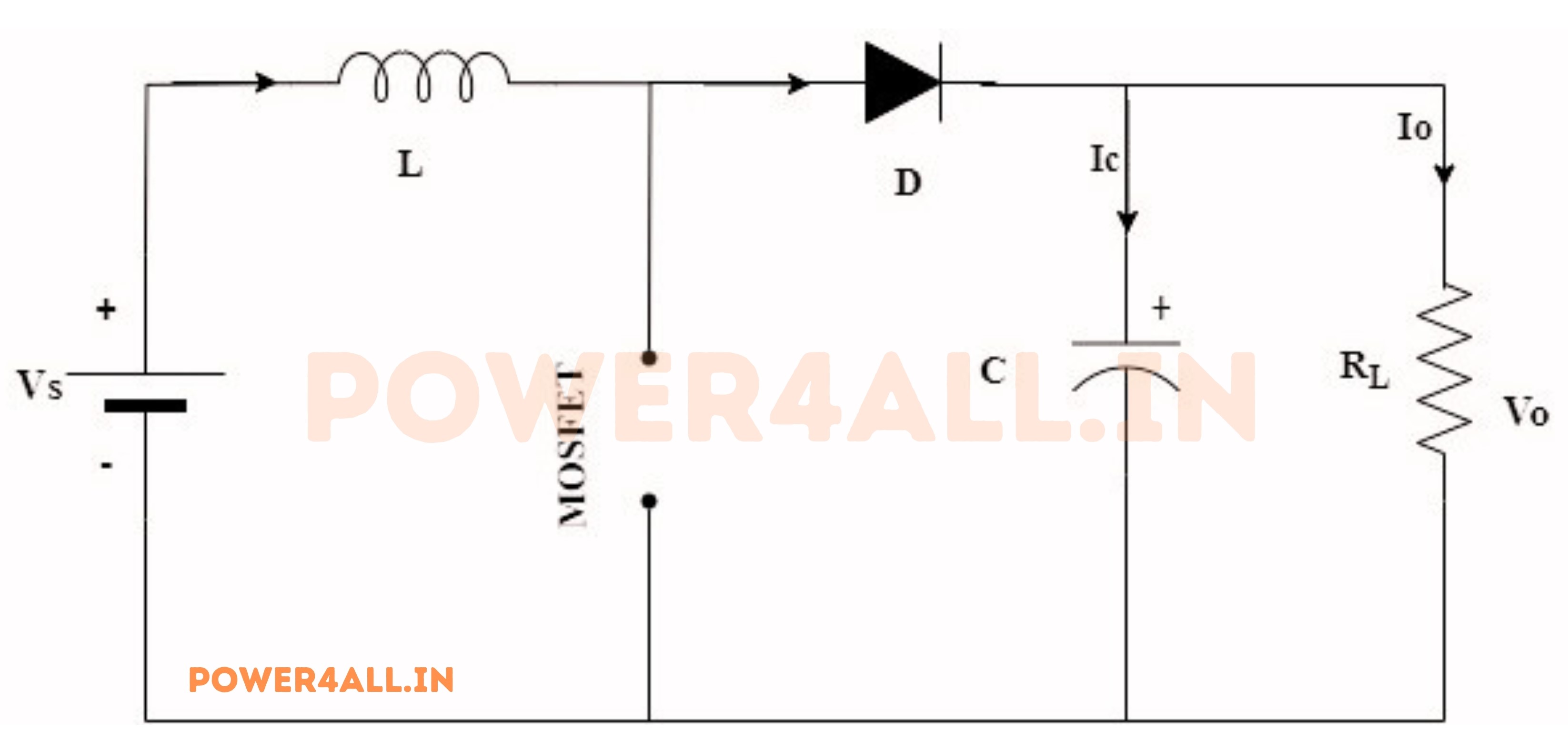
In an electrical circuit, the inductor serves as a storage vessel for energy in the form of a magnetic field, particularly when the switch S is in the open state. Consequently, diode D assumes a closed configuration. The inductor, during this operational phase, discharges the previously stored energy from when the switch S was in the closed state. As the inductor releases its stored energy, its polarity undergoes reversal, thereby inducing forward bias in diode D and permitting the passage of current through the circuit, as illustrated in the accompanying diagram.
The energy released is ultimately dissipated in the load resistance, which helps sustain the current flow in the same direction through the load and boosts the output voltage. The current passing through the inductor gradually decreases and will eventually cease.
The inductor's energy is released to the load, and the output voltage is higher than the input voltage. The output voltage can be controlled by adjusting the duty cycle of the switch S.
The output voltage (Vout) of the boost converter can be calculated using the formula: Vout = Vin / (1 - D) where Vin is the input voltage and D is the duty cycle (the ratio of the time the switch is ON to the total time of one switching cycle). The duty cycle (D) can be expressed as: D = Ton / (Ton + Toff) where Ton is the time the switch is ON and Toff is the time the switch is OFF.
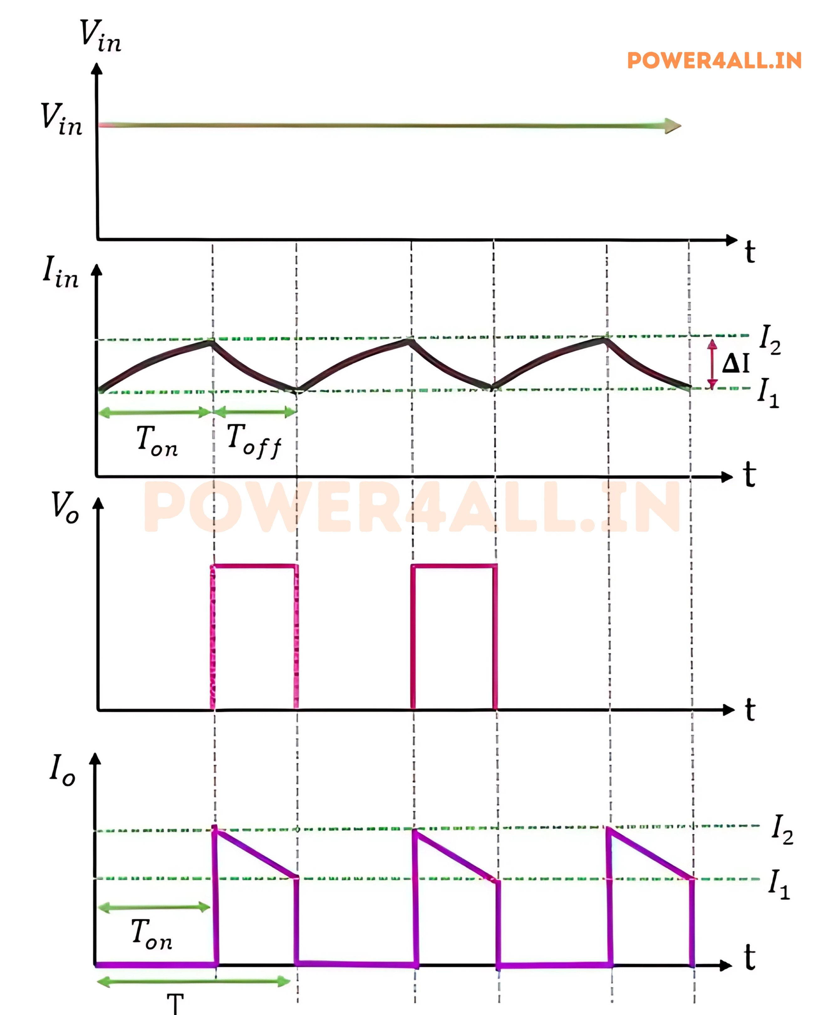
Waveform of Boost Converter
The waveform of a boost converter is characterized by its distinct voltage and current profiles during the two operational modes. The following figure illustrates the voltage and current waveforms associated with the boost converter's operation.
Advantages of Boost Converter
The boost converter offers several advantages, making it a popular choice in various applications:
- Voltage Step-Up
- High Efficiency: Boost converters can achieve high efficiency, typically between 80% and 95%, depending on the design and components used.
- Compact Size: Due to high efficiency and fewer passive components, boost converters can be compact, making them suitable for portable and space-constrained applications.
- Wide Range of Input Voltages: They can operate over a wide range of input voltages, making them versatile for various applications.
- Regulated Output Voltage: Boost converters can provide a stable and regulated output voltage, which is essential for sensitive electronic devices.
Disadvantages of Boost Converter
While boost converters have many advantages, they also have some disadvantages:
- Complex Control: The control circuitry can be complex, especially for applications requiring precise voltage regulation.
- Electromagnetic Interference (EMI): The switching operation can generate EMI, which may affect nearby sensitive circuits.
- Output Ripple: Boost converters can produce output voltage ripple, which may require additional filtering in some applications.
- Limited Current Capability: They may have limitations on the maximum output current, depending on the design and components used.
Applications of Boost Converter
Boost converters find applications in various fields, including:
- Battery-Powered Devices: Used in devices like smartphones, tablets, and laptops to step up battery voltage for efficient operation.
- LED Drivers: Provide the necessary voltage for driving high-brightness LEDs in lighting applications.
- Power Supply Units (PSUs): Used in power supplies to convert lower input voltages to higher output voltages.
- Solar Power Systems: Boost converters are used in solar charge controllers to step up the voltage from solar panels for battery charging.
- Electric Vehicles: Employed in electric vehicles to boost the voltage from the battery pack for motor drive applications.
Conclusion
In conclusion, the boost converter is a highly efficient and versatile DC-DC converter that plays a crucial role in modern power electronics. Its ability to step up voltage while maintaining high efficiency makes it suitable for a wide range of applications, from consumer electronics to renewable energy systems. Understanding its working principle, advantages, and applications is essential for engineers and designers in the field of power electronics.