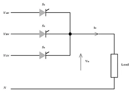
What is a three-phase half-wave controlled (3-pulse) rectifier?
A three-phase half-wave controlled rectifier connects one thyristor (SCR) to each phase, with all three cathodes joined at a common point that feeds the load; the supply neutral is the return. Each SCR is triggered a firing angle α after the instant its phase becomes the most positive — its natural turn-on. Delaying the firing shifts the conduction window and lowers the average output as cos α. Because three devices share the cycle, each conducts for 120° and the output has three humps per cycle (3-pulse). For α > 90° the average goes negative and, with an active load, the converter inverts.
Output voltage, PIV & ripple
Here Vm is the peak phase (line-to-neutral) voltage. At α = 0 the bridge behaves like the uncontrolled 3-pulse rectifier, Vdc = 3√3·Vm/2π ≈ 0.827·Vm; at α = 90° the average output is zero. Each SCR blocks the full line-to-line peak, PIV = √3·Vm. Because it uses only one device per phase, the supply current has a DC component that can saturate the transformer — a drawback the full (6-pulse) bridge avoids.
Two-quadrant operation & inversion
With a highly inductive load the current is continuous and the output follows the fired phase voltage, which swings negative for α > 90°. With an active load (a DC-motor back-EMF or battery — set a negative E) the current keeps flowing and power flows from the DC side to the AC supply: line-commutated inversion. A passive load cannot invert, so its current simply becomes discontinuous at large α — explore both in the simulator.
Advanced options in this simulator
- SCR model: add a forward drop
V_fand on-resistanceR_on; one device conducts at a time, so the drop isV_f + R_on·i. The accuracy check stays locked to the ideal envelope. - Transformer: a turns ratio scales the phase voltage that reaches the SCRs.
- Load configuration: resistive, inductive (R-L) or with a back-EMF (R-L-E, signed for inversion).
- Filter & protection: a series-L, shunt-C or LC output filter, an optional RC snubber, and a live protection-margin check of the SCR PIV and average current against the ratings you enter.
- Phase sequence & imbalance: swap the sequence or unbalance the phases and watch the ripple and harmonics change.
- Harmonic spectrum analysis: a real FFT of the output voltage (3rd, 6th, 9th …) or the SCR current with the ripple / THD figure (relative to |DC| so it works in inversion too).
- Export & capture: download the full waveform data as CSV, a text report, or a PNG screenshot of the scope.
Controlled 3-pulse vs uncontrolled 3-pulse
| Feature | 3-pulse uncontrolled | 3-pulse controlled |
|---|---|---|
| Devices | 3 diodes | 3 thyristors |
| Average voltage | 3√3·Vm/2π (fixed) | (3√3·Vm/2π)cos α (adjustable) |
| Quadrants | 1 (rectify) | 2 (rectify + invert) |
| Ripple frequency | 3f | 3f |
| PIV | √3·Vm | √3·Vm |
See the uncontrolled 3-pulse rectifier for the diode version, or the three-phase full-wave (6-pulse) controlled bridge for the higher-power version.
Applications
Medium-power adjustable DC supplies, DC-motor speed control and battery charging where a three-phase supply is available. For higher power, lower ripple and no transformer DC, the 6-pulse fully-controlled bridge is preferred.
Frequently asked questions
What is the average output voltage of a 3-pulse controlled rectifier?
Vdc = (3√3·Vm/2π)cos α ≈ 0.827·Vm·cos α in continuous conduction, where Vm is the phase peak. Maximum at α = 0, zero at α = 90°.
What happens for α greater than 90 degrees?
The average output voltage becomes negative. With an active load the converter inverts — power flows from DC back to the AC supply. Use the Inversion preset with a negative back-EMF.
What is the PIV of each thyristor?
PIV = √3·Vm — the peak line-to-line voltage.
Which harmonics appear?
Output-voltage harmonics at multiples of 3× the supply frequency (3rd, 6th, 9th …). Raising α increases the harmonic content. Toggle the spectrum panel between output voltage and SCR current.
What causes discontinuous conduction?
A resistive or lightly-inductive load lets the current fall to zero between firings, especially at large α. The simulator flags continuous (CCM) or discontinuous (DCM) conduction and only compares against the (3√3·Vm/2π)cos α formula in CCM.