Single-Phase Full-Wave Uncontrolled Rectifier
A single-phase full-wave uncontrolled rectifier uses diodes to convert both halves of an AC signal into DC output.
Introductiont
A full-wave rectifier is a rectification device that transforms both the positive and negative halves of each cycle of an alternating wave (AC signal) into a pulsating direct current (DC) signal. This type of rectifier is commonly employed to convert AC voltage to DC voltage and necessitates the use of multiple diodes in its construction. Full-wave rectification is the process of changing an AC signal into a DC signal.
Rectifiers are electronic circuits designed to convert alternating current (AC) into direct current (DC). Full-wave rectifiers are specifically engineered to convert both the positive and negative half cycles of an AC waveform.
Full-wave rectification is achieved through the utilization of a diode bridge, which consists of a combination of diodes. Each diode allows the flow of current in one direction and prevents it in the opposite direction. This fundamental principle is leveraged in the construction of various rectifier circuits.
Full wave rectifiers are further classified into:
- Center-Tapped Full-Wave Rectifier
- Bridge Full-Wave Rectifier
Centre-tapped Full Wave Rectifier
A single-phase centre-tapped full wave rectifier uses a transformer with a center tap and two diodes. Each diode conducts during alternate half-cycles of the AC input, so both halves of the AC signal are used to produce a smoother DC output across the load. This setup is more efficient than a half-wave rectifier but requires a center-tapped transformer.
Construction of Centre-tapped Full Wave Rectifier
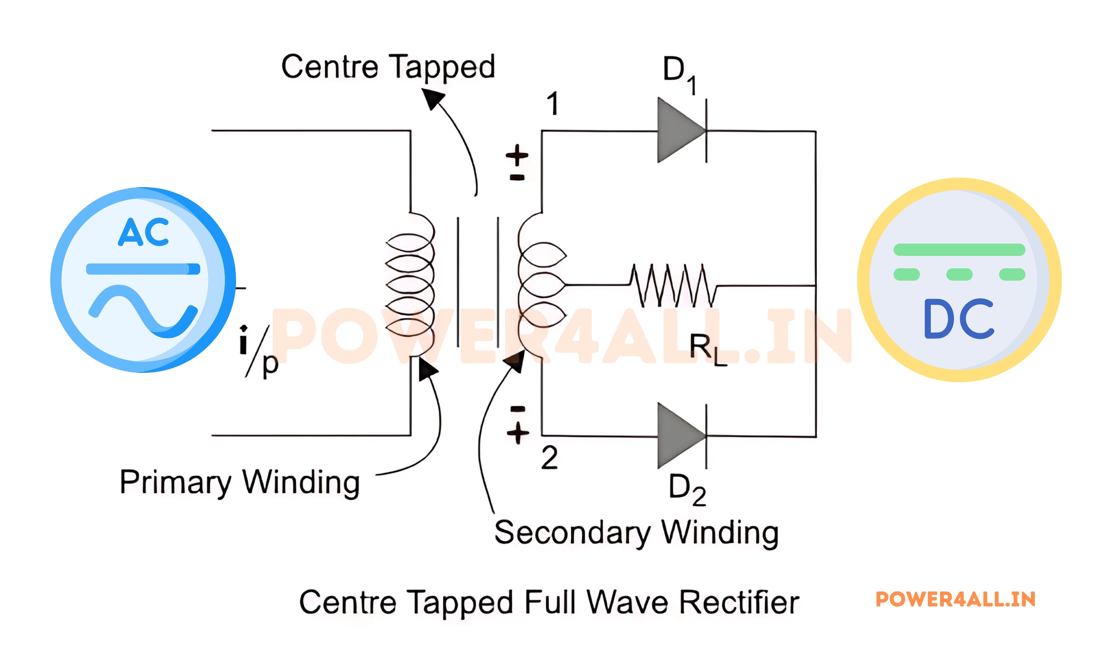
A centre-tapped full-wave rectifier system consists of:
- Centre-tapped Transformer
- Two Diodes
- Resistive Load
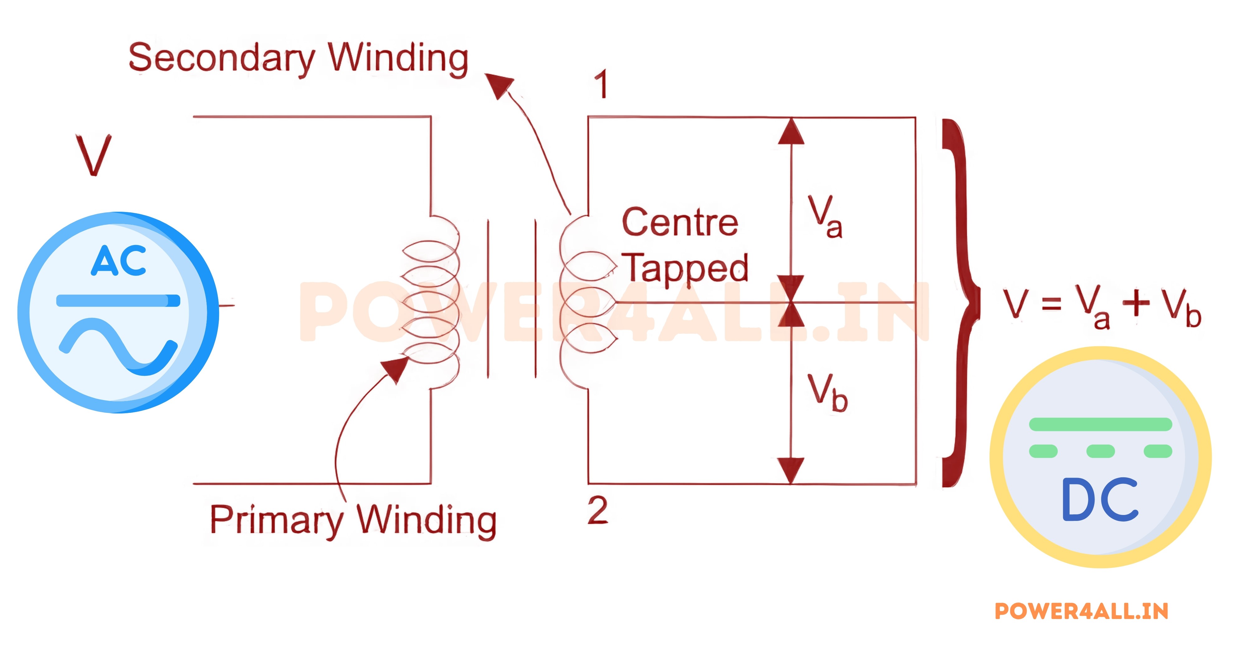
In a Centre-tapped Transformer, a standard transformer undergoes a minor modification by incorporating an additional wire connected to the precise center of the secondary winding. This construction effectively divides the AC voltage into two equal and opposite voltages, known as positive voltage (Va) and negative voltage (Vb). The total output voltage is then expressed as V=Va+Vb.
Working of Half Wave Uncontrolled Rectifier
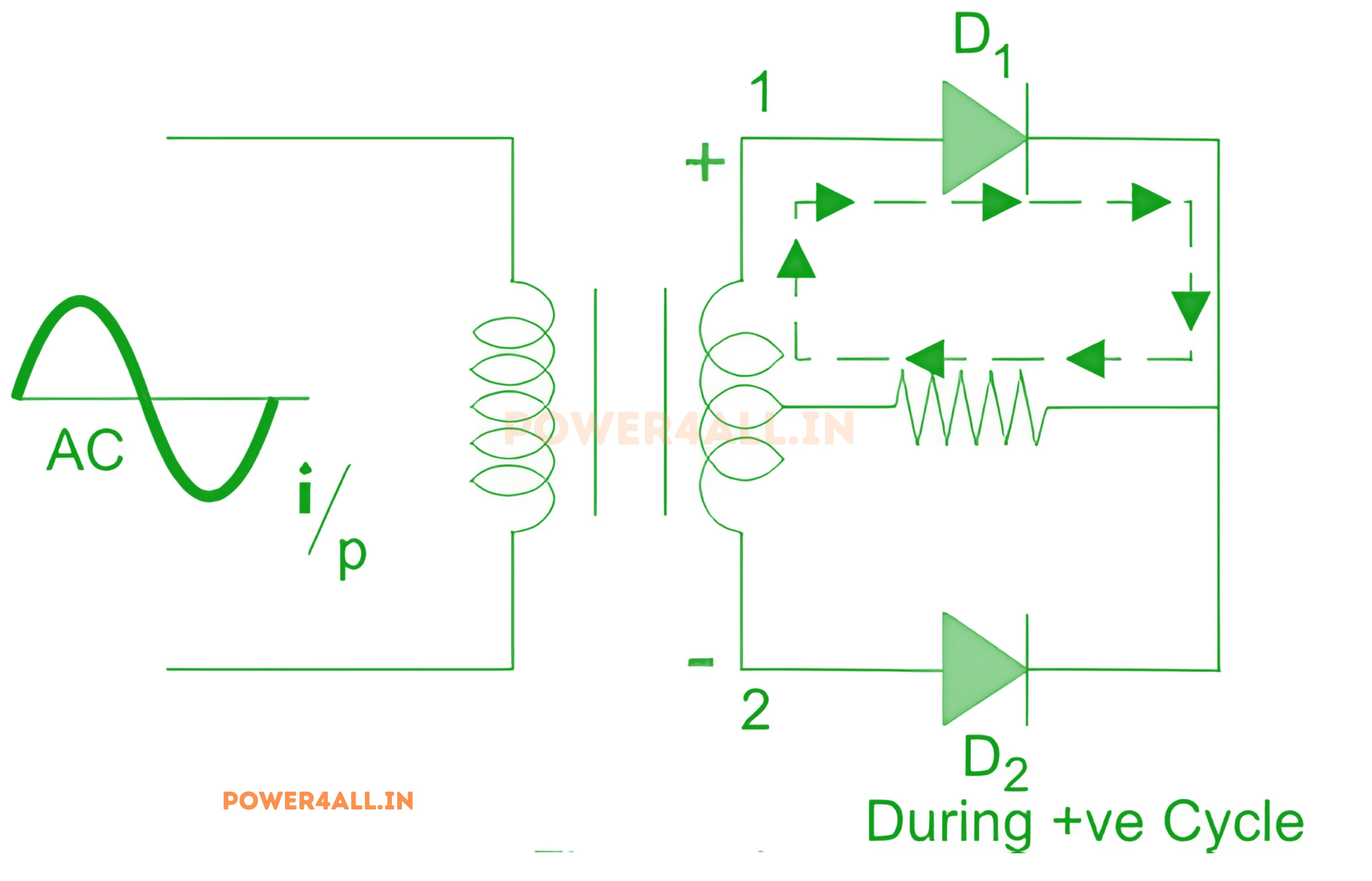
Mode-1 when Diode is forward-biased
An alternating current (AC) voltage is applied to the input transformer. During the positive half-cycle of the AC voltage, terminal 1 exhibits positive potential, the center-tap remains at zero potential, and terminal 2 demonstrates negative potential.
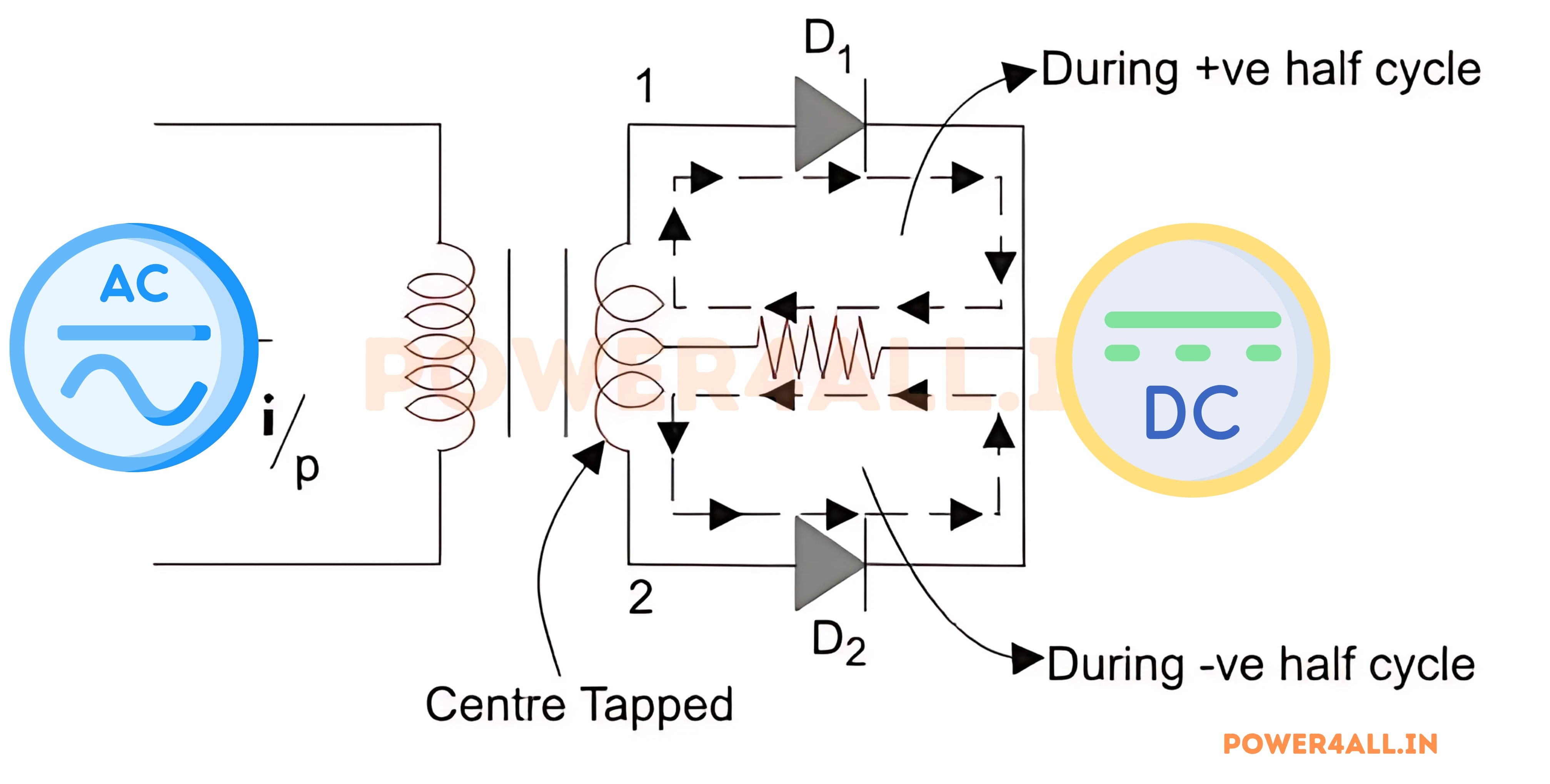
During this period, diode D1 undergoes forward bias, facilitating the flow of current through it. Meanwhile, diode D2 experiences reverse bias, effectively preventing the passage of current.
During the negative half-cycle of the input AC voltage, terminal 2 will become positive relative to terminal 1 and the center tap. This will lead to forward bias in diode D2, causing current to flow through it. At the same time, diode D1 will be in reverse bias and will block current through it.
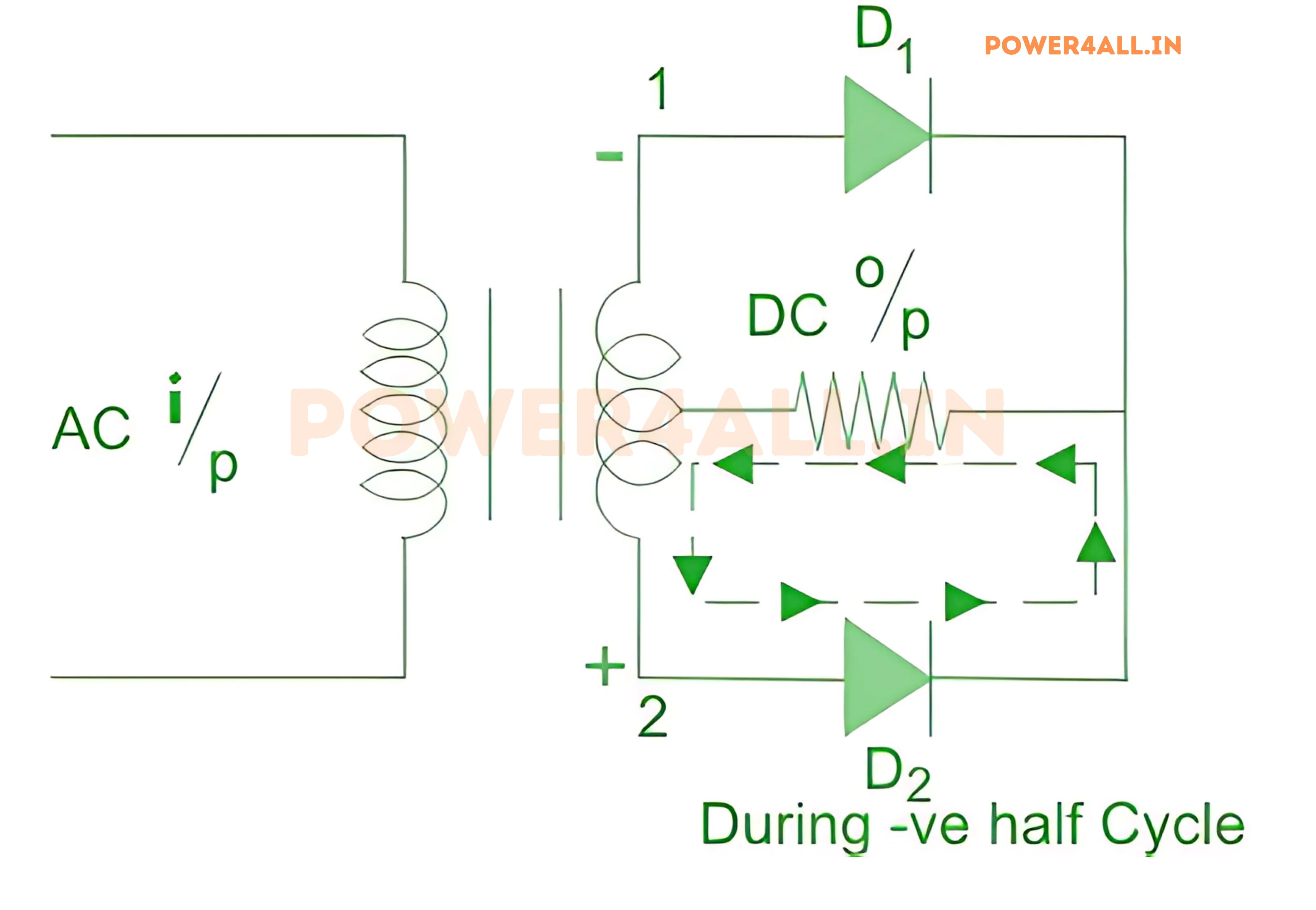
During the positive cycle, diode D1 conducts, while diode D2 conducts during the negative cycle. Consequently, both half-cycles are permitted to pass through, resulting in the average output DC voltage approaching twice the DC output voltage of a half-wave rectifier.
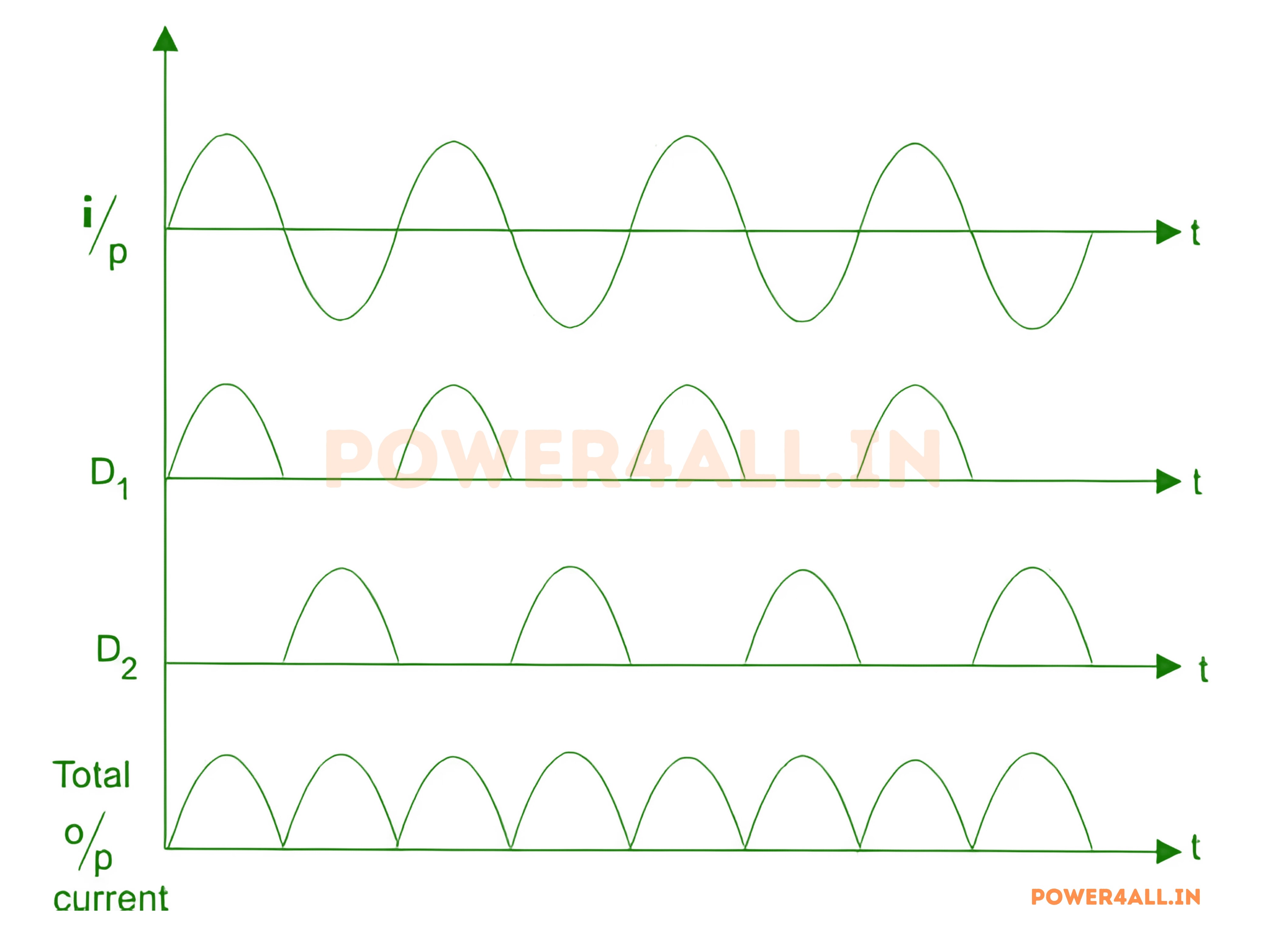
Waveform of Centre-tapped Full Wave Rectifier
Full Wave Bridge Rectifier
Construction of Full Wave Bridge Rectifier
A full-wave bridge rectifier is a rectification circuit comprising four diodes arranged in a bridge configuration. The essential components of a full-wave bridge rectifier system are as follows:
- Four Diodes
- TResistive Load
- Transformer (optional)
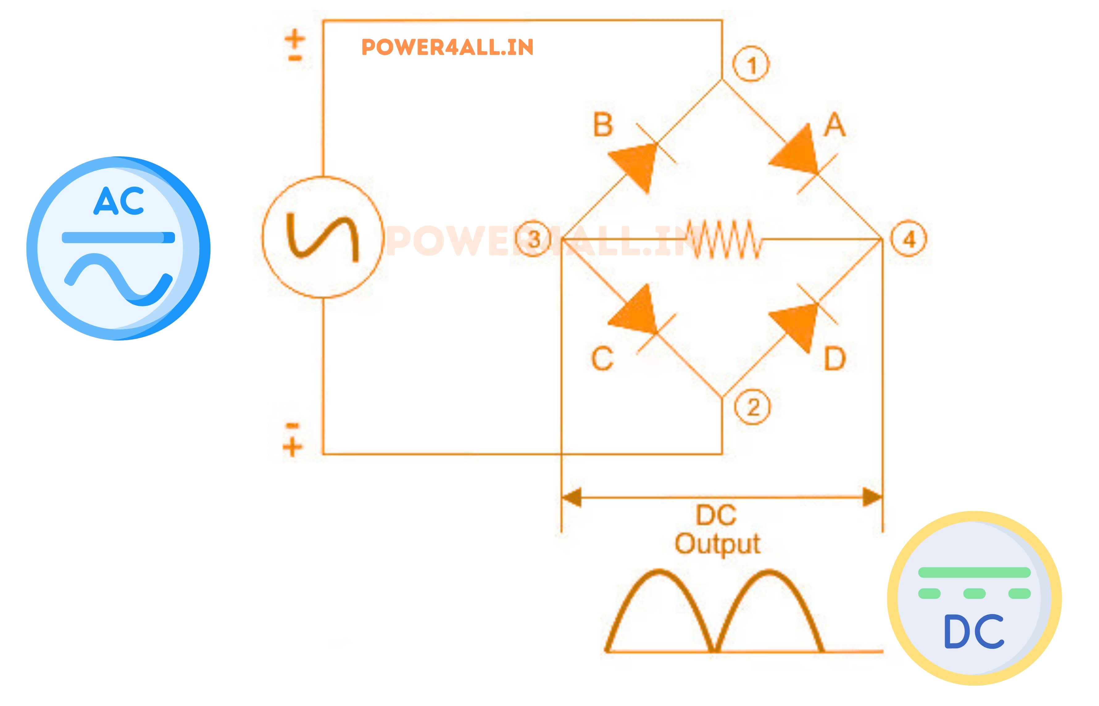
The diodes, denoted as A, B, C, and D, are interconnected to form a bridge circuit, as illustrated in the accompanying diagram.
Working Principle of Full Wave Bridge Rectifierr
When an alternating current (AC) is applied across the bridge, terminal 1 becomes positive and terminal 2 becomes negative during the positive half-cycle.
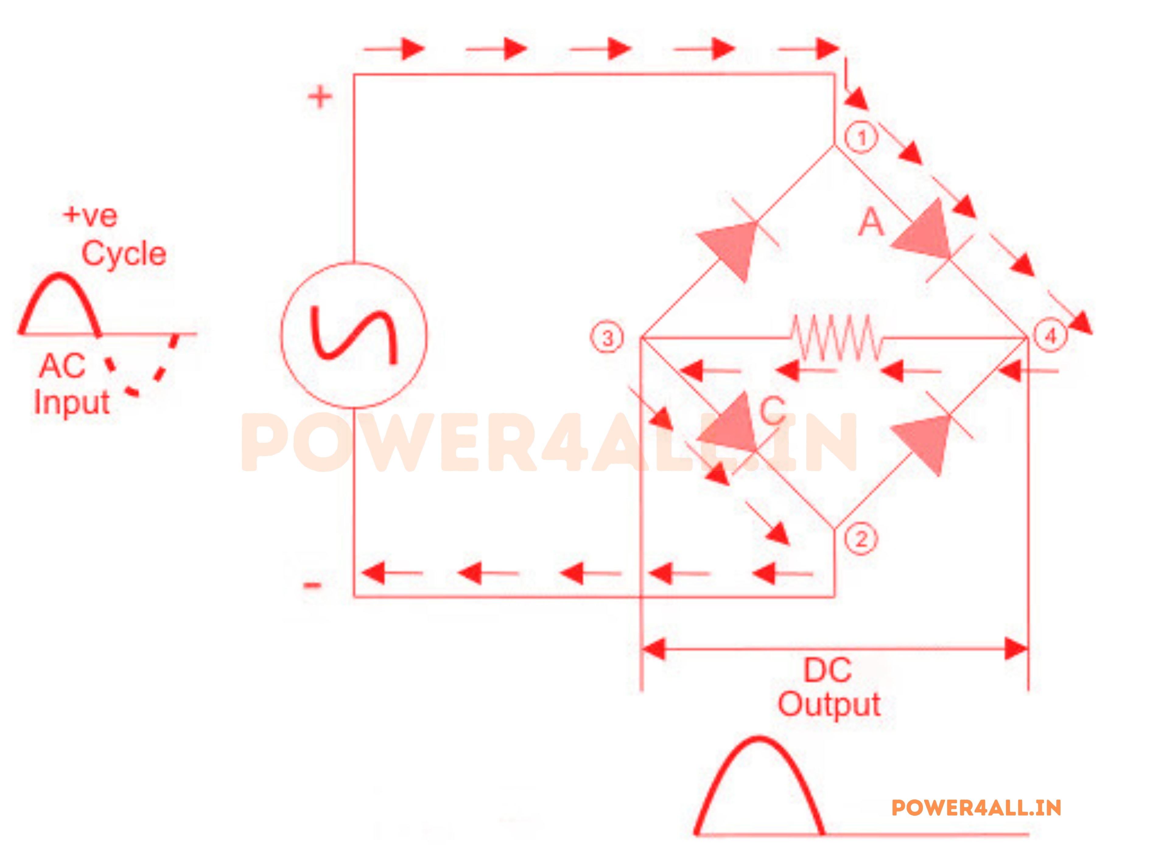
When the appropriate current is applied to the circuit, diodes A and C undergo forward biasing, allowing the current to traverse through them. Simultaneously, diodes B and D undergo reverse biasing, impeding the passage of current. The current follows a path from point 1 to point 4, then to point 3, and finally to point 2.
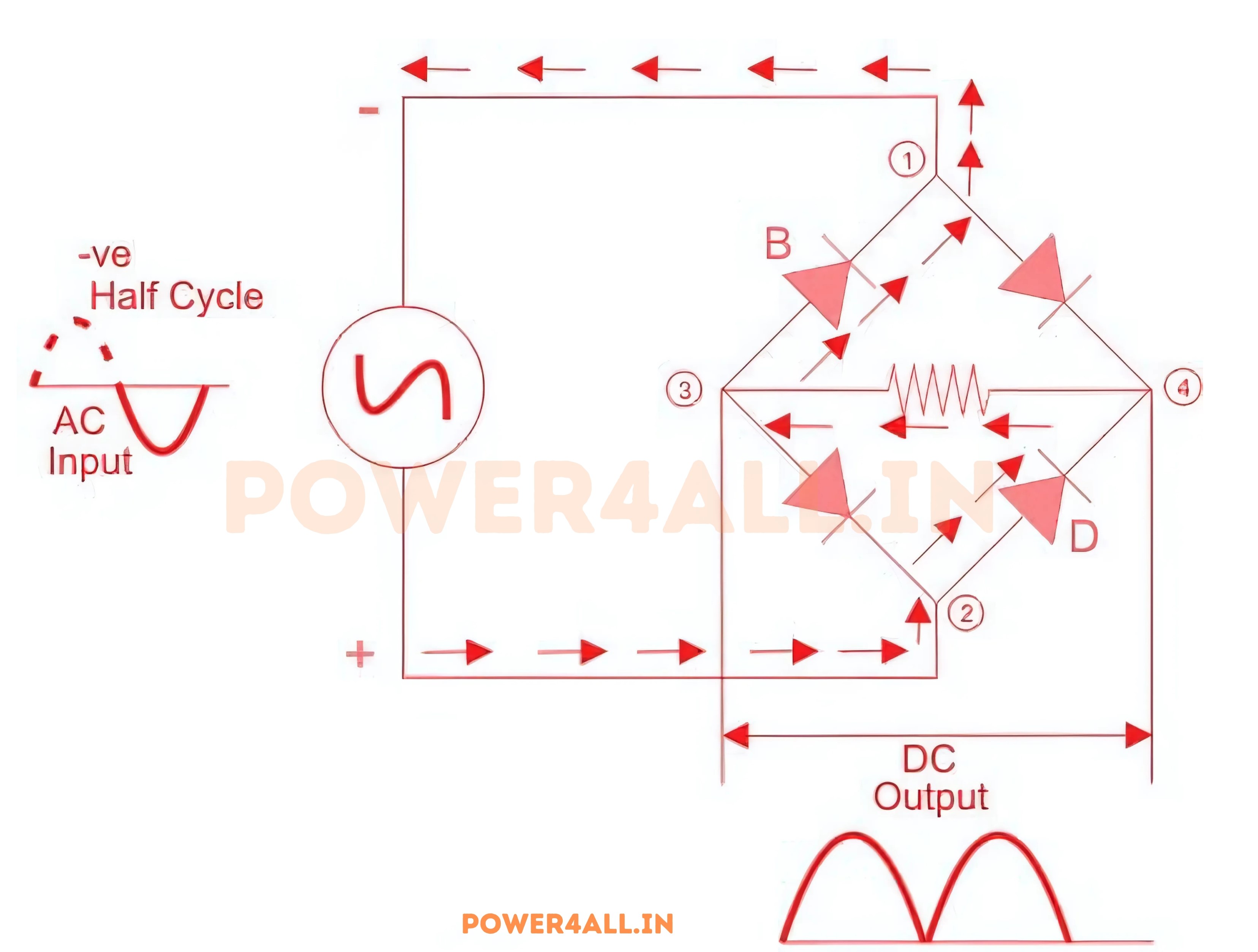
Throughout the negative half-cycle, terminal 1 assumes a negative potential, while terminal 2 assumes a positive potential.
When the circuit is operational, diodes B and D undergo forward bias, enabling the passage of current. In contrast, diodes A and C are reverse-biased, impeding current flow. Consequently, the current proceeds from point 2 to 4, then to 3, and finally to 1.
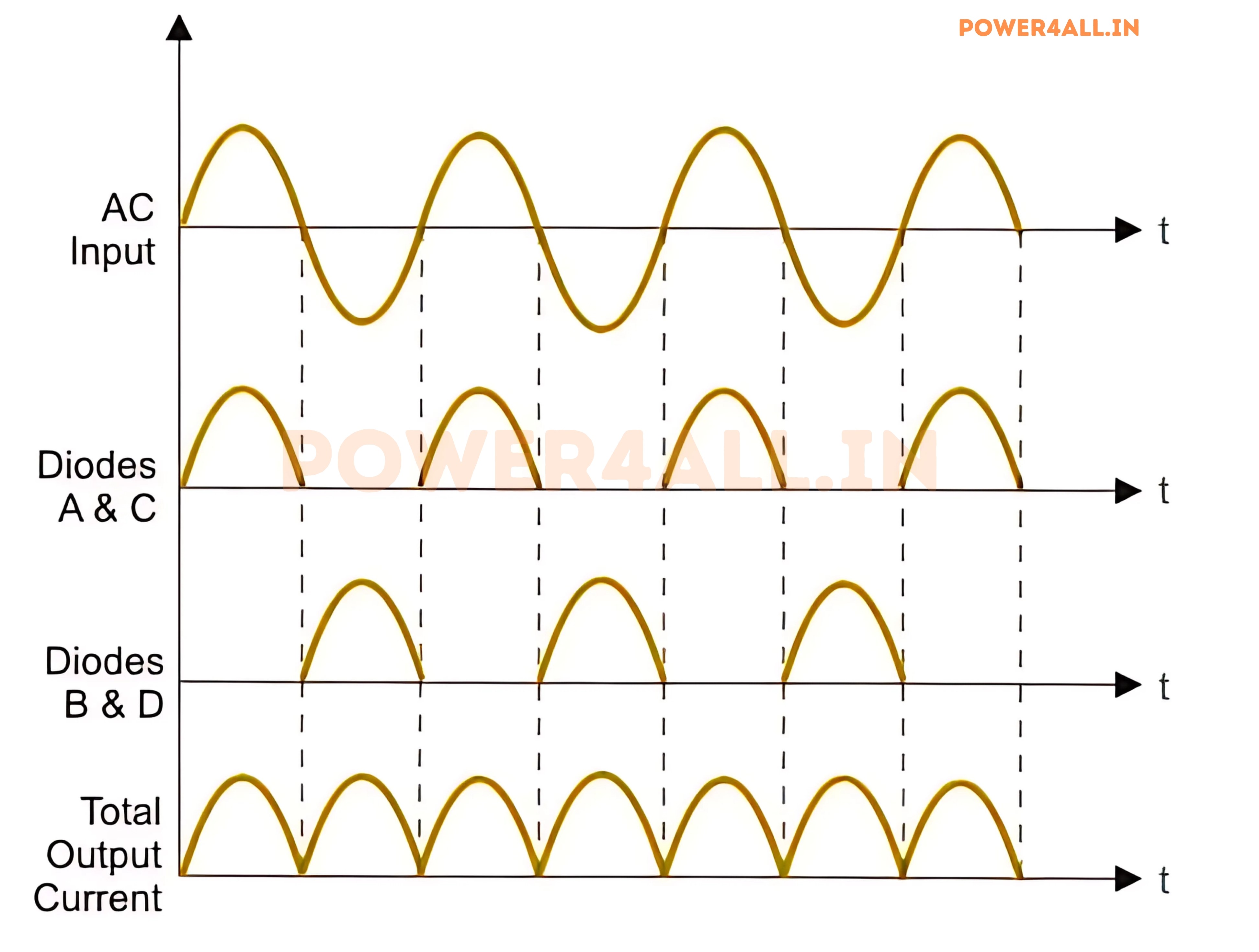
Waveform of Bridge Rectifier
Advantages of Full Wave Rectifiers
- Full-wave rectifiers exhibit superior rectifying efficiency when compared to half-wave rectifiers. Consequently, they are more effective in converting AC to DC.
- The power loss in these systems is minimal due to the efficient utilization of voltage signals in the rectification process.
- The output voltage of a center-tapped full-wave rectifier exhibits reduced ripple compared to that of a half-wave rectifier.
Disadvantages of Full Wave Rectifiers
- The center-tapped rectifier is a costlier alternative compared to the half-wave rectifier and often requires a larger physical footprint.