Buck-Boost Converter
The primary function of a buck-boost converter is to step up or step down voltage from a lower level to a higher level.
- Introduction
- DC-DC BUCK-BOOST CONVERTER
- Working Principle of buck-boost Converter
- Mode-1 when Diode is forward-biased
- Mode-2 when Diode is reverse-biased
- Waveform of buck-boost Converter
- Advantages of buck-boost Converter
- Disadvantages of buck-boost Converter
- Applications of buck-boost Converter
- Conclusion
- Frequently Asked Questions About buck-boost Converter – FAQs
- Related Topics
Introduction
When your power needs are flexible but your voltage source isn't, the buck-boost converter steps in to save the day. This versatile circuit can both increase and decrease DC voltage levels, making it the Swiss Army knife of power conversion. Whether you're dealing with fluctuating battery voltages or need multiple output levels from a single source, the buck-boost converter handles these challenges with remarkable efficiency.
Buck-boost converters really shine in battery-powered applications where voltage naturally drops during discharge. Think about your phone or laptop - as the battery drains from 4.2V down to 3V, the circuits still need a steady 3.3V or 5V to operate properly. That's where these converters earn their keep, automatically adjusting to maintain stable output regardless of input fluctuations. They're not the simplest converters to design, but their flexibility makes them worth every component on the board when you need that adaptable power solution.
Buck-boost converters are widely used in various applications, including battery-powered devices, LED drivers, and power supply units. They are essential for providing stable voltage levels in systems where the input voltage may vary significantly.
DC-DC BUCK-BOOST CONVERTER
The Buck-Boost Converter is a DC-to-DC converter that can produce an output voltage greater or less than the input voltage.
The magnitude of the output voltage is contingent upon the duty cycle. Referred to as both step-up and step-down transformers, these converters work to elevate or reduce input voltages as needed. Notably, through the efficient conversion of energy, the input power equates to the output power according to a specific formula.
The buck-boost converter is a type of DC-to-DC converter that can produce an output voltage with a magnitude that may be greater or less than the magnitude of the input voltage. Similar to the flyback circuit, it utilizes a single inductor in place of a transformer. The buck-boost converter incorporates two types of converters: the buck converter and the boost converter. These converters have the capacity to yield an output voltage range wider than that of the input voltage.
Working Principle of Buck-Boost Converter
The operational principle of the buck-boost converter involves the utilization of an inductor in the input resistance, which may result in unanticipated fluctuations in the input current. When the switch is in the on position, the inductor draws energy from the input and accumulates it as magnetic energy. Conversely, when the switch is in the off position, the inductor discharges the accumulated energy.
The output circuit features a capacitor with a sufficiently high capacitance, ensuring that the time constant of an RC circuit in the output stage exceeds the timing of the switching period. This prolonged time constant, in comparison with the switching period, guarantees that the output voltage remains constant during steady state, denoted as Vo(t) = Vo(constant), at the load terminal.
Circuit diagram of Buck-Boost converter is shown in the figure below.
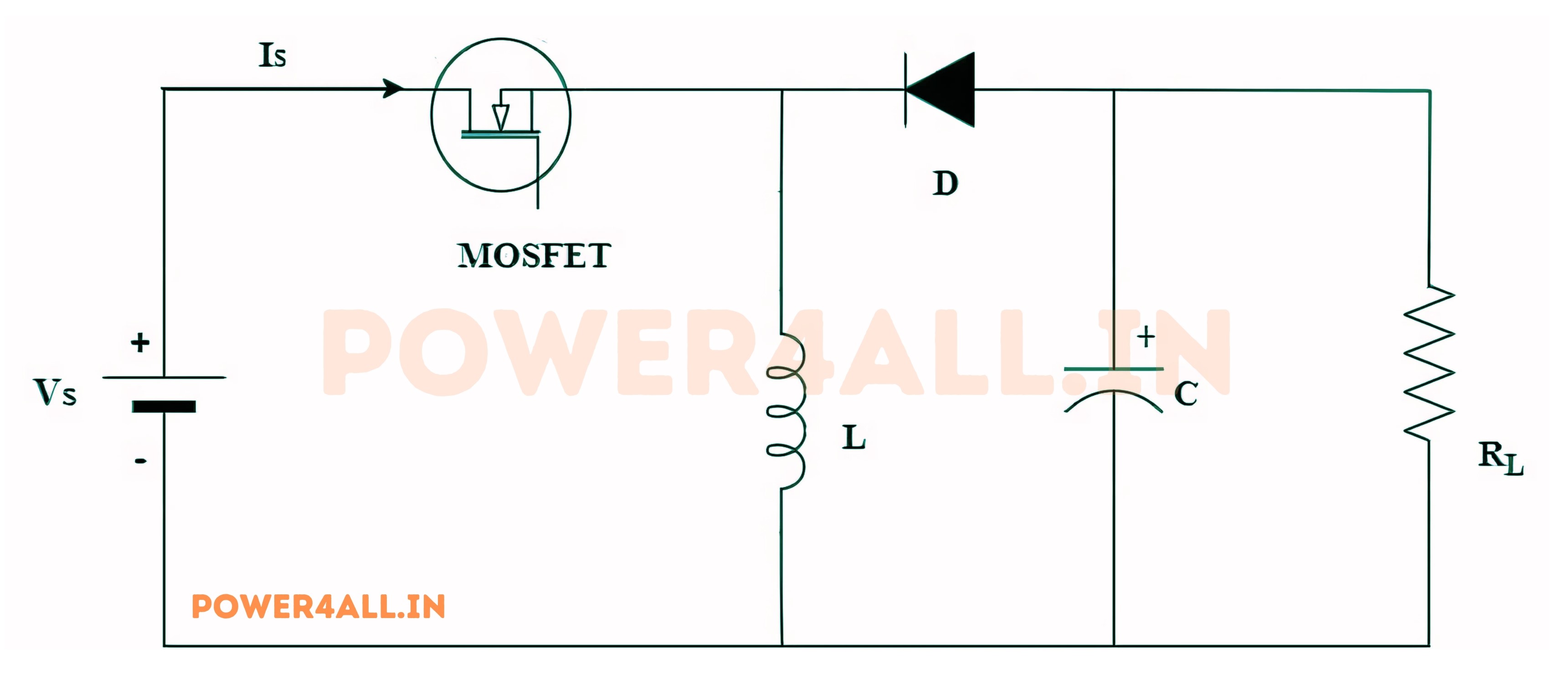
The input voltage source is connected to a solid-state device. The second switch utilized is a diode. The diode is connected in reverse to the direction of power flow from the source to a capacitor and the load, both of which are connected in parallel as illustrated in the figure above.
The controlled switch in the converter utilizes Pulse Width Modulation (PWM) to alternate between on and off states. PWM can be implemented based on time or frequency, with the time-based method being more widely used.
Frequency-based modulation, despite its versatility, presents a drawback in that it necessitates a wide spectrum of frequencies for precise control of the switch, thereby attaining the desired output voltage.
Time-based modulation is commonly employed in the realm of DC-DC converters due to its straightforward implementation and operational ease. In this particular flavor of PWM modulation, the frequency remains constant. The Buck-Boost converter is characterized by two distinct modes of operation, with the initial mode being active when the switch is in an on state and conducting.
There are two modes of operation of the Buck-Boost converter.
Mode I: Switch S is ON and Diode D is OFF
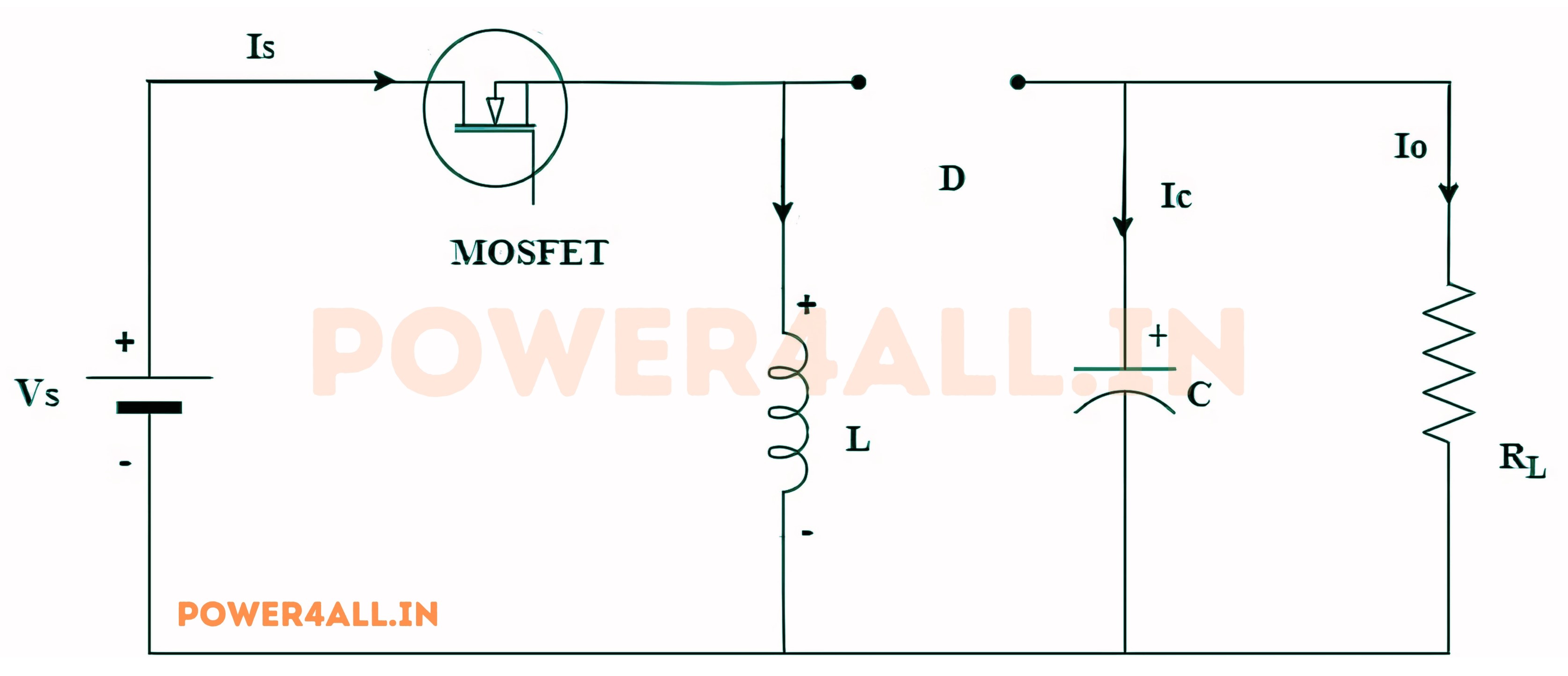
When the switch is in the ON position, it facilitates a short circuit, providing minimal resistance to the flow of current. Consequently, all current will pass through the switch and the inductor before returning to the DC input source.
The inductor functions by storing charge when the switch is in the ON position. Upon the transition to the OFF position, the inductor's polarity undergoes reversal, facilitating the uninterrupted flow of current through the load, diode, and back to the inductor. As a result, the direction of current through the inductor remains consistent.
Mode II: Switch S is OFF and Diode D is ON
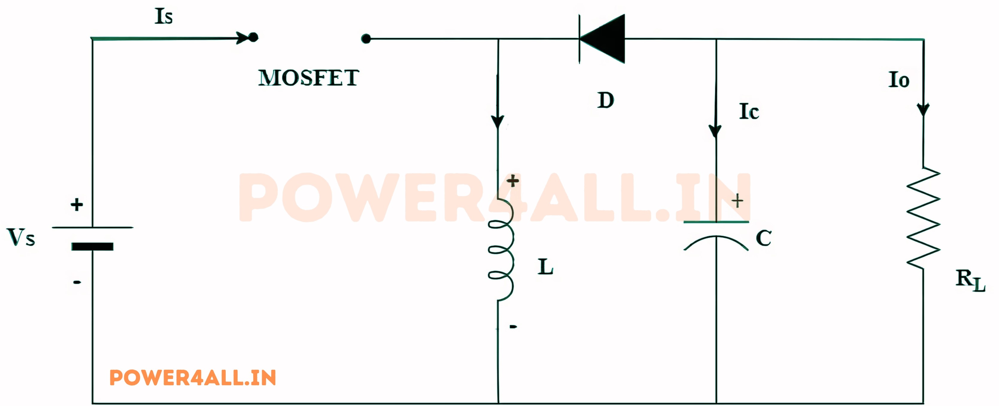
In this operating mode, the polarity of the inductor is reversed, causing the stored energy in the inductor to be released. This released energy is then dissipated in the load resistance, which helps to sustain the current flow in the same direction through the load. Additionally, this process results in an increase in the output voltage, as the inductor now acts as a source alongside the input source. Despite these changes, we adhere to the original conventions for circuit analysis using KVL.
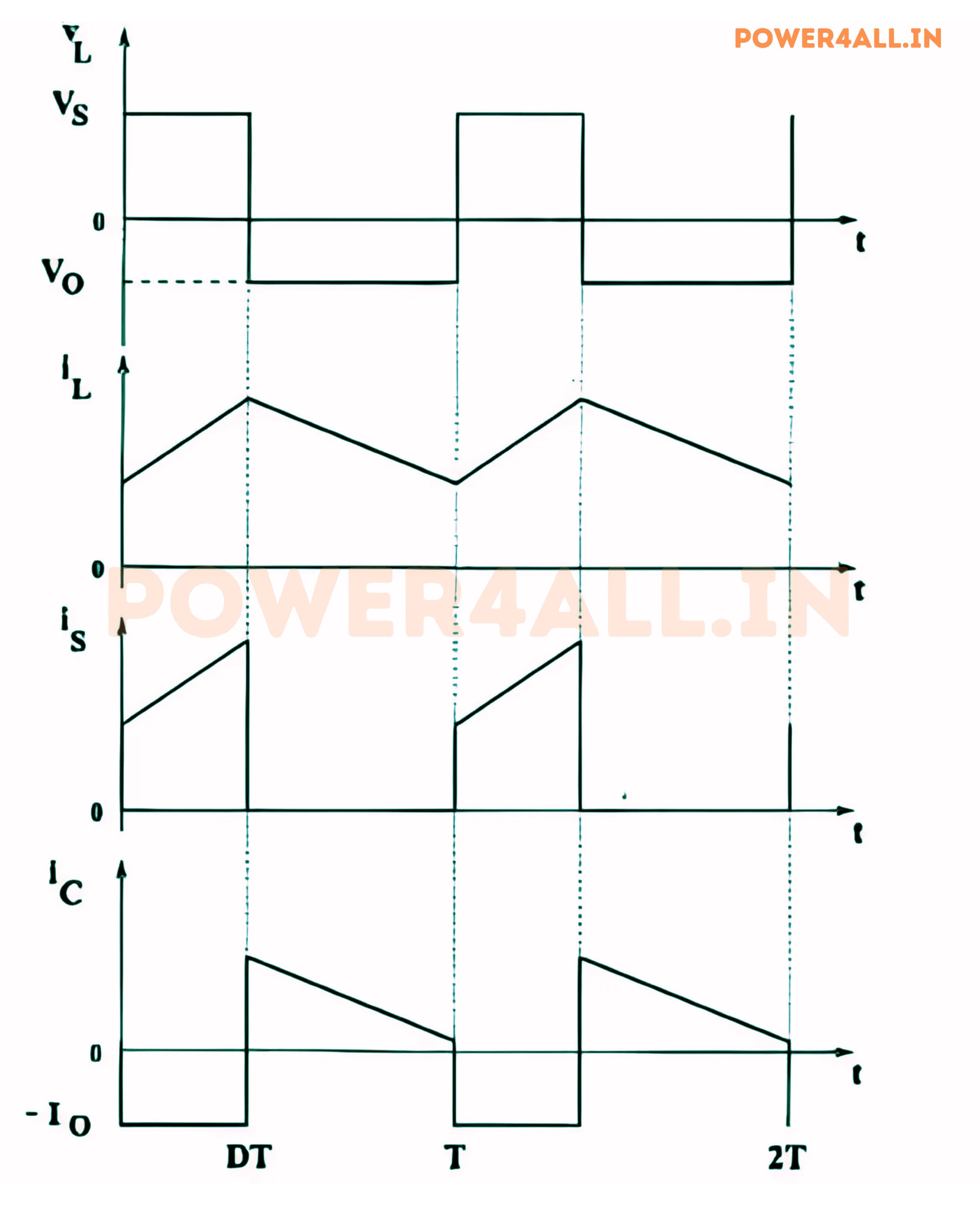
Waveform of Buck-Boost Converter
The waveform of a buck-boost converter is characterized by its distinct voltage and current profiles during the two operational modes. The following figure illustrates the voltage and current waveforms associated with the buck-boost converter's operation.
Advantages of Buck-Boost Converter
The buck-boost converter offers several advantages, making it a popular choice in various applications:
- Versatility: It can step up or step down voltage levels, making it suitable for a wide range of applications.
- High Efficiency: Buck-boost converters can achieve high efficiency, especially when designed with high-quality components.
- Compact Size: They can be designed to be compact and lightweight, making them ideal for portable applications.
- Wide Input Voltage Range: Buck-boost converters can operate over a wide input voltage range, providing flexibility in design.
- Low Output Ripple: With proper design, they can produce low output voltage ripple, ensuring stable operation of connected loads.
Disadvantages of Buck-Boost Converter
While buck-boost converters have many advantages, they also have some disadvantages:
- Complex Control: The control circuitry can be more complex compared to simpler converters, requiring careful design and tuning.
- Higher Component Count: They may require more components than simpler converters, which can increase cost and complexity.
- Electromagnetic Interference (EMI): The switching operation can generate EMI, which may require additional filtering measures.
- Limited Output Current: In some designs, the output current may be limited compared to other converter types.
- Voltage Stress on Components: Components may experience higher voltage stress, requiring careful selection of components to avoid failure.
Applications of Buck-Boost Converter
Buck-boost converters find applications in various fields, including:
- Battery-Powered Devices: Used in devices where the input voltage may vary, such as smartphones and laptops.
- LED Drivers: Provide constant current to LEDs, ensuring consistent brightness.
- Power Supply Units: Used in power supply designs to provide stable output voltage levels.
- Solar Power Systems: Used in solar charge controllers to manage battery charging.
- Electric Vehicles: Employed in electric vehicles for voltage regulation and energy management.
Conclusion
In conclusion, the buck-boost converter is a highly efficient and versatile DC-DC converter that plays a crucial role in modern power electronics. Its ability to step up or step down voltage while maintaining high efficiency makes it suitable for a wide range of applications, from consumer electronics to renewable energy systems. Understanding its working principle, advantages, and applications is essential for engineers and designers in the field of power electronics.