Single-Phase Half-Wave Uncontrolled Rectifier
A fundamental AC to DC converter using a single diode, ideal for low-power applications and teaching the basics of rectification.
Introductiont
Uncontrolled rectifiers are basic circuits in power electronics that change alternating current (AC) into direct current (DC) using diodes. There are two main types of rectifiers: single-phase and three-phase. Single-phase rectifiers can be either half-wave or full-wave. This article focuses on single-phase half-wave uncontrolled rectifiers and explains how they work with resistive (R) and resistive-inductive (RL) loads.
An uncontrolled rectifier is a device that uses diodes to change alternating current (AC) into direct current (DC). Diodes let electricity flow in only one direction. Unlike controlled rectifiers, which can adjust the output voltage using thyristors or SCRs, the output voltage of an uncontrolled rectifier stays fixed once designed. Because they are simple, low-cost, and reliable, uncontrolled rectifiers are great for battery charging, small power supplies, and household appliances.
Single-Phase Half-Wave Uncontrolled Rectifier Circuit
Below is the circuit diagram of the half-wave rectifier. The components of the half-wave rectifier include the P-N junction diode, AC power supply, and the load.
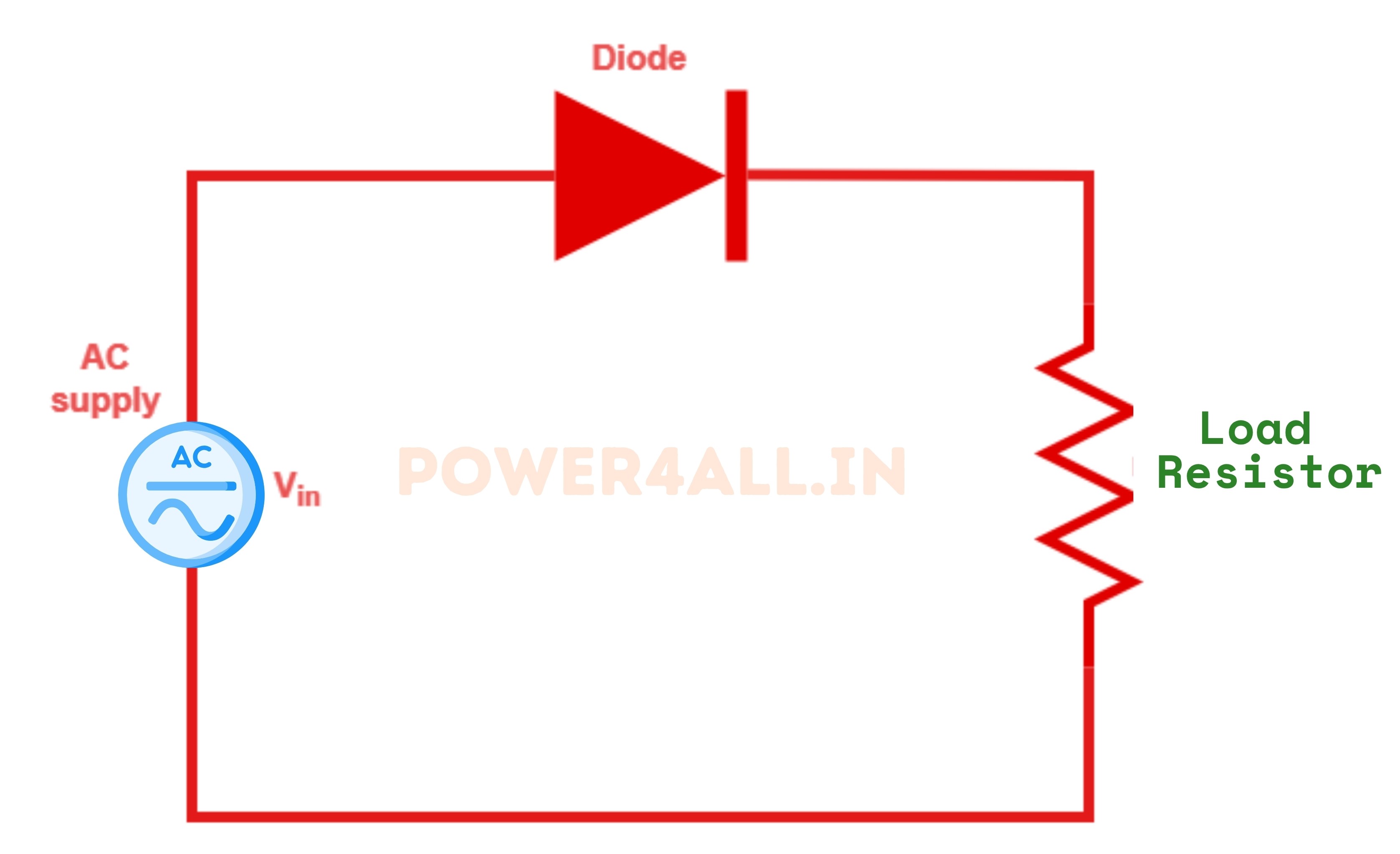
- AC Source: Provides the input voltage.
- Diode (D): Conducts during the positive half-cycle, blocks during the negative half-cycle.
- Load Resistor (RL): Receives the rectified output.
Working of Half Wave Uncontrolled Rectifier
Mode-1 when Diode is forward-biased
In a half-wave rectifier, the alternating current (AC) supply is connected in series with a p-n junction diode and a load resistor. It is important to note that an AC comprises two distinct half-cycles: the positive half-cycle and the negative half-cycle. For a comprehensive understanding of the half-wave circuit, it is necessary to analyze the operation during each half-cycle separately.
During the positive half-cycle, the diode is forward-biased and conducts current, allowing it to flow through the load resistor.
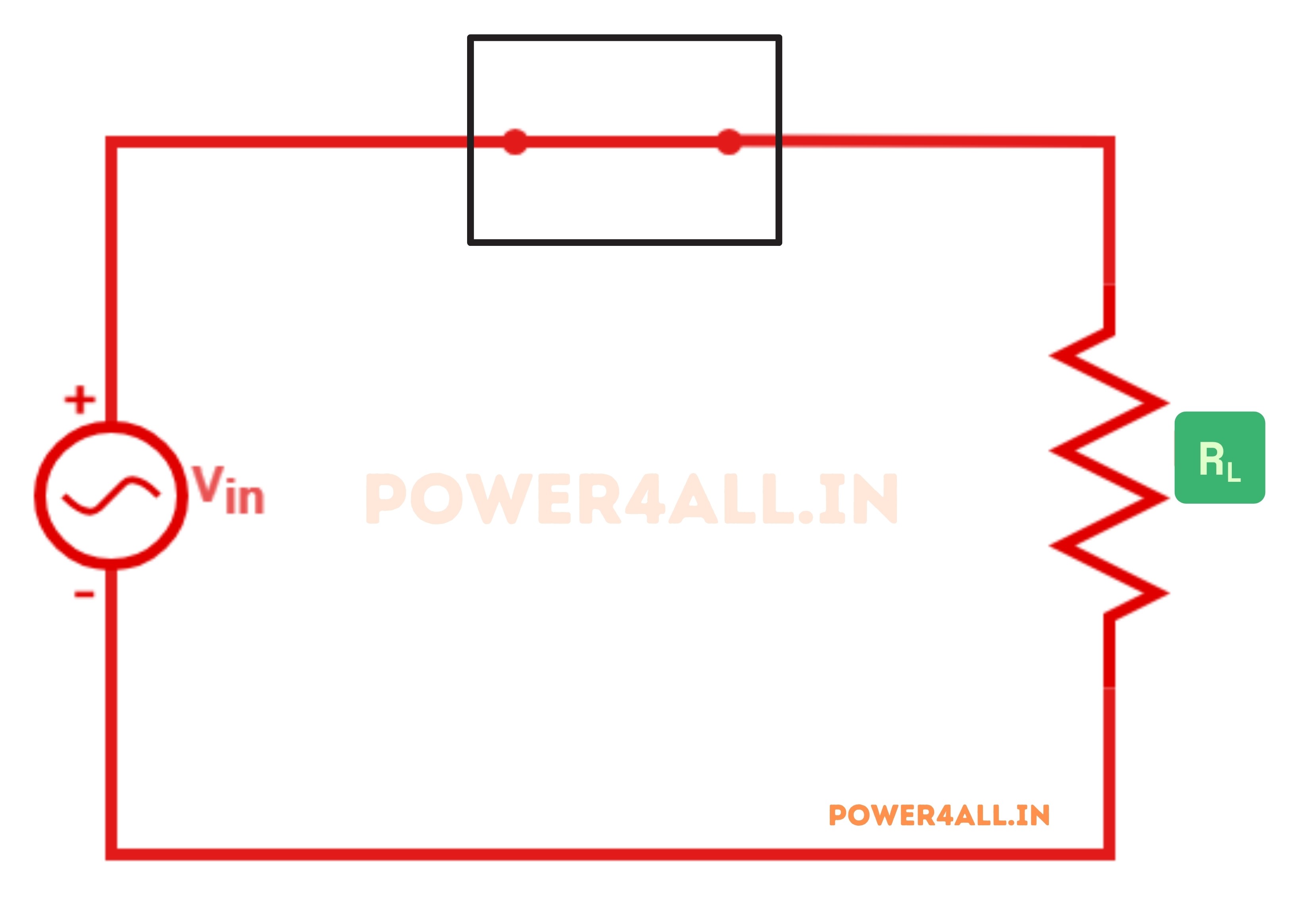
In the above figure, the diode is forward-biased and conducts current, allowing it to flow through the load resistor.
Mode-2 when Diode is reverse-biased
During the negative half-cycle, the diode is reverse-biased and functions as an open circuit. Consequently, no current passes through the circuit in the negative half-cycle, resulting in the absence of the input's negative half-cycle in the output.
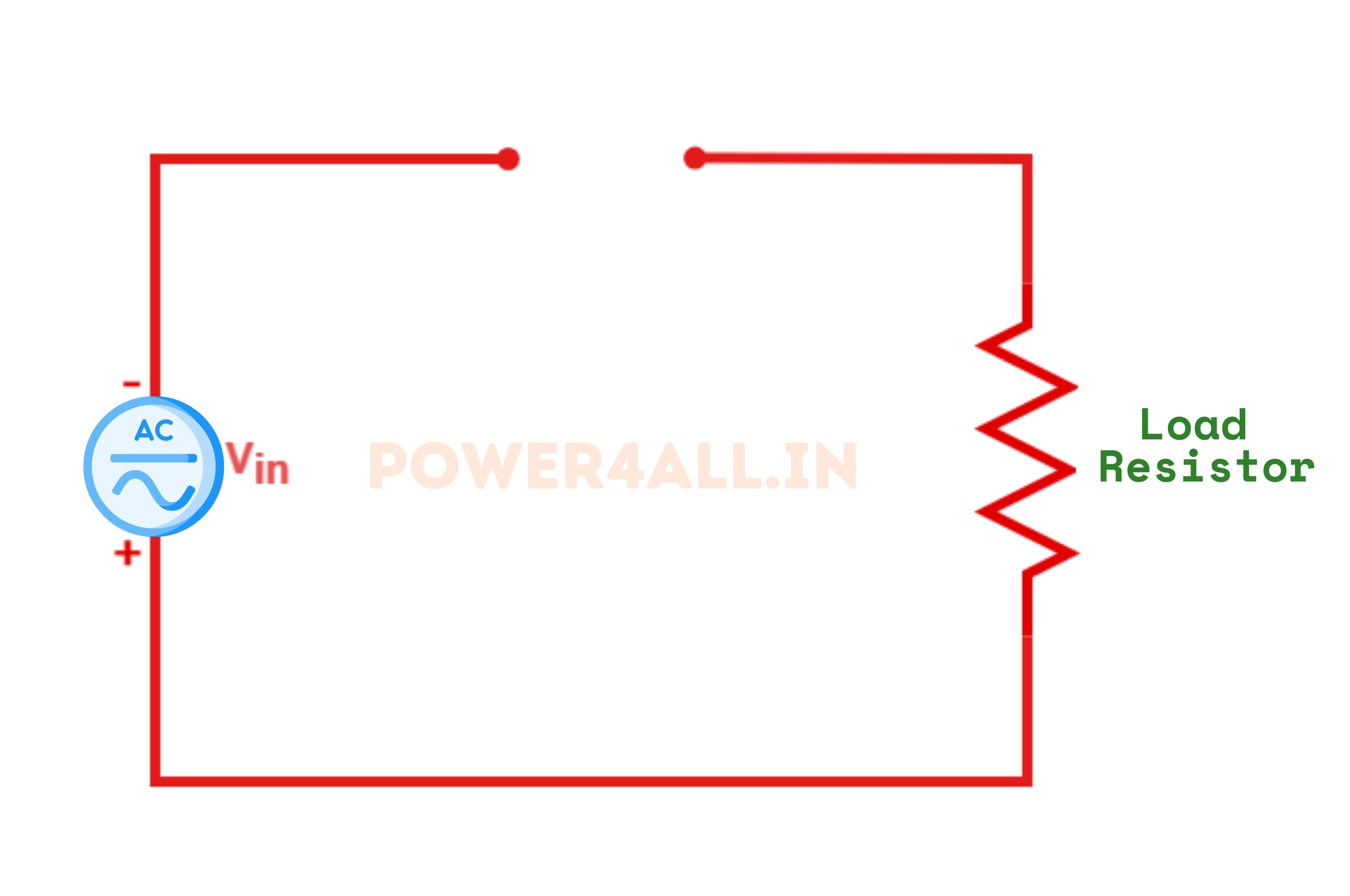
- During the negative half-cycle, the diode is reverse-biased and blocks current, so no output is delivered to the load.
- The output is a series of positive pulses (pulsating DC), with current flowing only during the positive half-cycles.
Half Wave Rectifier Waveforms
AC Input Waveform
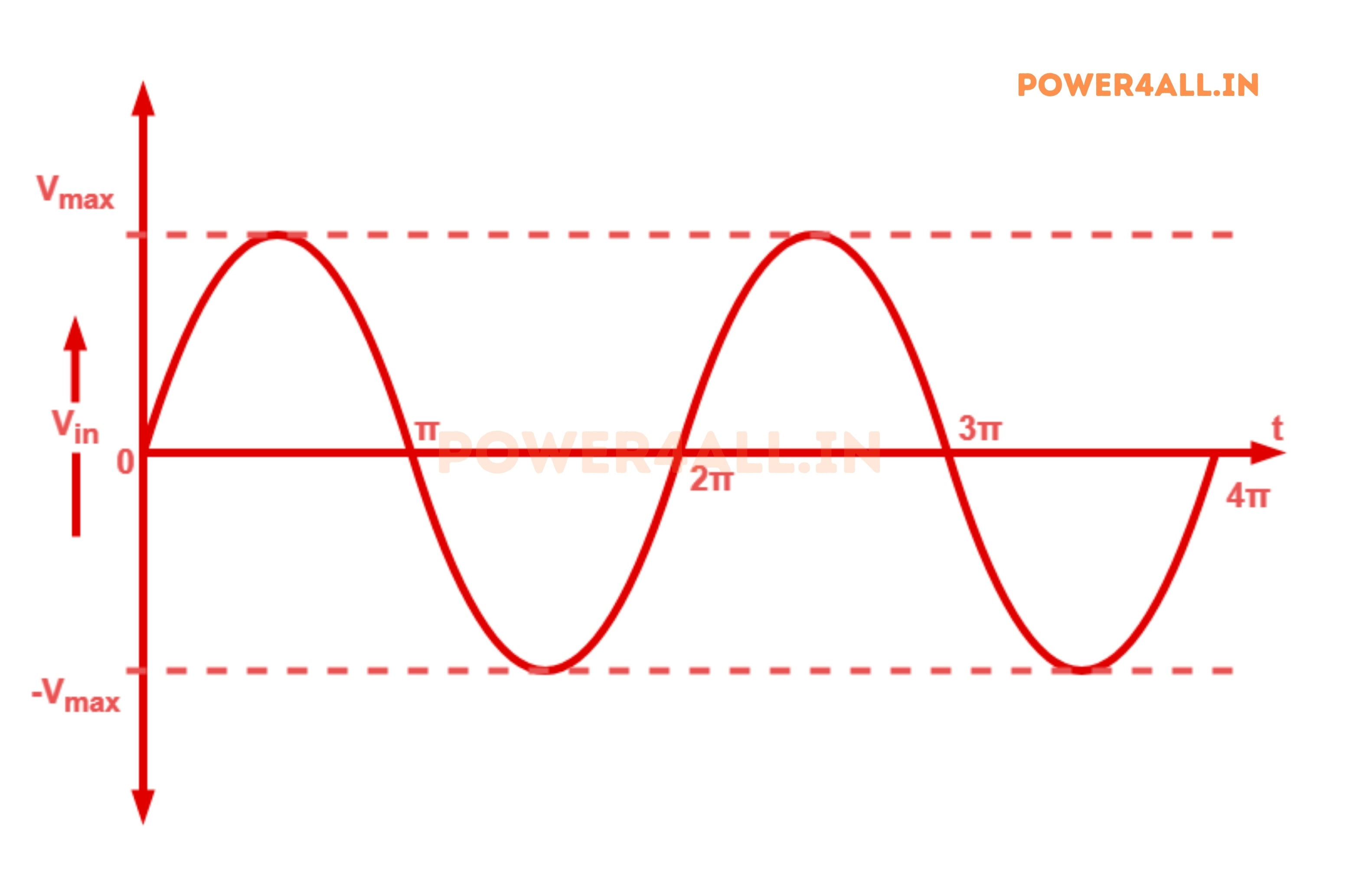
The diagram below depicts an AC input with a maximum voltage of Vmax. This AC waveform serves as the input for the half-wave rectifier, which subsequently converts it to DC.
DC Output Waveform
The diagram below presents the DC output waveform of a half-wave rectifier. During the positive half cycle of the input waveform, the diode permits the transmission of the input voltage, resulting in a visible positive half cycle in the output waveform. Conversely, during the negative half cycle of the input waveform, the diode obstructs the transmission of the voltage, leading to the absence of the negative half cycle in the output waveform and yielding an output voltage of zero. This process iterates, facilitating the conversion of the AC input to a pulsating DC output.
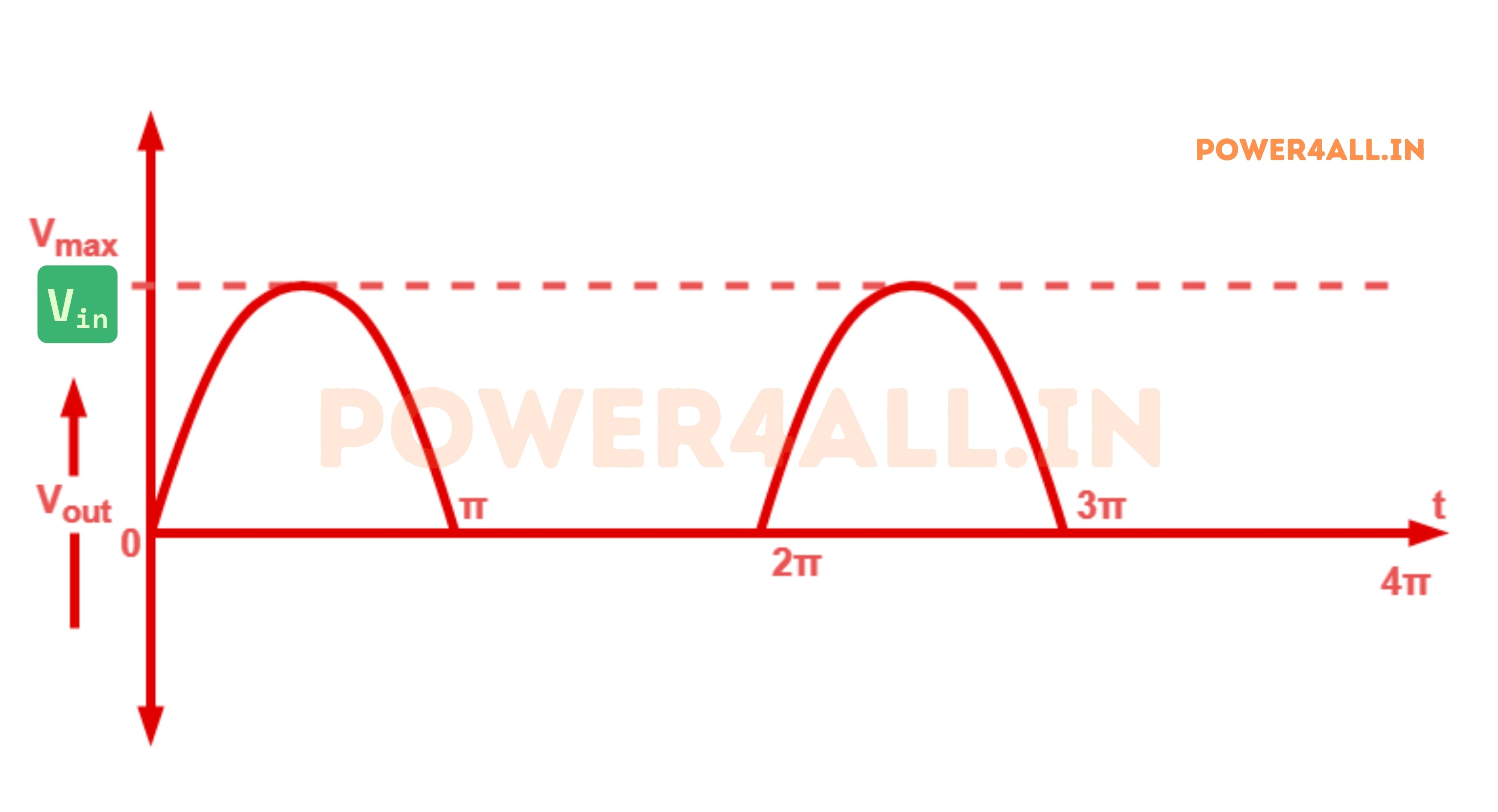
- AC Input: Sine wave with both positive and negative halves.
- Rectified Output: Only the positive half-cycles appear across the load; negative half-cycles are blocked.
- The output is not pure DC, but has significant ripple.
Half Wave Rectifier Capacitor Filter
To reduce the ripple and smooth the output, a capacitor filter is often added in parallel with the load. The capacitor charges during the conduction period and discharges slowly through the load when the diode is off, providing a more constant DC output. However, the filtering is not perfect, and some ripple remains, especially under heavy load.
Half Wave Rectifier Formula
| Parameter | Formula | Description |
|---|---|---|
| Average Output Voltage (VDC) | Vm / π | Mean value of the output voltage per cycle |
| RMS Output Voltage (VRMS) | Vm / 2 | Root mean square value of the output |
| Ripple Factor (γ) | 1.21 | Indicates the amount of AC content in the output |
| Peak Inverse Voltage (PIV) | Vm | Maximum voltage diode must withstand in reverse bias |
| Efficiency (η) | 40.6% | Ratio of DC output power to AC input power |
*Where Vm is the peak value of the input AC voltage.
Ripple Factor of Half Wave Rectifier
The ripple factor (γ) is the ratio of the RMS value of the AC component to the DC component in the output. For a half wave rectifier, γ = 1.21, indicating a high ripple content.
Efficiency of Halfwave Rectifier
The maximum efficiency of a half wave rectifier is 40.6%, meaning only about 40% of the input AC power is converted to DC output.
RMS value of Half Wave Rectifier
The RMS value of the output voltage is Vm/2, where Vm is the peak input voltage.
Form factor of a Halfwave Rectifier
The form factor is the ratio of RMS value to average value, which is 1.57 for a half wave rectifier.
Applications of Half Wave Rectifier
- Battery chargers for low current devices
- Signal demodulation circuits
- Basic DC power supplies
- Educational experiments and lab demonstrations
- Power supplies for specific low-power electronic equipment
Disadvantages of Half Wave Rectifier
- High ripple in output (not smooth DC)
- Low efficiency (only half the AC cycle is used)
- Not suitable for high-power or industrial applications
- Poor transformer utilization factor