Single Phase Half Wave Control Rectifier
A basic AC to DC converter using a single SCR, ideal for teaching phase control and variable DC output in low-power applications.
- What is a Controlled Rectifier?
- single-phase half-wave controlled rectifier
- Circuit Diagram Single Phase Half Wave Control Rectifier
- Working of Single-Phase Half Wave Controlled Rectifier
- Waveform of Half Wave Controlled Rectifier
- Calculation of Average and RMS Load Output Voltage
- Advantages
- Disadvantages
- Frequently Asked Questions – FAQs
- Related Topics
What is a Controlled Rectifier?
A controlled rectifier is an electronic circuit that converts AC (alternating current) to DC (direct current), but with the added benefit of being able to adjust the output voltage as needed. Unlike an uncontrolled rectifier, which always gives a fixed DC output, a controlled rectifier uses special components like thyristors (also called SCRs) that act as electronic switches. These switches can be turned on at different points in the AC cycle by sending a small control signal to their gate terminal. By changing the moment when the thyristor is triggered, you can control how much of the AC waveform is allowed through, which lets you adjust the average DC output voltage.
One of the advantages of using thyristors in controlled rectifiers is that they turn off automatically when the AC current naturally drops to zero, so there’s no need for extra circuits to switch them off. This makes controlled rectifiers simple and efficient for applications where you need to vary the DC output, such as controlling the speed of DC motors, dimming lights, or charging batteries. By selecting the right firing angle for the thyristor, you can easily change the power delivered to the load.
block diagram of controlled rectifer system
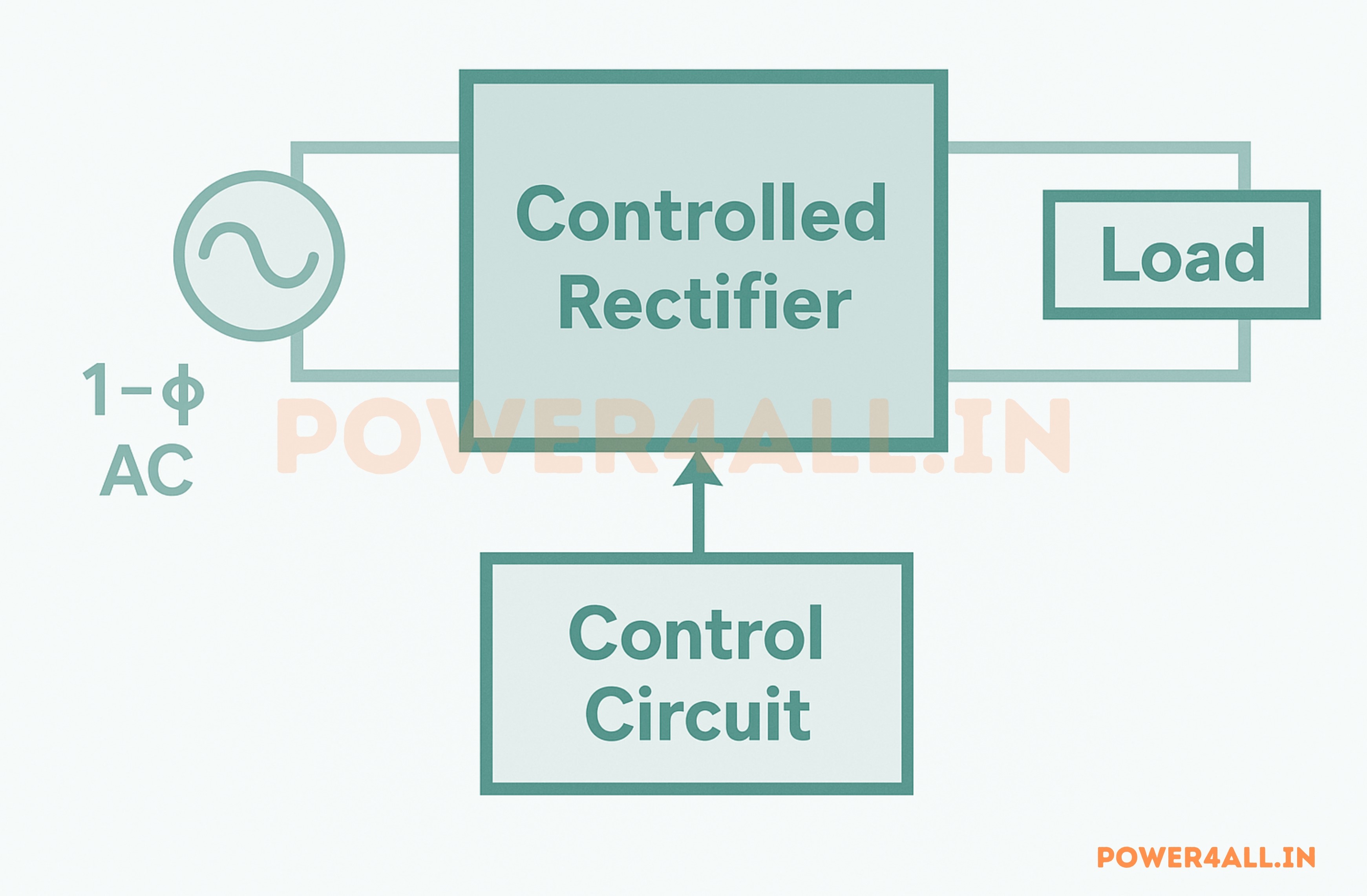
single-phase half-wave controlled rectifier
A single-phase half-wave controlled rectifier uses a thyristor (SCR), an AC power source, and a load that can be resistive, inductive, or both. The main feature of this system is that the SCR starts conducting only when it receives a signal at a specific firing angle. T his allows us to control when current flows through the load. By changing this firing angle, we can adjust the average DC output voltage and control the power going to the load. The efficiency and output depend on the type of load connected.
Real-life example:
A common use of a single-phase half-wave controlled rectifier is in light dimmers or fan speed controllers. For instance, in a ceiling fan regulator, the SCR is triggered at different points in the AC cycle to adjust how much power reaches the fan, allowing you to control its speed smoothly and efficiently.
Full-wave rectification is achieved through the utilization of a diode bridge, which consists of a combination of diodes. Each diode allows the flow of current in one direction and prevents it in the opposite direction. This fundamental principle is leveraged in the construction of various rectifier circuits.
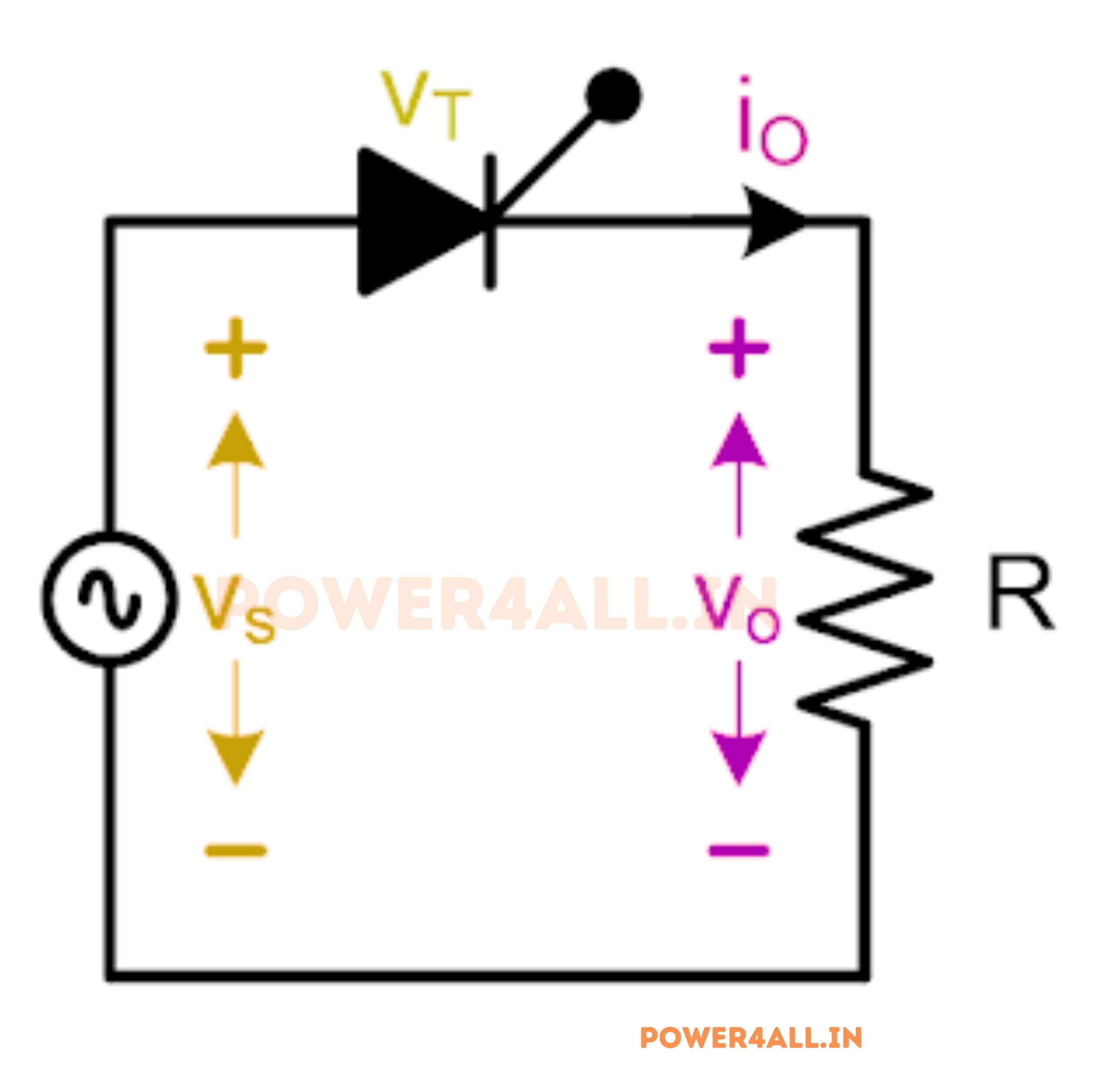
Circuit Diagram Single Phase Half Wave Control Rectifier
The circuit diagram depicting the single-phase half-wave controlled rectifier with a resistive load is illustrated in Figure below. This configuration comprises solely a Thyristor switch. An AC voltage source (vs) is connected at the input, while a resistive load (R) is connected at the output. The Thyristor is triggered to conduct upon the application of a firing pulse.
Working of Single-Phase Half Wave Controlled Rectifier
The single-phase half wave controlled rectifier with resistive load operates in two modes.
- Mode-I: Thyristor is OFF (0 to α and π to 2π)
- Mode-II: Thyristor is ON (α to π)
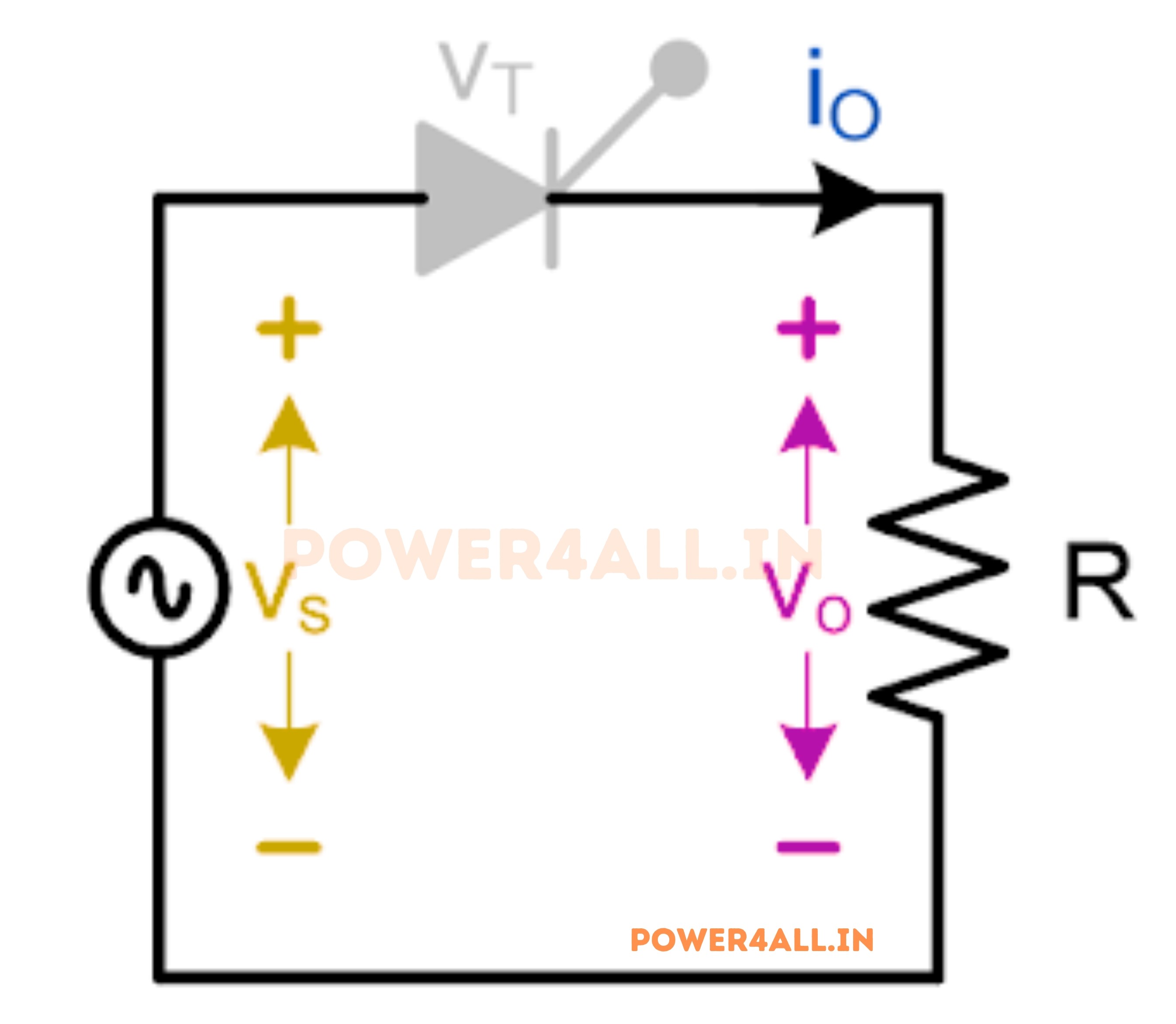
Mode-I: Thyristor is OFF (0 to α and π to 2π)
During mode-I the Thyristor is in the OFF state. The schematic representation of the single-phase half-wave controlled rectifier with a resistive load during mode-1 can be observed in Figure below. Given that the Thyristor is in the OFF state, the output current will register as zero, resulting in a corresponding output voltage of zero. Consequently, the entirety of the input will be apparent across the Thyristor.
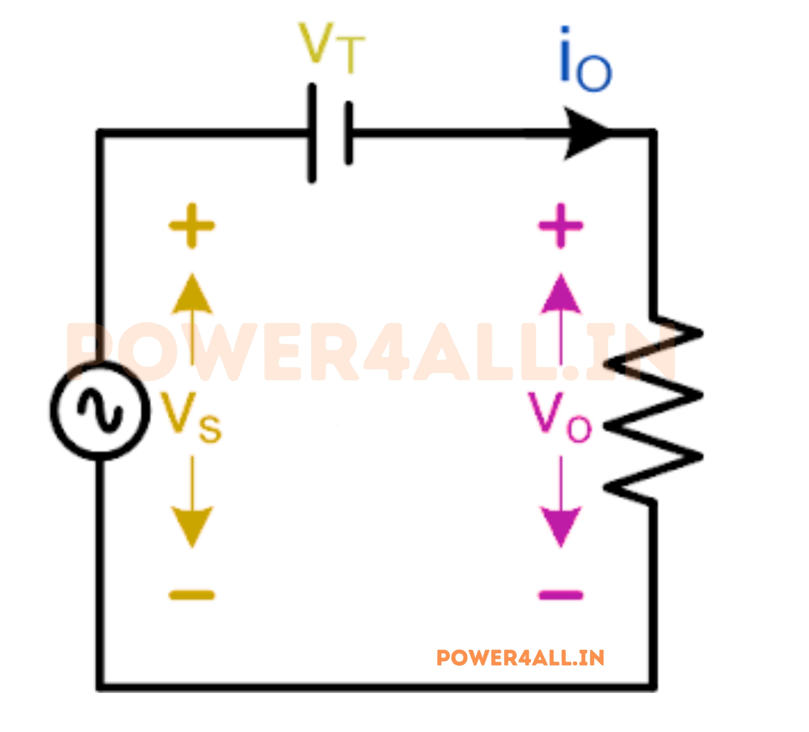
Mode-II: Thyristor is ON (α to π)
In this operational mode, the Thyristor is activated by a firing pulse. Figure below illustrates the equivalent circuit diagram of the single phase half wave controlled rectifier with a resistive load during mode-II. While the Thyristor is conducting, a nominal voltage drop (VT) occurs across it. For the purposes of this article, we are presuming a negligible voltage drop across the Thyristor. Consequently, the entire input voltage is expected to be present across the output.
Waveform of Half Wave Controlled Rectifier
The waveforms for the single-phase half-wave controlled rectifier with a resistive load are illustrated in Figure below. The AC input voltage source's waveform is denoted in red, while the firing signal waveform is represented in pink. Additionally, the waveform of the voltage across the resistive load is depicted in blue, the current through the resistive load in green, and the voltage across the thyristor in orange.
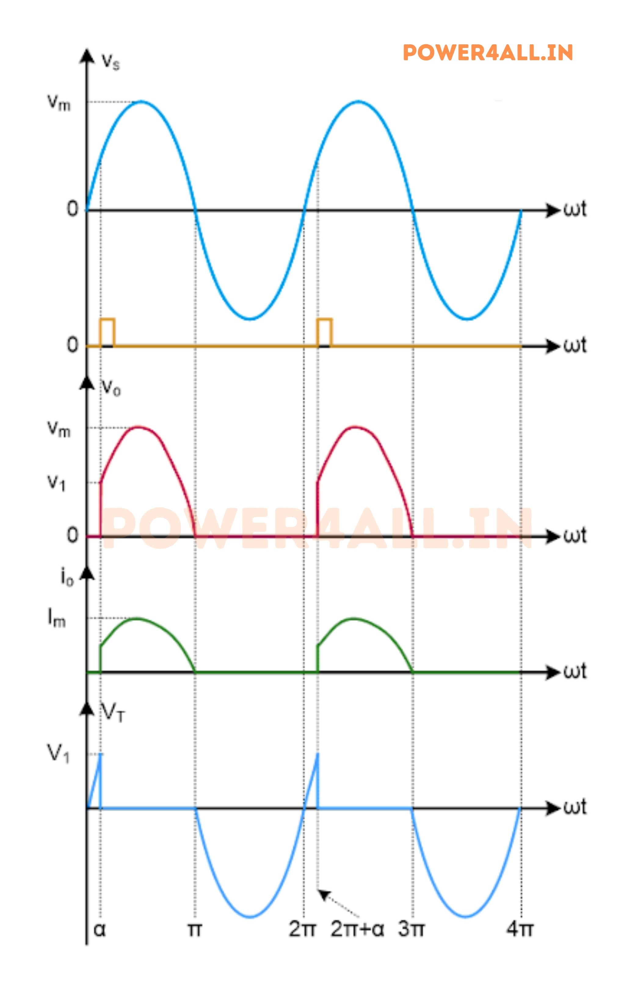
Thyristor T is forward biased for the positive half cycle of supply voltage. The load output voltage is zero till SCR is fired. Once SCR is fired at an angle of α, SCR starts conducting. But as soon as the supply voltage becomes zero at ωt = π, the load current will become zero and after ωt = π, SCR is reversed biased. Thus thyristor T will turn off at ωt = π and will remain in OFF condition till it is fired again at ωt = (2π+α).
Therefore, the load output voltage and current for one complete cycle of input supply voltage may be written as
- Vo = VmSinωt for α≤ωt≤ π
- Io = VmSinωt / R for α≤ωt≤ π
Calculation of Average and RMS Load Output Voltage
Below are the detailed steps to calculate the average and RMS value of the load output voltage for a Single Phase Half Wave Controlled Rectifier.
Average Value of Load Output Voltage
$$\text{Average Value of Load Output Voltage}$$
$$= \frac{1}{2\pi} \int_{0}^{2\pi} V_m \sin(\omega t)\, d(\omega t)$$
$$= \frac{1}{2\pi} \left[ \int_{0}^{\alpha} V_m \sin(\omega t)\, d(\omega t) + \int_{\alpha}^{\pi} V_m \sin(\omega t)\, d(\omega t) + \int_{\pi}^{2\pi} V_m \sin(\omega t)\, d(\omega t) \right]$$
Since the value of load output voltage is zero from \(0 \leq \omega t < \alpha\) and \(\pi < \omega t < 2\pi\),
$$= \frac{1}{2\pi} \int_{\alpha}^{\pi} V_m \sin(\omega t)\, d(\omega t)$$
$$= \frac{V_m}{2\pi} \int_{\alpha}^{\pi} \sin(\omega t)\, d(\omega t)$$
$$= \frac{V_m}{2\pi} \left[ -\cos(\omega t) \right]_{\alpha}^{\pi}$$
$$= \frac{V_m}{2\pi} [1 + \cos\alpha]$$
$$\boxed{ \text{Average Value of Load Output Voltage} = \frac{V_m}{2\pi} [1 + \cos\alpha] }$$
RMS Value of Load Output Voltage
$$\text{RMS Value} = \sqrt{ \frac{1}{T} \int_{0}^{T} [f(x)]^2 dx }$$
$$\text{RMS Value of Load Output Voltage}$$
$$= \sqrt{ \frac{1}{2\pi} \int_{0}^{2\pi} [V_m \sin(\omega t)]^2 d(\omega t) }$$
$$= \sqrt{ \frac{V_m^2}{2\pi} \int_{0}^{2\pi} \sin^2(\omega t) d(\omega t) }$$
$$= \sqrt{ \frac{V_m^2}{4\pi} \int_{0}^{2\pi} [1 - \cos 2\omega t] d(\omega t) }$$
Since the value of load output voltage is zero from \(0 \leq \omega t < \alpha\) and \(\pi < \omega t < 2\pi\),
$$= \sqrt{ \frac{V_m^2}{4\pi} \int_{\alpha}^{\pi} [1 - \cos 2\omega t] d(\omega t) }$$
$$= \frac{V_m}{2\sqrt{\pi}} \sqrt{ (\pi - \alpha) + \frac{1}{2} \sin 2\alpha }$$
$$\boxed{ \text{RMS Value} = \frac{V_m}{2\sqrt{\pi}} \sqrt{ (\pi - \alpha) + \frac{1}{2} \sin 2\alpha } }$$
*Where \( V_m \) is the peak value of the input AC voltage and \( \alpha \) is the firing angle of the SCR.
Advantages
- Simplicity:.The circuit design is straightforward, involving fewer components compared to other types of rectifiers.
- Cost-Effective:Fewer components result in lower manufacturing costs, making it an economical choice for basic applications.
- Controlled Output:The thyristor allows control over the output voltage by adjusting the firing angle, which provides flexibility in regulating the output.
- Efficiency at Low Power Levels:It can be efficient in low-power applications, reducing energy loss and heat generation.
- The power loss in these systems is minimal due to the efficient utilization of voltage signals in the rectification process.
- The output voltage of a center-tapped full-wave rectifier exhibits reduced ripple compared to that of a half-wave rectifier.
Disadvantages
- Low Efficiency:The rectifier only utilizes one half-cycle of the AC input, leading to lower efficiency compared to full-wave rectifiers.
- High Ripple Factor:The output contains significant ripple (AC components), requiring additional filtering to produce a smoother DC output.
- Unidirectional Conduction:The current flows in only one direction, which can be a limitation in some applications.
- DC Component in the Transformer: The unidirectional current can lead to a DC component in the transformer, which can cause saturation and reduce its efficiency and lifespan.
- Poor Transformer Utilization:In applications where a transformer is used, the transformer is not utilized to its full capacity, leading to potential inefficiencies.
FAQ: Single Phase Half-Wave Controlled Rectifier
$$ V_{DC} = \frac{V_m}{2\pi} [1 + \cos\alpha] $$
where \( V_m \) is the peak AC voltage and \( \alpha \) is the firing angle.
$$ V_{RMS} = \frac{V_m}{2\sqrt{\pi}} \sqrt{(\pi-\alpha) + \frac{1}{2} \sin 2\alpha} $$
where \( V_m \) is the peak AC voltage and \( \alpha \) is the firing angle.