Cuk Converter
The primary function of a Cuk converter is to step up or step down voltage from a lower level to a higher level.
- Introduction
- DC-DC CUK CONVERTER
- Working Principle of Cuk Converter
- Mode 1: When the switch S is ON
- Mode 2: When the switch S is OFF
- Mode 3: When the switch S is ON
- Mode 4: When the switch S is OFF
- Waveform of Cuk Converter
- Advantages of Cuk Converter
- Disadvantages of Cuk Converter
- Applications of Cuk Converter
- Conclusion
- Frequently Asked Questions About Cuk Converter – FAQs
- Related Topics
Introduction
When it comes to DC-DC power conversion, the Ćuk converter stands out as a unique and versatile solution. Named after its inventor, Slobodan Ćuk, this converter offers something special - the ability to both step up and step down voltage while inverting the polarity. Unlike simpler converters, the Ćuk uses capacitive energy transfer, giving it advantages in noise reduction and output quality that engineers have come to appreciate.
What makes the Ćuk converter different from its cousins in the converter family is how it handles energy. Instead of relying primarily on an inductor for energy storage, it uses a capacitor as the main energy transfer element. This seemingly small design choice leads to continuous current flow at both input and output, reducing electromagnetic interference and stress on components. For sensitive electronics or applications where noise matters, this characteristic is a game-changer.
The Ćuk topology might look more complex at first glance, with its extra components compared to buck or boost converters, but this complexity brings rewards. The smoother current waveforms mean smaller filter components, and the inherent voltage inversion opens up possibilities in applications requiring negative voltage rails. From audio equipment to industrial control systems, the Ćuk converter has found its place wherever clean, efficient power conversion matters. While it might not be as widely known as some other converter types, engineers who discover its benefits often find it's exactly what they needed.
DC-DC CUK CONVERTER
The Cuk converter, named after its inventor Slobodan Cuk, is a power electronic converter that operates on the principles of DC-DC conversion. It was developed to mitigate the limitations observed in the buck-boost converter. Before delving into the operational principles of the Cuk converter, it is imperative to acquire a comprehensive understanding of other DC-DC converters, as this will facilitate the study of the Cuk converter.
The Cuk Converter is also known as the optimum topology converter and spelled as cuk and pronounced as chook.
The DC-DC converter operates with a fixed input and regulated output, achieved through a buck converter for voltage reduction and a boost converter for voltage increase. An alternative topology involves the use of a Buck-Boost converter, providing adjustable voltage step-up or step-down capabilities. This converter uniquely yields output with an inverted polarity. The Cuk converter operates on a similar principle to the Buck-Boost converter, but with an output polarity reversal. Common DC-DC converters, such as the buck, boost, and buck-boost, consist of one capacitor, one inductor, one diode, and one semiconductor switch. Contrastingly, the Cuk converter architecture comprises two inductors, two capacitors, a diode, and a semiconductor switch, resulting in reduced voltage ripple on both input and output sides. A detailed exploration of the Cuk converter's topology will be presented in this section.
Working Principle of Cuk Converter
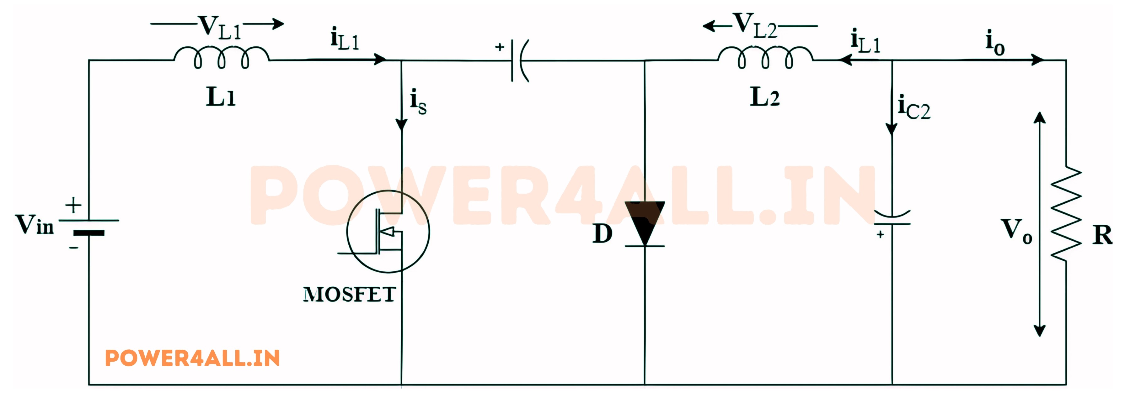
The Cuk converter, depicted in the figure, comprises six components: L1, L2, C1, C2, diode D, and switch S. Prior to examining its operational principles, it is pertinent to establish the ideal conditions for the components, namely that L1, L2, C1, and C2 are devoid of charge. The operation of the Cuk converter is simplified into 4 modes for analysis.
The circuit diagram for a typical Cuk converter is shown in the figure below.
There are four modes of operation of the Cuk Converter.
Mode 1: When the switch S is ON
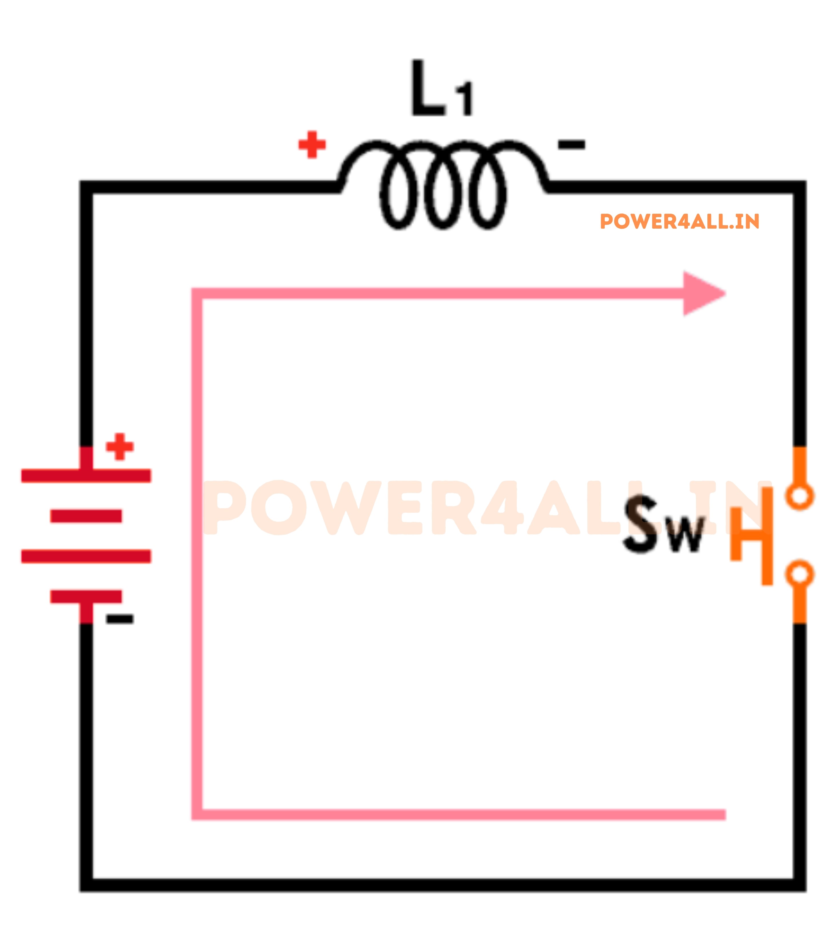
In the above Figure, when the switch is turned on, the source charges the inductor, resulting in a flow of current from L1 to the switch and back to the source.
The inductor L1 becomes charged and acts as a storage element with polarity from positive to negative. Technically, there will be a small amount of stored voltage in C1, but there is no current flow to the load.
Mode II: Switch S is OFF

When the switch is turned OFF, as depicted in above figure, the inductor L1 releases the stored energy by reversing its polarity. Additionally, current flows from the source to the inductor L1 as the energy dissipates. This current flow occurs because the current from inductor L1 is not purely DC.
When the switch is turned off, the current will flow from the power source through inductor L1, then to capacitor C1, and from there through the diode back to the power source. During this process, capacitor C1 will also store the voltage. The load will receive voltage in this state while the switch is off.
Mode III: Switch S is ON
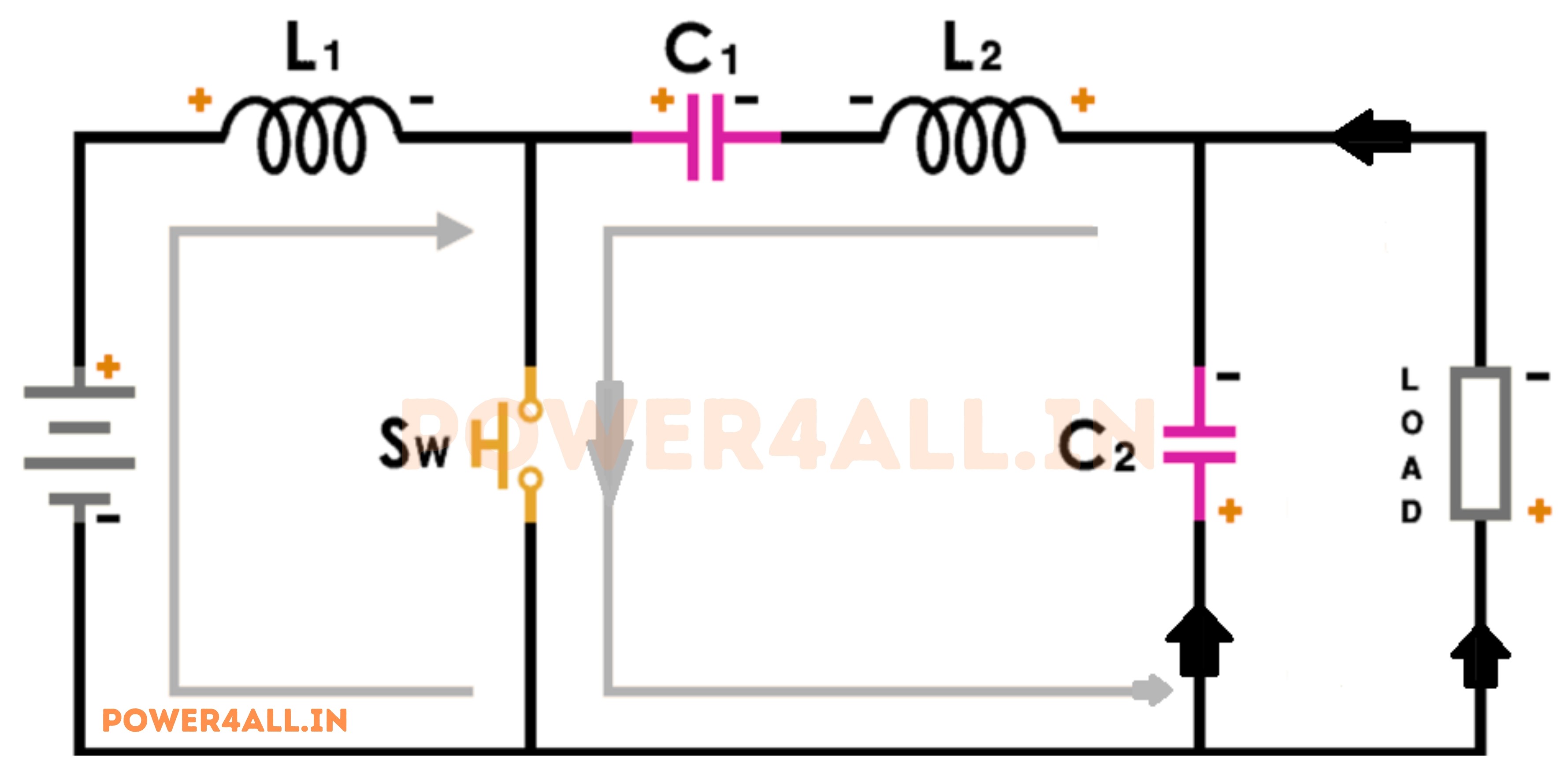
When the switch is turned ON, according to the illustration in above figure, the inductor L1 undergoes charging in Mode-I, resulting in the flow of current from the source to inductor L1, then to capacitor C2 and the load. Simultaneously, the previously charged capacitor C1 dissipates its stored energy to the load.
The voltage retained in capacitor C1 serves as a voltage source, facilitating the flow of current from capacitor C1 to C2 and the load. Furthermore, this process involves the charging of inductor L2, as diode D becomes reverse-biased.
Mode IV: Switch S is OFF
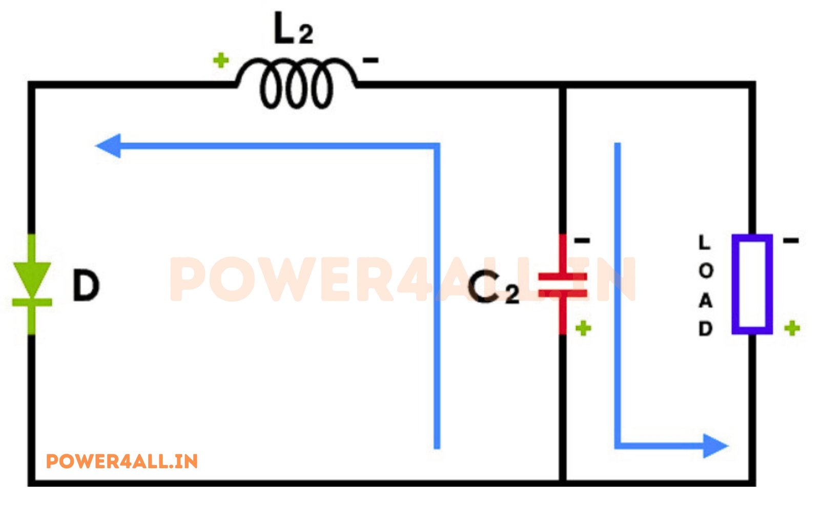
When the switch is turned off, as illustrated in above figure, the system enters a state where capacitor C1 discharges its stored energy. Additionally, inductor L2, previously charged in the preceding state, also releases its energy to the load. This results in both capacitor C1 and L2 dissipating their stored energy to the load.
The diode becomes forward-biased, causing capacitor C2 and L2 to release their stored energy, leading to a reversal of the output voltage.
This ON/OFF mechanism causes the output voltage to have a reversed polarity in comparison to the input side voltage.
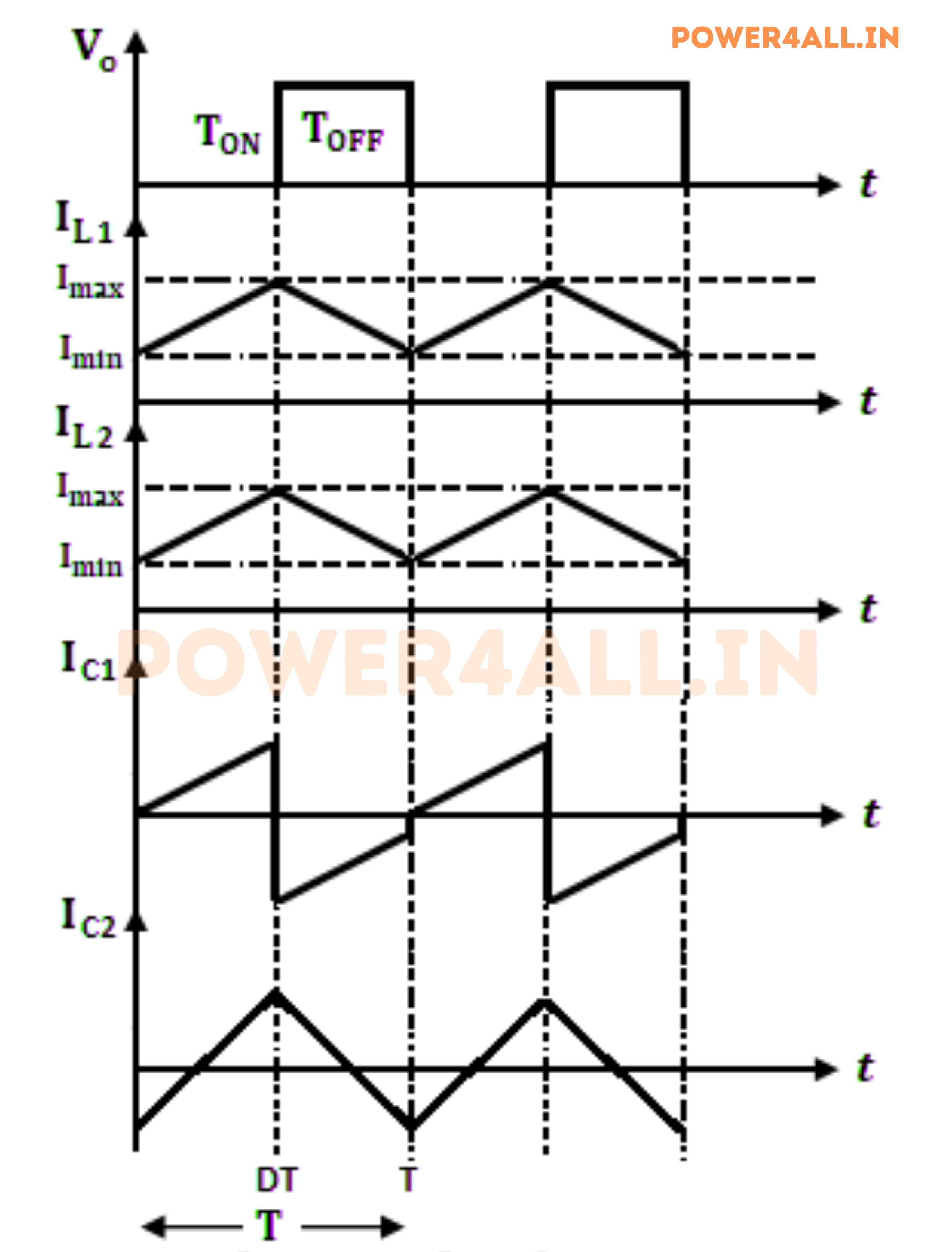
Waveform of CUK Converter
The waveform of a CUK converter is characterized by its distinct voltage and current profiles during the two operational modes. The following figure illustrates the voltage and current waveforms associated with the CUK converter's operation.
Advantages of CUK Converter
The CUK converter offers several advantages, making it a popular choice in various applications:
- Even in the deactivated state, the transmission of energy to the load persists due to the uninterrupted flow of input and output current.
- The CUK converter architecture incorporates inductor L1 on the input side and inductor L2 on the output side, resulting in reduced input and output voltage ripple.
- This architecture affords the capability to adjust the output voltage both upwards and downwards. Specifically, when the duty ratio is less than 0.5, it functions as a step-down converter, and when the duty ratio exceeds 0.5, it operates as a step-up converter.
- By winding inductors L1 and L2 on a single-core wire, it is possible to reduce the overall component size. Additionally, this topology demonstrates a notably higher efficiency when compared to the buck-boost topology.
Disadvantages of CUK Converter
While CUK converters have many advantages, they also have some disadvantages:
- The CUK converter is more complex than other converters, such as buck or boost converters, due to the additional components involved.
- It requires careful design and control to ensure stable operation, especially in applications with varying load conditions.
- The presence of multiple inductors and capacitors can lead to increased size and cost compared to simpler converter topologies.
- Switching losses can be higher in CUK converters, especially at high frequencies, which may affect efficiency.
Applications of CUK Converter
CUK converters find applications in various fields, including:
- Power supplies for electronic devices, where voltage regulation is critical.
- Battery management systems, where the converter can step up or step down voltage as needed.
- Renewable energy systems, such as solar power, where voltage levels may vary.
- LED lighting systems, where constant current and voltage regulation are required.
- Industrial applications, including motor drives and control systems.
Conclusion
In conclusion, the CUK converter is a versatile and efficient DC-DC converter topology that offers both step-up and step-down voltage conversion with the added benefit of continuous current flow. Its unique design, which incorporates capacitive energy transfer, makes it suitable for applications where low noise and high efficiency are essential. While it may be more complex than other converter types, its advantages in voltage regulation and reduced ripple make it a valuable choice in various electronic systems.