Complete Transformer Mastery Guide
Master the fundamentals of transformers - from basic principles and electromagnetic induction to advanced applications in power systems and electronics
Complete Learning Path - Transformer Fundamentals to Applications
Navigate through comprehensive coverage of transformers from basic principles to advanced applications
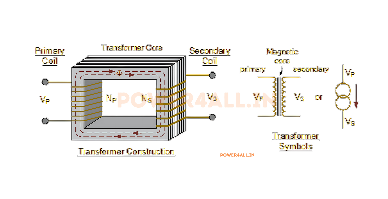
What is a Transformer?
A transformer is an electrical device that transfers electrical energy between two or more circuits through electromagnetic induction. Think of it as an electrical "gear system" that can increase (step up) or decrease (step down) voltage levels while maintaining power conservation, making it one of the most fundamental components in electrical power systems.
Vp/Vs = Np/Ns = Is/Ip
Primary to Secondary Voltage, Turns, and Current Ratio
Why Transformers are Essential
Transformers are the backbone of our electrical infrastructure. Without them, efficient power transmission over long distances would be impossible, and most electronic devices couldn't operate safely from wall outlets.
Voltage Transformation
Step voltage up for efficient long-distance transmission or step down for safe use in homes and devices.
Electrical Isolation
Provide galvanic isolation between circuits, enhancing safety and preventing ground loops.
Impedance Matching
Match impedances between different circuit sections for maximum power transfer efficiency.
Power Conservation
Transfer power with minimal losses while changing voltage and current levels according to circuit needs.
Transformer Symbol and Basic Principles
Circuit Symbols
- Iron Core: Two coils with parallel lines (core symbol)
- Air Core: Two coils without core lines
- Variable: Arrow through symbol
- Auto-transformer: Single coil with tap
- Current transformer: Special CT symbol
Key Parameters
- Turns Ratio (a): Np/Ns - determines voltage transformation
- Power Rating: Maximum power it can handle safely
- Frequency: Operating frequency (50Hz/60Hz for power)
- Efficiency: Percentage of input power delivered to output
- Regulation: Voltage change from no-load to full-load
Everyday Transformer Examples
- Phone charger: Step-down transformer converting 120V AC to 5V DC
- Microwave: Step-up transformer providing high voltage for magnetron
- Distribution transformer: 4160V to 240V/120V for neighborhood supply
- Current transformer: Measuring high currents safely in power meters
- Audio transformer: Matching microphone impedance to amplifier input
- Isolation transformer: Providing safety isolation in medical equipment
Did You Know?
The first transformer was invented in 1886 by William Stanley Jr. Modern power transformers can be 99.7% efficient and handle hundreds of megawatts of power. The largest power transformers weigh over 400 tons and cost millions of dollars!
Transformer Fundamentals: How They Work
Understanding transformer operation requires grasping the principles of electromagnetic induction, mutual inductance, and magnetic circuits. These concepts explain how transformers can transfer electrical energy between circuits without any physical connection.
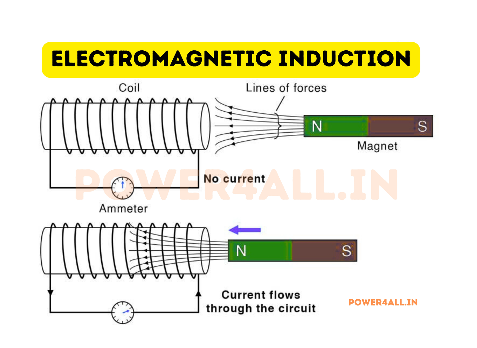
Faraday's Law of Electromagnetic Induction
The Physical Principle Behind Transformer Operation
Transformers work because of Faraday's fundamental discovery: a changing magnetic field induces an electric field (and therefore voltage) in nearby conductors. This is the physical principle that enables energy transfer without direct electrical connection.
The Step-by-Step Process
ε = -N × dΦ/dt
Induced EMF = Number of turns × Rate of flux change
Key Factors Affecting Induction
| Factor | Effect on Induced Voltage | Why This Happens | Practical Implication |
|---|---|---|---|
| Number of Turns | More turns = Higher voltage | Each turn adds to total induced EMF | Voltage ratio equals turns ratio |
| Rate of Flux Change | Faster change = Higher voltage | Derivative relationship in Faraday's law | Higher frequency increases voltage |
| Core Material | Better core = Higher efficiency | High permeability concentrates flux | Iron cores much better than air |
| Core Geometry | Closed path = Better coupling | Minimizes flux leakage | Toroidal cores most efficient |
Mutual Inductance and Coupling
What is Mutual Inductance?
Mutual inductance (M) quantifies how effectively magnetic flux from one coil links with another coil. Perfect coupling means all flux from primary links with secondary, while poor coupling means much flux is lost.
M = k√(L₁L₂)
M = mutual inductance, k = coupling coefficient
Coupling Coefficient Values
- k = 1.0: Perfect coupling (theoretical)
- k = 0.95-0.99: Excellent (iron core transformers)
- k = 0.8-0.95: Good (ferrite core transformers)
- k = 0.1-0.8: Fair (air core, loose coupling)
- k < 0.1: Poor coupling (significant losses)
Ideal vs Real Transformer Behavior
Understanding Practical Limitations and Losses
Ideal Transformer Assumptions
Perfect Conditions
- 100% coupling: All flux links both windings
- Zero resistance: No I²R losses in windings
- Infinite permeability: Core requires no magnetizing current
- No flux leakage: Perfect magnetic circuit
- No core losses: No hysteresis or eddy current losses
Real-World Effects
- Winding resistance: I²R losses cause heating and voltage drop
- Leakage inductance: Flux that doesn't link both windings
- Magnetizing current: Current needed to establish core flux
- Core losses: Hysteresis and eddy current losses
- Saturation: Core magnetic saturation at high flux levels
Transformer Equivalent Circuit
Components of Real Transformer Model
- R₁, R₂: Primary and secondary winding resistances
- X₁, X₂: Primary and secondary leakage reactances
- Xₘ: Magnetizing reactance (infinite in ideal case)
- Rᶜ: Core loss resistance (infinite in ideal case)
- a: Ideal transformer with turns ratio
| Parameter | Ideal Value | Typical Real Value | Effect on Performance |
|---|---|---|---|
| Efficiency | 100% | 95-99.7% | Power losses as heat |
| Voltage regulation | 0% | 1-5% | Output voltage varies with load |
| No-load current | 0 | 2-10% of rated | Magnetizing and core loss current |
| Frequency response | Perfect | Limited bandwidth | Leakage inductance limits high frequency |
Types of Transformers: Complete Classification
Transformers come in many varieties, each designed for specific applications and operating conditions. Understanding the different types helps in selecting the right transformer for power transmission, electronics, measurement, or specialized applications.

Power Transformers
Distribution Transformers
Step down high voltage for consumer use
Typical Voltage Levels
- Primary: 4.16kV, 12.47kV, 25kV, 35kV
- Secondary: 120V, 240V, 480V
- Power ratings: 10kVA to 5000kVA
- Installation: Pole-mounted or pad-mounted
- Cooling: Oil-filled or dry-type
Key Features
- High efficiency (98-99%)
- Designed for continuous operation
- Multiple secondary taps
- Protective devices integrated
- Weather-resistant enclosures
Common Applications
- Residential neighborhood power supply
- Commercial building distribution
- Industrial plant power distribution
- Street lighting systems
- Agricultural power supply
Power Station Transformers
Step up generator voltage for transmission
Massive Scale Operations
- Generator side: 11kV, 22kV, 25kV
- Transmission side: 138kV, 230kV, 500kV, 765kV
- Power ratings: 100MVA to 1000MVA+
- Weight: 100 to 400+ tons
- Cooling: Forced oil and air circulation
Advanced Features
- On-load tap changers
- Dissolved gas analysis monitoring
- Temperature monitoring systems
- Buchholz relay protection
- Surge arresters
Critical Applications
- Nuclear power plant step-up
- Coal-fired power station transformers
- Hydroelectric generator step-up
- Wind farm collection transformers
- Solar farm inverter transformers
Isolation Transformers
Safety isolation without voltage change
Safety and Protection
- Turns ratio: 1:1 (no voltage change)
- Primary purpose: Galvanic isolation
- Insulation: High voltage breakdown rating
- Grounding: Isolated secondary ground system
- Noise reduction: Eliminates common-mode noise
Critical Safety Applications
- Medical equipment power supply
- Computer and server power
- Test equipment isolation
- Audio system ground loop elimination
- Sensitive instrumentation power
Measurement and Control Transformers
Instrument Transformers for Measurement and Protection
Current Transformers (CTs)
Current transformers step down high currents to safe, measurable levels (typically 5A or 1A secondary) while maintaining proportional relationship to primary current.
Metering CTs
- Accuracy class: 0.1, 0.2, 0.5 for revenue metering
- Burden: Low impedance for accurate measurement
- Saturation: Designed to avoid saturation at rated current
- Applications: kWh meters, power quality monitoring
- Safety: Secondary must never be open-circuited
Protection CTs
- Accuracy class: 5P, 10P for protective relaying
- High fault current: Must operate accurately during faults
- Saturation characteristics: Designed for fault current levels
- Applications: Overcurrent relays, differential protection
- Multiple cores: Separate cores for metering and protection
Voltage Transformers (VTs/PTs)
| Type | Primary Voltage | Secondary Voltage | Accuracy Class | Application |
|---|---|---|---|---|
| Low voltage VT | 120V - 600V | 120V | 0.3, 0.6 | Panel meters, protection |
| Medium voltage VT | 2.4kV - 35kV | 120V | 0.3, 0.6, 1.2 | Switchgear metering |
| High voltage VT | 46kV - 800kV | 120V | 0.3, 0.6 | Transmission protection |
| Capacitive VT (CVT) | 115kV - 800kV | 120V | 0.3, 0.6 | EHV transmission systems |
Special Purpose Transformers
Audio Transformers
Optimized for audio frequency range
Audio-Specific Features
- Frequency response: 20Hz to 20kHz flat response
- Low distortion: Minimal harmonic distortion
- Impedance matching: Match microphones to amplifiers
- Isolation: Break ground loops in audio systems
- Shielding: Magnetic shielding from interference
Audio Applications
- Microphone input transformers
- Audio line isolation transformers
- Speaker matching transformers
- Tube amplifier output transformers
- Professional audio balancing
High-Frequency Transformers
Switching power supply and RF applications
High-Frequency Design
- Ferrite cores: Low losses at high frequencies
- Litz wire: Reduces skin effect losses
- Minimal turns: Reduces leakage inductance
- Tight coupling: Maximizes efficiency
- Thermal management: High power density challenges
Modern Applications
- Switch-mode power supplies
- DC-DC converters
- Flyback transformers
- RF impedance matching
- Wireless power transfer
Auto-transformers
Single winding with multiple taps
Auto-transformer Advantages
- Higher efficiency: Only part of power is transformed
- Smaller size: Less copper and iron required
- Lower cost: Economical for small voltage changes
- Better regulation: Lower impedance
- Continuous adjustment: Variable ratio possible
Safety Note
Auto-transformers provide no electrical isolation between primary and secondary. Use only where isolation is not required.
Transformer Construction & Materials
The performance, efficiency, and reliability of a transformer depend heavily on its construction materials and design. Understanding core materials, winding techniques, and insulation systems is crucial for selecting and applying transformers effectively.

Core Materials and Design
Silicon Steel Laminations
Standard material for power transformers
Material Properties
- Composition: Iron with 3-4% silicon content
- Grain orientation: Oriented or non-oriented steel
- Thickness: 0.23mm to 0.35mm laminations
- Insulation: Oxide coating between laminations
- Permeability: High magnetic permeability
Advantages
- Low core losses (hysteresis and eddy current)
- High saturation flux density
- Excellent mechanical properties
- Cost-effective for large transformers
- Proven reliability over decades
Core Construction Types
- E-I laminations: Easy to wind, moderate efficiency
- E-E laminations: Better magnetic circuit, less leakage
- C-cores: Reduced air gaps, higher efficiency
- Toroidal: Maximum efficiency, minimal stray field
Ferrite Cores
High-frequency and switch-mode applications
Ferrite Characteristics
- Material: Ceramic magnetic material (iron oxides)
- Frequency range: 1kHz to several MHz
- Core shapes: E, EE, ETD, RM, toroidal
- Saturation: Lower than silicon steel but adequate
- Temperature stability: Good up to 100-200°C
Applications
- Switch-mode power supply transformers
- DC-DC converter transformers
- High-frequency inductors
- EMI suppression components
- Wireless power transfer coils
| Ferrite Grade | Frequency Range | Permeability | Application |
|---|---|---|---|
| 3C90 | 25kHz - 200kHz | 2300 | Power transformers |
| 3C94 | 50kHz - 500kHz | 2800 | SMPS transformers |
| 3F3 | 100kHz - 1MHz | 2000 | High-frequency transformers |
Air Core and Other Materials
Specialized applications and materials
Air Core Transformers
- No magnetic core: Windings on non-magnetic former
- Linear operation: No saturation effects
- High frequency: No core losses at RF frequencies
- Low coupling: Typically 0.1 to 0.8 coupling coefficient
- Applications: RF transformers, Tesla coils
Advanced Core Materials
- Amorphous steel: Very low core losses
- Nanocrystalline: Ultra-low losses, high frequency
- Powder cores: Distributed air gap, high current
- Supermalloy: Extremely high permeability
Winding Design and Conductor Materials
Conductor Selection and Winding Techniques
Conductor Materials
| Material | Conductivity | Advantages | Applications |
|---|---|---|---|
| Copper | 100% (standard) | Excellent conductivity, ductile, solders well | Most transformer windings |
| Aluminum | 61% | Lightweight, lower cost, good for large transformers | Large power transformers |
| Silver | 106% | Best conductivity, oxidation resistant | High-end audio, RF applications |
| Litz wire | Variable | Reduces skin effect at high frequency | High-frequency transformers |
Winding Configurations
Concentric Windings
Primary and secondary windings placed concentrically around the core. Good coupling, easy to manufacture, most common configuration.
Interleaved Windings
Primary and secondary sections alternated along the core. Better coupling, reduced leakage inductance, more complex construction.
Pancake Windings
Flat, disc-shaped coils stacked and interconnected. Excellent for high-voltage applications, good cooling, precise control.
Helical Windings
Continuous helical winding with crossover connections. Used in high-current applications, good mechanical strength.
Insulation Systems
Electrical Insulation and Thermal Management
Insulation Classes and Temperature Ratings
| Class | Temperature Limit | Typical Materials | Applications |
|---|---|---|---|
| Class A | 105°C | Paper, cotton, natural resins | Small power transformers |
| Class E | 120°C | Synthetic resins, enamel films | General purpose transformers |
| Class B | 130°C | Mica, fiberglass, polyester | Medium power transformers |
| Class F | 155°C | High-grade synthetic materials | Modern power transformers |
| Class H | 180°C | Silicone resins, polyimide | High-temperature applications |
Insulation System Components
Primary Insulation
- Wire enamel: Thin coating on magnet wire
- Tape wrapping: Additional layer on wire
- Slot liners: Insulation in core slots
- Turn-to-turn: Between adjacent wire turns
- Layer-to-layer: Between winding layers
Major Insulation
- Primary-to-secondary: Between windings
- Winding-to-core: Ground insulation
- Bushing insulation: Terminal connections
- Oil barriers: In oil-filled transformers
- Surge protection: Lightning and switching surges
Transformer Equations & Calculations
Understanding transformer mathematics is essential for proper design, selection, and application. The fundamental relationships between voltage, current, turns, and power govern all transformer operations and enable precise calculations for any application.
Basic Transformer Equations
Vp/Vs = Np/Ns = a
Voltage Transformation Ratio
Ip/Is = Ns/Np = 1/a
Current Transformation Ratio
Pp = Ps (ideal)
Power Conservation Principle
Basic Calculation Example
Transformer: 120V:24V, 100VA
- Turns ratio: a = 120/24 = 5:1
- Primary current: Ip = 100VA/120V = 0.83A
- Secondary current: Is = 100VA/24V = 4.17A
- Current ratio: Ip/Is = 0.83/4.17 = 1/5 ✓
- Check: Np/Ns = 5, Is/Ip = 5 ✓
Impedance Transformation
Impedance Reflection
How secondary impedance appears to primary
Z'p = a² × Zs
Secondary impedance referred to primary
Impedance Matching Example
Match 8Ω speaker to 600Ω amplifier output:
- Required ratio²: 600/8 = 75
- Turns ratio: a = √75 = 8.66:1
- Primary sees: 8.66² × 8Ω = 600Ω ✓
- Maximum power transfer achieved
Load Analysis
Calculating primary current from secondary load
Load Calculation
2:1 step-down, 10Ω secondary load, 120V primary:
- Secondary voltage: 120V/2 = 60V
- Secondary current: 60V/10Ω = 6A
- Primary current: 6A/2 = 3A
- Primary impedance: 2² × 10Ω = 40Ω
- Check: 120V/40Ω = 3A ✓
Regulation and Efficiency Calculations
Performance Calculations for Real Transformers
Voltage Regulation
Voltage regulation measures how much the secondary voltage changes from no-load to full-load conditions. Good regulation means stable output voltage.
%Regulation = [(Vnl - Vfl)/Vfl] × 100%
Where Vnl = no-load voltage, Vfl = full-load voltage
| Transformer Type | Typical Regulation | Causes of Voltage Drop | Improvement Methods |
|---|---|---|---|
| Small power transformers | 3-8% | Winding resistance, leakage reactance | Larger wire, better coupling |
| Distribution transformers | 1-3% | Internal impedance, load power factor | Tap changers, impedance optimization |
| Large power transformers | 0.5-2% | Precise impedance control | On-load tap changers |
Efficiency Calculations
η = Pout/(Pout + Losses) × 100%
Efficiency = Output Power / (Output + Losses)
Types of Losses
Copper Losses (I²R)
Resistive losses in windings. Proportional to current squared. Varies with load.
Core Losses
Hysteresis and eddy current losses in core material. Constant regardless of load.
Stray Losses
Losses due to leakage flux in structural parts. Usually small but frequency dependent.
Short Circuit and Fault Calculations
Fault Current and Protection Calculations
Short Circuit Current
When the secondary is short-circuited, the impedance of the transformer limits the fault current. This is crucial for protective device coordination.
Isc = Vp/Zp
Short circuit current limited by transformer impedance
Fault Current Calculation
100kVA, 4160V:480V transformer, 5% impedance:
- Base current (secondary): 100,000VA/480V = 208A
- Fault current: 208A/0.05 = 4,160A
- Primary side fault: 100,000VA/4160V/0.05 = 481A
- Protection required: Circuit breakers rated for fault current
Transformer Impedance
| Transformer Size | Typical Impedance | Fault Current Factor | Application Notes |
|---|---|---|---|
| Small power (1-100kVA) | 2-6% | 17-50 × normal | Higher impedance for current limiting |
| Distribution (100-2500kVA) | 3-7% | 14-33 × normal | Balance between regulation and fault current |
| Power (>2500kVA) | 6-15% | 7-17 × normal | Higher impedance for system stability |
Power Ratings & Efficiency
Transformer power ratings and efficiency are critical specifications that determine the operating capabilities, thermal performance, and economic viability of transformer applications. Understanding these parameters ensures safe operation and optimal performance.
Power Rating Fundamentals
Understanding VA Rating
Transformers are rated in VA (Volt-Amperes) rather than Watts because the actual power depends on the load power factor. The VA rating represents the maximum apparent power the transformer can handle safely.
S = V × I
Apparent Power (VA) = Voltage × Current
Power Factor Considerations
- Resistive load (PF=1.0): VA = Watts
- Inductive load (PF=0.8): VA = Watts ÷ 0.8
- Capacitive load (PF=0.8): VA = Watts ÷ 0.8
- Mixed load: Complex calculation required
Power Rating Example
1000VA transformer supplying different loads:
- Resistive heater (PF=1.0): 1000W
- Inductive motor (PF=0.8): 800W
- LED driver (PF=0.6): 600W
- Mixed industrial load (PF=0.85): 850W
Note: Same transformer, different usable power based on load characteristics.
Standard Power Ratings
| Application Category | Typical VA Range | Voltage Classes | Common Applications | Efficiency Range |
|---|---|---|---|---|
| Electronic/Control | 1VA - 1kVA | 5V - 600V | Power supplies, controls, instrumentation | 85-95% |
| Small Power | 1kVA - 100kVA | 120V - 4160V | Machine tools, HVAC, lighting | 95-97% |
| Distribution | 100kVA - 5MVA | 4kV - 35kV | Commercial buildings, industrial plants | 97-99% |
| Power Station | 5MVA - 1000MVA | 11kV - 765kV | Power generation, transmission | 99-99.7% |
Efficiency Analysis
Detailed Efficiency Calculations and Optimization
All-Day Efficiency
For transformers that operate at varying loads throughout the day, all-day efficiency provides a better measure of overall performance than full-load efficiency.
ηall-day = ∑(Power × Time) / ∑[(Power + Losses) × Time]
Energy-weighted efficiency over operating cycle
All-Day Efficiency Calculation
Distribution transformer daily load cycle:
- Light load (25%): 16 hours, 98.5% efficiency
- Medium load (50%): 6 hours, 98.8% efficiency
- Heavy load (100%): 2 hours, 98.2% efficiency
All-day efficiency calculation:
- Energy delivered: (0.25×16 + 0.50×6 + 1.0×2) = 9 units
- Energy consumed: (4.06/98.5 + 3.04/98.8 + 2.04/98.2) = 9.17 units
- All-day efficiency: 9/9.17 = 98.1%
Loss Distribution
Core Losses (No-Load)
- Hysteresis losses: Energy lost in magnetization cycles
- Eddy current losses: Circulating currents in core
- Constant with load: Present whenever energized
- Frequency dependent: Increase with frequency
- Typical values: 0.1-1% of rated power
Copper Losses (Load)
- I²R losses: Resistive heating in windings
- Variable with load: Proportional to current squared
- Temperature dependent: Increase with temperature
- Skin effect: Higher at higher frequencies
- Typical values: 0.5-3% at full load
Efficiency Optimization Techniques
Core Design
Use high-grade silicon steel, optimize flux density, minimize core joints and air gaps.
Winding Design
Use larger conductors, minimize winding length, optimize current density for thermal limits.
Thermal Management
Improve cooling system, use better insulation materials, optimize operating temperature.
Load Management
Optimal load matching, avoid overloading, implement proper voltage regulation systems.
Transformer Connections & Configurations
Transformer connections and configurations determine how transformers integrate into power systems and affect voltage relationships, current flow, and system performance. Understanding these configurations is essential for power system design and three-phase applications.
Single-Phase Transformer Connections
Center-Tap Configuration
Split secondary winding for dual voltage output
Configuration Details
- Secondary split: Two equal voltage outputs
- Center point: Usually grounded for reference
- Voltage relationship: Each half = total voltage ÷ 2
- Current capability: Each output handles half total current
- Common voltages: 24V center-tap (12-0-12V)
Center-Tap Applications
- Full-wave rectifier circuits
- Push-pull amplifier power supplies
- Dual-polarity power supplies (±12V)
- Audio amplifier output transformers
- Battery charger circuits
Multiple Secondary Windings
Several independent secondary outputs
Design Advantages
- Isolation: Complete electrical isolation between outputs
- Different voltages: Multiple voltage levels from one transformer
- Load independence: Loading one secondary doesn't directly affect others
- Ground isolation: Each secondary can have its own ground reference
- Safety: Low voltage outputs isolated from high voltage primary
Multi-Secondary Example
Power supply transformer with multiple outputs:
- Primary: 120V AC input
- Secondary 1: 24V, 2A for control circuits
- Secondary 2: 12V, 5A for logic circuits
- Secondary 3: 5V, 10A for digital systems
- Total VA: 48 + 60 + 50 = 158VA minimum
Auto-Transformer Connections
Single winding with tap connections
Auto-Transformer Characteristics
- Shared winding: Common winding for primary and secondary
- No isolation: Primary and secondary electrically connected
- Higher efficiency: Only portion of power is transformed
- Smaller size: Less copper and iron required
- Lower cost: Economical for voltage adjustments
Safety Warning
Auto-transformers provide no electrical isolation. Use only where isolation is not required. Not suitable for medical or safety-critical applications.
Three-Phase Transformer Connections
Delta, Wye, and Zigzag Configurations
Delta (Δ) Connection
Delta Connection Properties
- Configuration: Three windings connected in triangle
- Line voltage: Equals winding voltage
- Line current: √3 times winding current
- No neutral point: Three-wire system only
- Harmonic circulation: Third harmonics circulate in delta
VL = Vphase, IL = √3 × Iphase
Delta connection voltage and current relationships
Wye (Y) Connection Properties
- Configuration: Three windings connected to common neutral
- Line voltage: √3 times winding voltage
- Line current: Equals winding current
- Neutral available: Four-wire system possible
- Unbalanced loads: Better handling of unbalanced conditions
VL = √3 × Vphase, IL = Iphase
Wye connection voltage and current relationships
Common Three-Phase Configurations
| Configuration | Primary | Secondary | Phase Shift | Applications |
|---|---|---|---|---|
| Delta-Delta | Δ | Δ | 0° | Industrial motors, balanced loads |
| Wye-Wye | Y | Y | 0° | Transmission systems, balanced loads |
| Delta-Wye | Δ | Y | +30° | Step-down distribution, lighting |
| Wye-Delta | Y | Δ | -30° | Step-up generation, motors |
| Zigzag | Various | Z | Variable | Grounding, harmonic mitigation |
Phase Shift Importance
Why phase shift matters in three-phase systems:
- Parallel operation: Transformers must have same phase shift
- System stability: Phase shifts affect power flow
- Protection coordination: Relay settings depend on phase relationships
- Motor starting: Phase sequence critical for rotation direction
Practical Applications: Transformers in Real Systems
Transformers are essential components in virtually every electrical power system, from the smallest electronic devices to massive utility networks. Understanding their practical applications demonstrates the critical role transformers play in modern technology and infrastructure.
Power System Applications
Electric Power Grid
Backbone of electrical power transmission and distribution
Generation Step-Up
- Generator voltage: 11kV to 25kV typical
- Transmission voltage: 138kV to 765kV
- Efficiency benefit: Higher voltage = lower transmission losses
- Power ratings: 100MVA to 1500MVA transformers
- Critical infrastructure: Enable long-distance power transmission
Distribution Step-Down
- Substation transformers: 138kV to 12.47kV
- Distribution transformers: 12.47kV to 240V/120V
- Neighborhood supply: Serve residential and commercial loads
- Safety isolation: Protect end users from high voltages
Power Grid Voltage Levels
- Generation: 22kV → Step-up → 345kV transmission
- Transmission: 345kV → Step-down → 69kV subtransmission
- Distribution: 69kV → Step-down → 12.47kV distribution
- Utilization: 12.47kV → Step-down → 240V/120V service
Consumer Electronics
Power supplies and adapters for electronic devices
Wall Adapters and Chargers
- Input: 120V AC wall outlet
- Transformer function: Step down to safe low voltage
- Isolation safety: Protect users from line voltage
- Multiple outputs: Different voltages for various devices
- Switching vs linear: Modern designs use high-frequency transformers
Common Device Transformers
- Phone charger: 120V AC → 5V DC, 1-3A
- Laptop adapter: 120V AC → 19V DC, 3-5A
- LED driver: 120V AC → 12V DC for LED strips
- Doorbell transformer: 120V AC → 16V AC
- Audio equipment: Various voltages for different circuits
Industrial Applications
Motor drives, welding, and process control
Motor Control Systems
- Voltage matching: Match motor voltage to supply voltage
- Starting transformers: Reduce voltage for soft starting
- Isolation transformers: Protect sensitive motor controls
- Three-phase applications: Industrial motor power supplies
Welding and Heating
- Arc welding: High current, low voltage transformers
- Induction heating: High-frequency transformers
- Resistance welding: Very high current capability
- Current control: Variable tap transformers for current adjustment
Specialized Applications
Unique and Advanced Transformer Applications
Renewable Energy Systems
| Application | Transformer Type | Voltage Levels | Special Requirements |
|---|---|---|---|
| Solar inverters | High-frequency isolation | 600V DC to 240V AC | High efficiency, compact size |
| Wind turbine | Step-up power transformer | 690V to 34.5kV | Variable frequency capability |
| Battery storage | Bidirectional converter | 400V DC to 480V AC | Charge/discharge capability |
| Grid connection | Pad-mount distribution | 34.5kV to 12.47kV | Fault protection, remote monitoring |
Transformer Selection Guide
Selecting the right transformer requires careful consideration of electrical specifications, environmental conditions, safety requirements, and cost factors. This comprehensive guide helps you choose the optimal transformer for your specific application.
Primary Selection Criteria
Essential Specifications
Start with the fundamental electrical requirements that must be met for proper operation. These are non-negotiable specifications that determine basic transformer functionality.
Selection Example
Industrial control panel power supply:
- Primary: 480V AC, 3-phase, 60Hz
- Secondary: 120V AC, single-phase
- Load: 500VA continuous
- Environment: Indoor, 40°C maximum
- Safety: Industrial grade, UL listed
- Mounting: DIN rail mountable
- Selection: 750VA industrial control transformer
Load Analysis and Sizing
| Load Type | Power Factor | Inrush Current | Sizing Factor | Selection Notes |
|---|---|---|---|---|
| Resistive heating | 1.0 | 1× steady state | 1.2× load | Straightforward sizing |
| Incandescent lighting | 1.0 | 10-15× steady state | 1.5× load | Consider inrush current |
| Fluorescent lighting | 0.9 | 1.5× steady state | 1.25× load | Include ballast losses |
| LED lighting | 0.95 | 2× steady state | 1.2× load | Consider driver efficiency |
| Single-phase motors | 0.8 | 5-8× steady state | 2.0× load | High starting current |
| Electronic equipment | 0.7-0.9 | 2-3× steady state | 1.5× load | Switching power supplies |
Performance Requirements
Regulation, Efficiency, and Special Performance Needs
Voltage Regulation Requirements
Regulation Classes
- Tight regulation (±1%): Precision equipment, medical devices
- Standard regulation (±3%): General electronics, lighting
- Loose regulation (±5%): Heating, non-critical loads
- Variable loads: Consider worst-case regulation
%Reg = [(Vnl - Vfl)/Vfl] × 100
Voltage regulation calculation
Efficiency Considerations
- Energy costs: Higher efficiency reduces operating costs
- Heat generation: Lower losses reduce cooling requirements
- Environmental impact: Efficiency regulations and green building standards
- Typical efficiency: 95-99.5% for modern transformers
Efficiency Impact Example
100kVA transformer operating 8760 hours/year:
- 97% efficient: 3kW losses × 8760h = 26,280kWh/year
- 99% efficient: 1kW losses × 8760h = 8,760kWh/year
- Savings: 17,520kWh/year (significant cost difference)
Special Performance Features
K-Factor Rating
For non-linear loads (computers, LED drivers), choose transformers with appropriate K-factor rating (K-4, K-13, K-20).
Low Noise Design
Quiet operation transformers for indoor installation, residential areas, or noise-sensitive environments.
Surge Withstand
Enhanced BIL (Basic Impulse Level) rating for areas with frequent lightning or switching surges.
Temperature Rise
Standard 55°C, 65°C, or 80°C rise depending on ambient conditions and ventilation available.
Environmental and Mechanical Factors
Installation Environment
Indoor vs outdoor, temperature, humidity, contamination
Indoor Applications
- Enclosure: NEMA 1 or IP20 typically adequate
- Cooling: Natural convection or forced air
- Noise: Consider acoustic requirements
- Space constraints: Compact designs available
- Mounting: Floor, wall, or rack mounting options
Outdoor Applications
- Weather protection: NEMA 3R or IP54 minimum
- UV resistance: Weatherproof materials and finishes
- Temperature cycling: Daily temperature variations
- Corrosion protection: Marine or industrial environments
- Security: Tamper-resistant or vandal-proof designs
Mechanical Requirements
Size, weight, mounting, and accessibility
Physical Constraints
- Available space: Height, width, depth limitations
- Weight limits: Floor loading or mounting structure capacity
- Clearances: Ventilation and maintenance access
- Transportation: Doorway and hallway access during installation
Space Planning Guidelines
- Ventilation clearance: 3 feet minimum on sides
- Maintenance access: 6 feet in front of transformer
- Fire separation: 12 feet from combustible materials
- Electrical clearances: Per NEC requirements
Standards and Certifications
Safety approvals and compliance requirements
Common Standards
- UL 1561: Dry-type general purpose transformers
- UL 5085: Low voltage transformers
- IEEE C57.12.01: General requirements for transformers
- IEC 61558: International transformer standards
- CSA C227.1: Canadian standards
Certification Importance
Proper certifications are required for electrical inspection approval and insurance compliance. Always verify required certifications before purchase.
Cost Considerations and Life Cycle Analysis
Total Cost of Ownership and Economic Factors
Initial Cost vs Operating Cost
| Cost Factor | Initial Impact | Operating Impact | Lifetime Impact | Decision Criteria |
|---|---|---|---|---|
| Purchase price | High | None | Low | Budget constraints |
| Efficiency losses | Low | High | Very high | Energy cost, usage hours |
| Installation cost | Medium | None | Low | Complexity, accessibility |
| Maintenance cost | None | Low | Medium | Design quality, environment |
| Downtime cost | None | Variable | High | Reliability, criticality |
Life Cycle Cost Example
50kVA transformer, 20-year life, $0.10/kWh electricity:
- Standard efficiency (97%): $5,000 purchase + $13,000 energy = $18,000 total
- High efficiency (99%): $7,000 purchase + $4,300 energy = $11,300 total
- Premium efficiency (99.5%): $9,000 purchase + $2,200 energy = $11,200 total
- Best choice: Premium efficiency saves $6,800 over 20 years
Testing & Troubleshooting Transformers
Proper testing and troubleshooting techniques are essential for maintaining transformer performance, ensuring safety, and preventing costly failures. Understanding both routine testing procedures and diagnostic methods helps identify problems before they become critical.
Routine Testing Procedures
Basic Electrical Tests
Fundamental tests for transformer health assessment
Turns Ratio Test
- Purpose: Verify correct voltage transformation ratio
- Method: Apply known voltage to primary, measure secondary
- Equipment: TTR (Transformer Turns Ratio) tester
- Acceptance: Within ±0.5% of nameplate ratio
- Frequency: Annual or after maintenance
Insulation Resistance Test
- Purpose: Check insulation system integrity
- Method: Apply DC voltage between windings and ground
- Equipment: Megohmmeter (500V to 5000V)
- Acceptance: Minimum 1000Ω per volt rating
- Safety: Discharge capacitive charge after test
Insulation Test Example
480V transformer insulation test:
- Test voltage: 1000V DC (megger setting)
- Minimum resistance: 480V × 1000Ω/V = 480MΩ
- Typical good reading: > 10GΩ
- Poor insulation: < 100MΩ (investigate further)
High Voltage Tests
Dielectric strength and impulse testing
Hi-Pot (High Potential) Test
- Purpose: Verify insulation can withstand overvoltage
- Method: Apply high AC or DC voltage across insulation
- Voltage level: 2× rated voltage + 1000V (1 minute)
- Safety critical: Must be performed by qualified personnel
- Failure indication: Current flow above specified limit
High Voltage Safety
Hi-pot testing involves lethal voltages. Only qualified personnel with proper safety equipment should perform these tests. Follow all safety procedures and use proper lockout/tagout.
Load and Temperature Tests
Performance verification under operating conditions
Load Test
- Purpose: Verify performance at rated load
- Method: Apply resistive load equal to nameplate rating
- Measurements: Voltage regulation, efficiency, temperature
- Duration: Until thermal equilibrium reached
- Data recording: Temperature rise vs time
Temperature Rise Limits
- Class 105°C (A): 55°C rise maximum
- Class 130°C (B): 80°C rise maximum
- Class 155°C (F): 100°C rise maximum
- Class 180°C (H): 125°C rise maximum
Advanced Diagnostic Testing
Specialized Tests for Detailed Condition Assessment
Dissolved Gas Analysis (DGA)
Oil-Filled Transformer Analysis
Detecting internal faults through gas analysis
Key Gases and Their Significance
- Hydrogen (H₂): General overheating, corona discharge
- Methane (CH₄): Low temperature overheating
- Ethane (C₂H₆): Medium temperature overheating
- Ethylene (C₂H₄): High temperature overheating
- Acetylene (C₂H₂): Arcing, very high temperature
- Carbon oxides: Cellulose decomposition
| Fault Type | Key Gas | Typical Concentration | Action Required |
|---|---|---|---|
| Normal operation | All gases low | < 100 ppm total | Continue monitoring |
| Overheating | CH₄, C₂H₆ | 100-1000 ppm | Investigate, increase monitoring |
| High temperature | C₂H₄ | > 500 ppm | Urgent investigation required |
| Arcing | C₂H₂ | > 50 ppm | Immediate action, consider removal |
Frequency Response Analysis
Detecting mechanical deformation and winding displacement
SFRA (Sweep Frequency Response Analysis)
- Principle: Measures impedance vs frequency
- Frequency range: 20Hz to 2MHz typically
- Detects: Winding deformation, turn-to-turn shorts
- Comparison: Requires baseline or phase comparison
- Sensitivity: Can detect very small mechanical changes
SFRA Interpretation
- Low frequency (20Hz-2kHz): Core and shunt capacitance
- Mid frequency (2kHz-20kHz): Main winding geometry
- High frequency (20kHz-2MHz): Series capacitance, turn details
- Pattern changes: Indicate specific fault types
Partial Discharge Testing
Partial Discharge Significance
Early warning system for insulation degradation:
- Detection method: Electrical or acoustic sensors
- Units: Measured in picocoulombs (pC)
- Threshold levels: < 10pC good, > 100pC investigate
- Trending: Increasing levels indicate deterioration
- Online monitoring: Continuous assessment possible
Common Problems and Solutions
Overheating Issues
Most common transformer problem
Symptoms
- High temperature readings
- Discolored windings or oil
- Burning smell
- Reduced insulation resistance
- Accelerated aging
Causes and Solutions
- Overloading: Reduce load or install larger transformer
- Poor ventilation: Improve airflow around transformer
- High ambient temperature: Add cooling or relocate
- Harmonic currents: Install K-factor rated transformer
- Poor connections: Tighten all connections
Insulation Failures
Serious safety and equipment risk
Progressive Failure Modes
- Moisture ingress: Reduces dielectric strength
- Thermal aging: Gradual insulation degradation
- Partial discharge: Localized breakdown creating voids
- Mechanical stress: Physical damage to insulation
- Chemical contamination: Oil degradation products
Safety Priority
Insulation failures can result in dangerous flashover, fire, or explosion. Any indication of insulation problems requires immediate professional evaluation.
Noise and Vibration
Operational issues affecting environment
Noise Sources
- Magnetostriction: Core steel expansion/contraction
- Loose components: Hardware vibration
- Loading effects: Load current magnetic forces
- Cooling systems: Fan and pump noise
Mitigation Strategies
- Vibration isolation: Rubber pads, spring mounts
- Enclosure design: Sound-dampening materials
- Low-noise transformers: Special core construction
- Location considerations: Distance from noise-sensitive areas
Maintenance Best Practices
Preventive Maintenance for Long Transformer Life
Scheduled Maintenance Tasks
| Maintenance Task | Frequency | Dry Type | Oil Filled | Critical Points |
|---|---|---|---|---|
| Visual inspection | Monthly | ✓ | ✓ | Look for overheating signs, damage |
| Connection tightness | Annual | ✓ | ✓ | Use calibrated torque wrench |
| Insulation resistance | Annual | ✓ | ✓ | Compare to baseline values |
| Oil analysis | Annual | N/A | ✓ | DGA, moisture, acidity |
| Cleaning | Annual | ✓ | ✓ | Remove dust, debris, contamination |
| Thermal imaging | Semi-annual | ✓ | ✓ | Identify hot spots early |
Record Keeping and Trending
Performance Trending
Track key parameters over time to identify gradual degradation and predict maintenance needs.
Maintenance Records
Document all tests, maintenance activities, and repairs for warranty and reliability analysis.
Scheduled Reminders
Use maintenance management systems to ensure timely completion of preventive tasks.
Alarm Thresholds
Establish clear criteria for when values indicate need for immediate attention or investigation.
Safety Considerations & Best Practices
Transformer safety is paramount due to the high voltages, large amounts of stored energy, and potential hazards associated with these devices. Understanding and implementing proper safety procedures protects personnel, equipment, and the public from serious injury or death.
Electrical Safety Fundamentals
Critical Safety Warning
Transformers can retain lethal voltages even when disconnected from power sources. Stored energy in capacitance and magnetic fields can cause serious injury or death. Only qualified personnel should work on energized equipment.
High Voltage Hazards
Understanding and mitigating electrical shock risks
Voltage Categories and Risks
- Low voltage (< 1000V): Can cause serious injury or death
- Medium voltage (1-35kV): Severe burns, cardiac arrest
- High voltage (> 35kV): Instantaneous fatality risk
- Arc flash potential: Temperatures exceeding 20,000°C
- Step and touch potentials: Ground current hazards
Personal Protective Equipment (PPE)
- Arc-rated clothing: Minimum 8 cal/cm² rating
- Insulated gloves: Voltage class appropriate
- Safety glasses: Arc-rated face protection
- Hard hat: Class E electrical rating
- Safety shoes: Electrical hazard rated
Lockout/Tagout (LOTO) Procedures
Preventing accidental energization during maintenance
Essential LOTO Steps
Multi-Source Hazard
Transformers may have multiple energy sources: primary power, secondary circuits, control power, and stored energy in magnetic fields. All sources must be isolated and verified.
Fire and Explosion Hazards
Preventing and responding to transformer fires
Fire Risk Factors
- Insulating oil: Combustible liquid in oil-filled units
- Overheating: Excessive temperature causing ignition
- Arcing faults: Internal arcs igniting insulation
- External ignition: External heat sources or sparks
- Tank rupture: Pressure buildup from internal faults
Fire Prevention and Suppression
- Fire-resistant construction: Use fire-rated enclosures
- Proper clearances: Maintain combustible material separation
- Detection systems: Smoke and gas detection
- Suppression systems: Deluge sprinklers, CO₂ systems
- Emergency procedures: Evacuation and response plans
Installation Safety Requirements
Safe Installation Practices and Code Requirements
Electrical Code Requirements
| Safety Requirement | Indoor Installation | Outdoor Installation | Purpose |
|---|---|---|---|
| Clearance from walls | 3 feet minimum | 8 feet minimum | Fire prevention, maintenance access |
| Working space in front | 6 feet minimum | 10 feet minimum | Personnel safety, equipment access |
| Ventilation opening | Required per rating | Natural ventilation | Heat dissipation, prevent overheating |
| Grounding | Equipment grounding | Equipment and fence grounding | Personnel protection, fault clearing |
| Disconnecting means | Within sight or lockable | Within sight or lockable | Safe maintenance and operation |
Environmental Safety Considerations
Oil Spill Prevention
Oil containment systems, secondary containment, and spill response procedures for oil-filled transformers.
Thermal Protection
Temperature monitoring, thermal barriers, and heat dissipation measures to prevent overheating.
Noise Control
Sound level limits, noise barriers, and acoustic treatments in noise-sensitive areas.
Public Protection
Fencing, warning signs, and physical barriers to prevent public access to high voltage equipment.
Operational Safety Procedures
Qualified Personnel Requirements
Training and certification for transformer work
Qualification Categories
- Qualified electrical worker: Trained in electrical safety, hazard recognition
- Unqualified person: Limited to non-electrical tasks only
- Authorized person: Trained and approved for specific high voltage work
- Competent person: Capable of identifying existing and predictable hazards
- Supervision required: Qualified oversight for all electrical work
Required Training
- Electrical safety awareness
- Arc flash hazard recognition
- Proper use of personal protective equipment
- Lockout/tagout procedures
- Emergency response procedures
Safe Work Practices
Procedures for working around energized equipment
General Safety Rules
- De-energize when possible: Always work on de-energized equipment when feasible
- Test before touch: Verify absence of voltage with proper test equipment
- Maintain boundaries: Respect approach and working distances
- Use proper tools: Insulated tools rated for voltage level
- Work in pairs: Never work alone on electrical equipment
| Voltage Level | Approach Boundary | Working Distance | PPE Requirements |
|---|---|---|---|
| 120V - 600V | 3 feet | 1 foot | Class 0 gloves, safety glasses |
| 601V - 15kV | 5 feet | 2 feet | Class 1 gloves, face shield, arc suit |
| 15.1kV - 36kV | 6 feet | 3 feet | Class 2 gloves, full arc protection |
| 36.1kV - 138kV | 8 feet | 4 feet | Class 3 gloves, specialized equipment |
Emergency Procedures
Response protocols for electrical emergencies
Electrical Emergency Response
Critical Safety Rule
Never touch someone being electrocuted! Turn off power first or use non-conductive object to separate victim from electrical source. CPR may be required - electrical shock can cause cardiac arrest.
Frequently Asked Questions (FAQs)
Common questions about transformers, their operation, selection, and troubleshooting. These FAQs address real-world concerns and practical issues encountered when working with transformers.
Basic Transformer Questions
Q: Can I use a 60Hz transformer on 50Hz power?
A: Generally yes, but with considerations. A 60Hz transformer on 50Hz will have:
- Higher flux density: 20% increase in core flux
- Increased core losses: Slightly higher no-load losses
- Higher magnetizing current: About 20% increase
- Usually acceptable: Most transformers can handle this
- Check nameplate: Some specify frequency range
Recommendation: Derate by 10-15% for continuous 50Hz operation.
Q: Why do transformers hum?
A: Transformer humming is caused by magnetostriction - the core steel expands and contracts with the magnetic field.
- Frequency: Hum at 120Hz (twice the line frequency)
- Normal operation: Some noise is expected
- Excessive noise indicates: Loose laminations, overload, or overvoltage
- Mitigation: Vibration isolation, acoustic enclosures
- Quiet designs: Special core materials and construction
Q: Can transformers work with DC voltage?
A: Standard transformers do NOT work with DC voltage.
- AC required: Transformers need changing magnetic flux
- DC causes saturation: Core saturates, no voltage transformation
- High current: DC causes excessive primary current
- Damage risk: Can overheat and fail
- DC-DC converters: Use switching techniques with transformers
Practical Application Questions
Q: How do I calculate the right transformer size?
A: Calculate based on load requirements with safety margin:
Example: 800W load at 0.8 PF = 1000VA, with 25% margin = 1250VA, select 1500VA transformer.
Q: Can I parallel transformers for more capacity?
A: Yes, but with strict requirements:
- Same voltage ratio: Identical turns ratios required
- Same impedance: Within 7.5% for good current sharing
- Same phase shift: Delta-delta, wye-wye, etc.
- Same frequency rating: Both designed for same frequency
- Proper phasing: Correct polarity connections
- Protection: Individual protection for each transformer
Professional installation recommended for parallel transformer installations.
Q: What causes transformer failures?
A: Common failure modes and prevention:
- Overheating (40%): Overload, poor ventilation, ambient temperature
- Insulation failure (25%): Age, moisture, contamination
- Short circuits (20%): External faults, lightning
- Mechanical damage (10%): Vibration, shipping damage
- Manufacturing defects (5%): Poor quality control
Prevention: Proper sizing, maintenance, protection, and monitoring.
Troubleshooting Questions
| Problem | Possible Causes | Diagnostic Steps | Solutions |
|---|---|---|---|
| No output voltage | Open primary, blown fuse, wiring error | Check input voltage, fuses, connections | Replace fuse, check wiring, test continuity |
| Low output voltage | Overload, high impedance, low input voltage | Measure load current, input voltage | Reduce load, check supply voltage, verify connections |
| Overheating | Overload, poor ventilation, overvoltage | Check load, measure temperature, verify voltage | Reduce load, improve cooling, install larger transformer |
| Excessive noise | Loose laminations, overvoltage, overload | Check input voltage, load current, physical condition | Tighten mounting, reduce voltage/load, vibration isolation |
| Tripping breakers | Overload, short circuit, inrush current | Measure load current, check for shorts | Reduce load, repair shorts, use slow-blow fuses |
Selection and Specification Questions
Q: Indoor vs Outdoor Transformers?
A: Outdoor transformers have weatherproof enclosures (NEMA 3R+), UV-resistant materials, and drainage. Indoor transformers are typically NEMA 1 with ventilation louvers. Cost difference is 20-40%.
Q: Temperature Rise Ratings?
A: Standard rise is 55°C, 65°C, or 80°C above 40°C ambient. Higher rise allows smaller size but shorter life. Each 10°C increase halves insulation life (8-degree rule).
Q: When to Use Isolation Transformers?
A: Required for medical equipment, test benches, computer systems where ground loop elimination or safety isolation is needed. Cost premium is 15-25% over auto-transformers.
Q: K-Factor Ratings for Non-Linear Loads?
A: K-4 for general lighting, K-13 for computers/office equipment, K-20 for heavy non-linear loads. K-factor transformers cost 10-30% more but prevent overheating with harmonic loads.
Mastering Transformers: Your Journey Forward
Transformers are fundamental to our modern electrical infrastructure, from the massive power system transformers that deliver electricity to our communities, to the tiny switching transformers in our electronic devices. Understanding these versatile components opens doors to countless applications in electrical engineering and electronics.
Key Takeaways
Fundamental Principles
Electromagnetic induction enables voltage transformation while conserving power. The simple relationship V₁/V₂ = N₁/N₂ governs transformer operation across all applications.
Practical Applications
From 1VA control transformers to 1000MVA power transformers, the same principles apply. Proper selection requires understanding load characteristics, environment, and safety requirements.
Safety First
Transformers involve potentially lethal voltages and stored energy. Professional training, proper procedures, and appropriate safety equipment are essential for safe operation.
Remember the Basics
Whether you're working with a phone charger or a substation transformer, the fundamental principles remain the same. Start with Ohm's law, understand power relationships, and always prioritize safety.
Knowledge + Safety + Practice = Success
The formula for transformer mastery
Final Checklist
- ✓ Understand electromagnetic induction principles
- ✓ Know how to calculate transformer parameters
- ✓ Recognize different transformer types and applications
- ✓ Appreciate safety requirements and procedures
- ✓ Understand selection criteria and specifications
- ✓ Know basic testing and troubleshooting methods
- ✓ Appreciate future technology trends
Congratulations!
You've completed a comprehensive journey through transformer technology. From basic electromagnetic principles to advanced applications, you now have the knowledge foundation to work confidently with transformers in your projects and career. Remember: continuous learning and respect for safety will serve you well in the exciting field of electrical engineering.
Thank you for learning with Power4all!
Continue exploring our other comprehensive guides on electronic components and circuit design.