Three Phase Inverter - 120 Degree Conduction Mode
A three-phase inverter is designed to convert DC input into a three-phase AC output with full supply voltage, making it ideal for applications ranging from home power backup to industrial motor drives and solar energy systems.
- Introduction
- 120 Degree Conduction Mode
- Mode 1: 0° to 60° Operation
- Mode 2: 60° to 120° Operation
- Mode 3: 120° to 180° Operation
- Mode 4: 180° to 240° Operation
- Mode 5: 240° to 300° Operation
- Mode 6: 300° to 360° Operation
- Output Voltage Waveform of 180° Mode Inverter
- Advantages
- Disadvantages
- Applications
- Three Phase 120° Conduction Inverter FAQs
- Related Topics
Introduction
This comprehensive article elucidates the 120° mode inverter, featuring relevant circuit diagrams and output waveforms. It delves into the formulation of phase and line voltage, as well as the advantages and disadvantages of the 120° mode inverter in comparison to the 180° mode inverter.
In a 120° mode inverter, each thyristor conducts for 120° of a cycle, similarly to the 180° mode. The 120° mode inverter also follows six steps, each lasting 60°, to complete one cycle of the output AC voltage. It is important to note that a step denotes the change in firing from one thyristor to the next sequentially.
Three-phase transformers are primarily utilized for applications requiring medium to high power. Three-phase inverters are employed for precise control in tasks such as motor drives, solar power plants, and industrial drives. These inverters enable control over power and frequency, among other functionalities.
The schematic in the illustration below illustrates the implementation of three-phase inverters, which require a minimum of six thyristor switches. This category of power electronics converters is designed to transform a direct current (DC) input into a three-phase alternating current (AC) output.
Circuit diagram of a three-phase inverter.
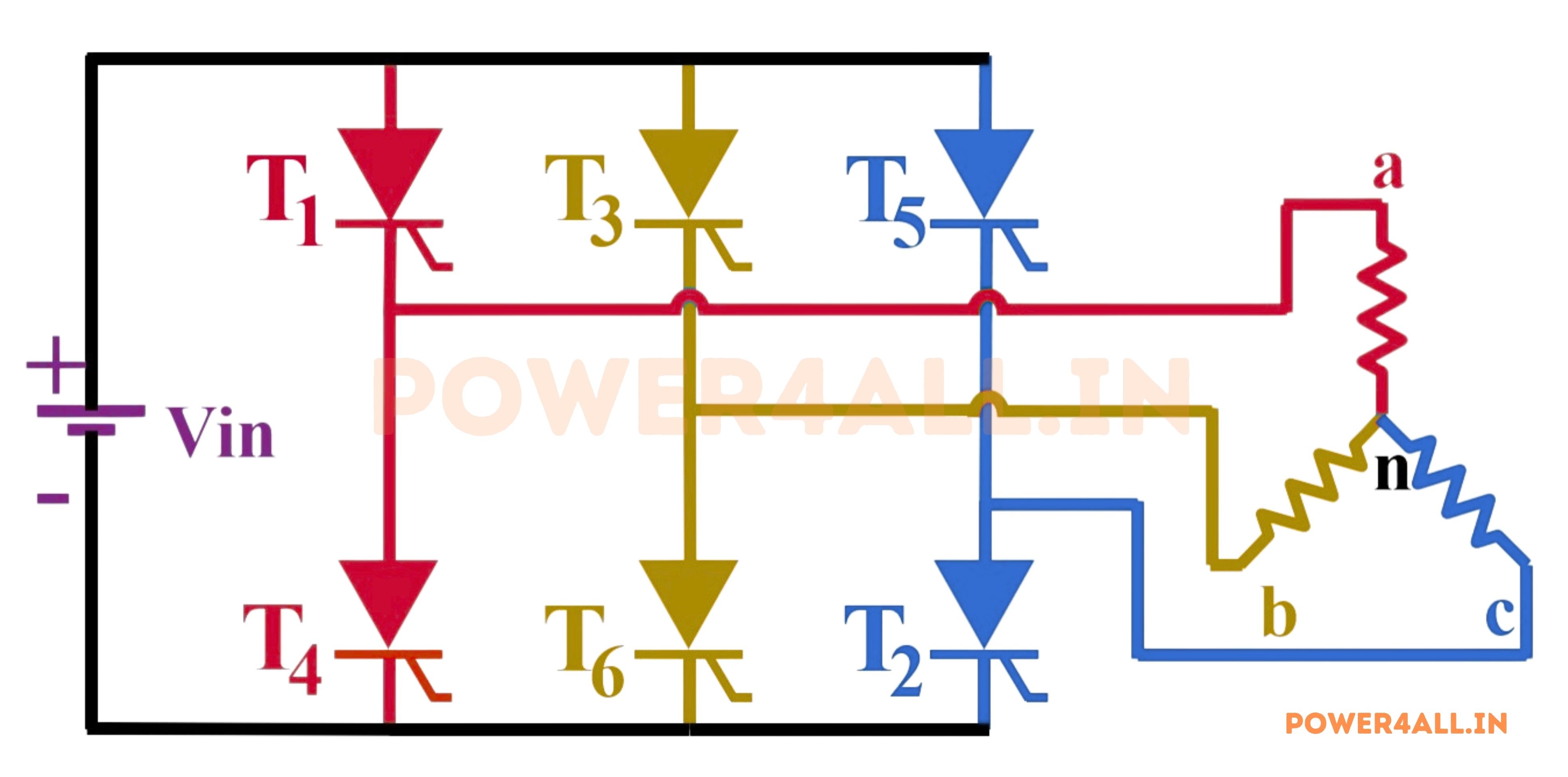
The system consists of three legs, each incorporating two thyristors. The lower leg accommodates even-numbered thyristors, while the upper leg incorporates odd-numbered thyristors. A star-connected load is accessed at the midpoint of each leg, where the two thyristors are situated.
120 Degree Conduction Mode
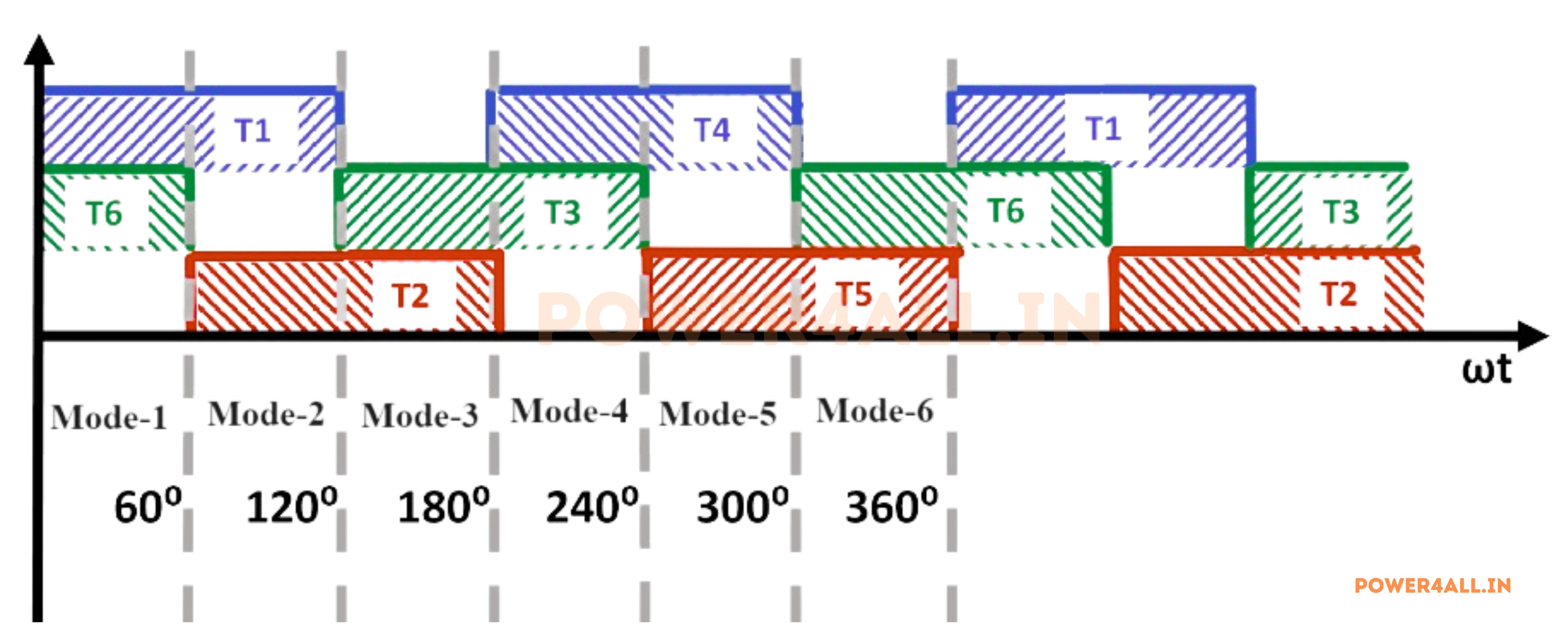
The transmission periods of different thyristors for each 60-degree segment of the full 360-degree cycle are illustrated in the figure below. There are six distinct methods for utilization. It is notable that each thyristor conducts for 2 * 60 degrees, resulting in a total conduction period of 120 degrees across the entire cycle.
Each pair of thyristors within a leg operates 180 degrees out of phase relative to the other pair. Consequently, only one thyristor conducts within each leg at any given time. Additionally, it is observable that each thyristor is 120 degrees out of phase with the adjacent thyristor in the subsequent leg.
Figure below Operating periods of the thyristors for every 60 degree in 120 degree conduction mode of three phase inverter.
Mode 1: 0° to 60° Operation
In Mode 1 (0° to 60°), thyristors T1 and T6 are conducting. During this interval, current enters the load through phase a and exits through phase b. The equivalent circuit is shown in the figure below.
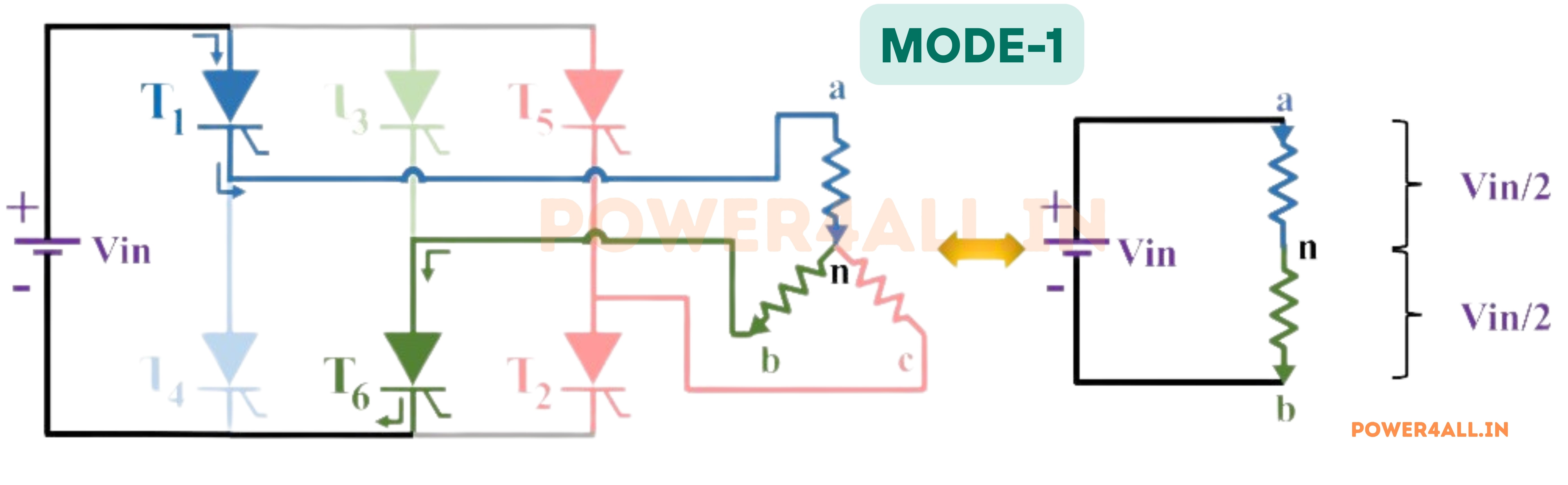
Phase-to-Neutral Voltages:
Van = Vin / 2Vbn = -Vin / 2Vcn = 0
Phase-to-Phase Voltages:
Vab = Van - Vbn = VinVbc = Vbn - Vcn = -Vin / 2Vca = Vcn - Van = -Vin / 2
Mode 2: 60° to 120° Operation
In Mode 2 (60° to 120°), thyristors T1 and T2 are conducting. Here, current flows into phase a and exits through phase c. The equivalent circuit for this mode is shown below.
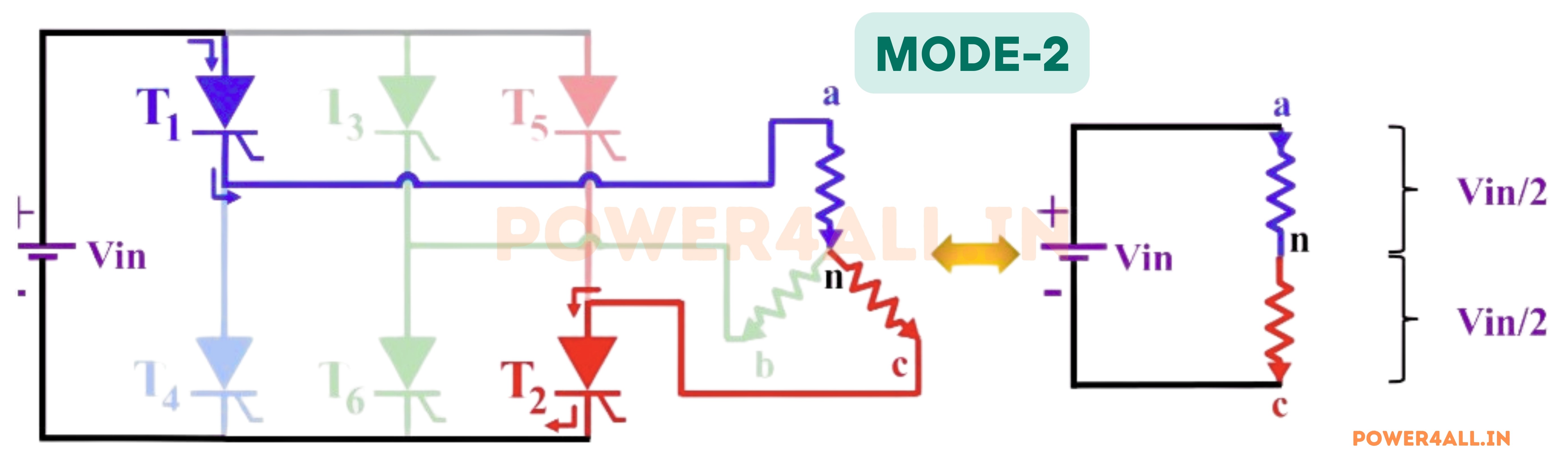
Phase-to-Neutral Voltages:
Van = Vin / 2Vbn = 0Vcn = -Vin / 2
Phase-to-Phase Voltages:
Vab = Van - Vbn = Vin / 2Vbc = Vbn - Vcn = Vin / 2Vca = Vcn - Van = -Vin
Mode 3: 120° to 180° Operation
In Mode 3 (120° to 180°), thyristors T2 and T3 are conducting. Current enters the load through phase b and exits through phase c. The equivalent circuit diagram is shown below.
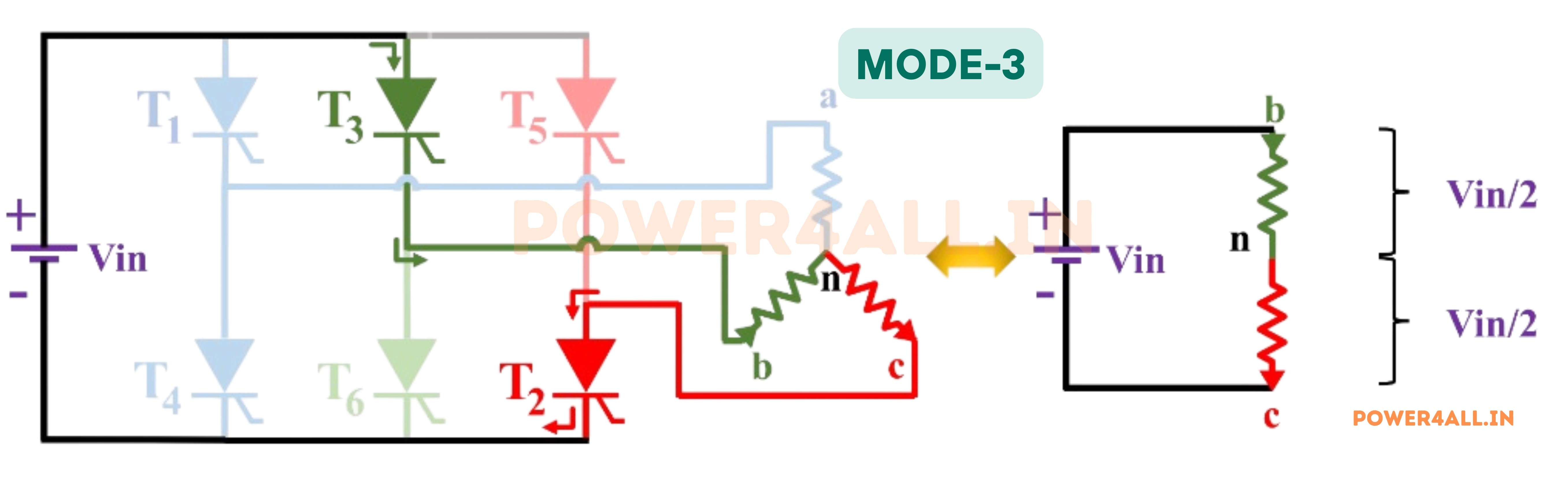
Phase-to-Neutral Voltages:
Van = 0Vbn = Vin / 2Vcn = -Vin / 2
Phase-to-Phase Voltages:
Vab = Van - Vbn = -Vin / 2Vbc = Vbn - Vcn = VinVca = Vcn - Van = -Vin / 2
Mode 4: 180° to 240° Operation
In Mode 4 (180° to 240°), thyristors T3 and T4 are conducting. Here, current enters phase b and exits through phase a. The equivalent circuit for this mode is depicted below.
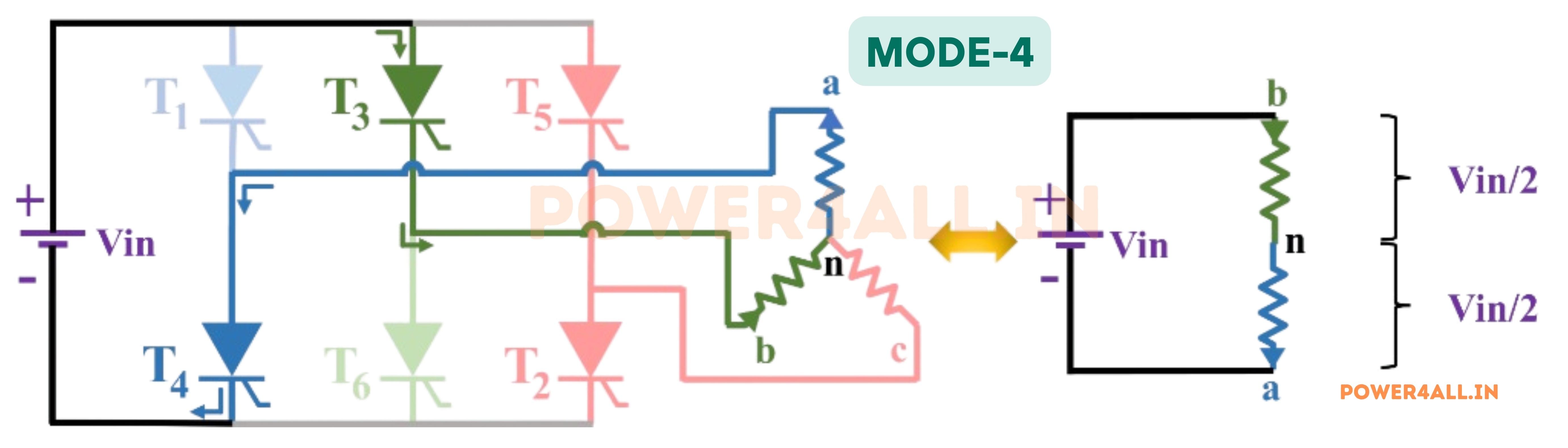
Phase-to-Neutral Voltages:
Van = -Vin / 2Vbn = Vin / 2Vcn = 0
Phase-to-Phase Voltages:
Vab = Van - Vbn = -VinVbc = Vbn - Vcn = Vin / 2Vca = Vcn - Van = Vin / 2
Mode 5: 240° to 300° Operation
In Mode 5 (240° to 300°), thyristors T4 and T5 are conducting. Current enters the load through phase c and exits via phase a. The equivalent circuit is shown below.
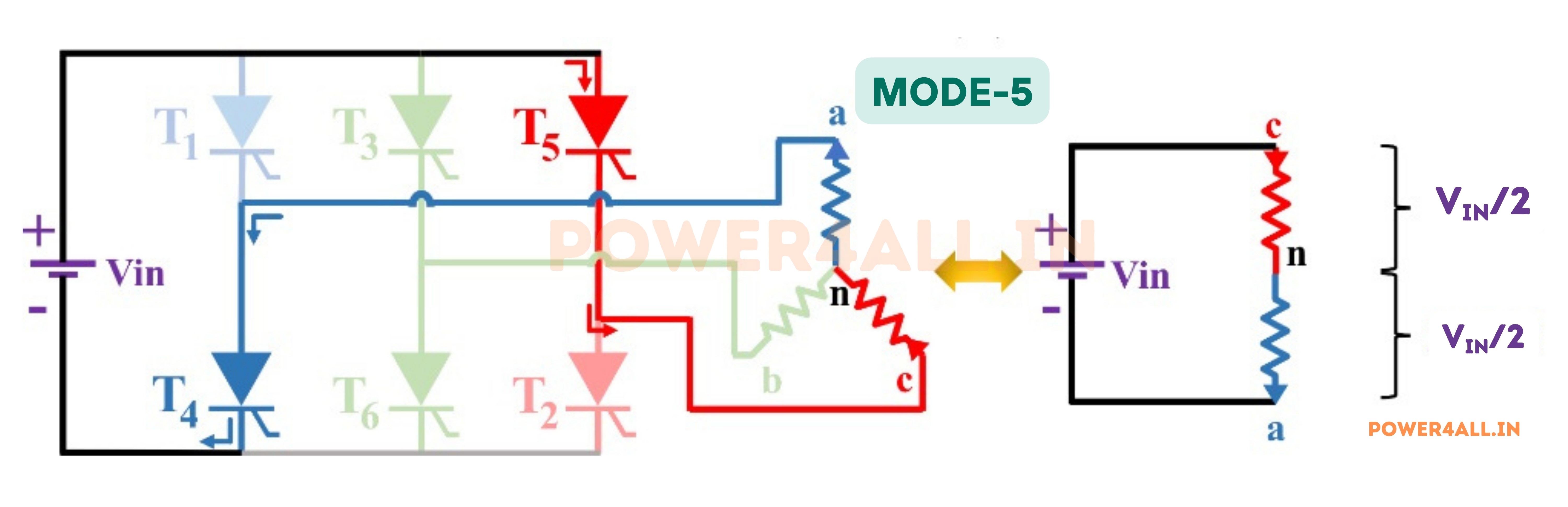
Phase-to-Neutral Voltages:
Van = -Vin / 2Vbn = 0Vcn = Vin / 2
Phase-to-Phase Voltages:
Vab = Van - Vbn = -Vin / 2Vbc = Vbn - Vcn = -Vin / 2Vca = Vcn - Van = Vin
Mode 6: 300° to 360° Operation
In Mode 6 (300° to 360°), thyristors T5 and T6 are conducting. Current enters the load through phase c and exits via phase b. The equivalent circuit diagram is shown below.
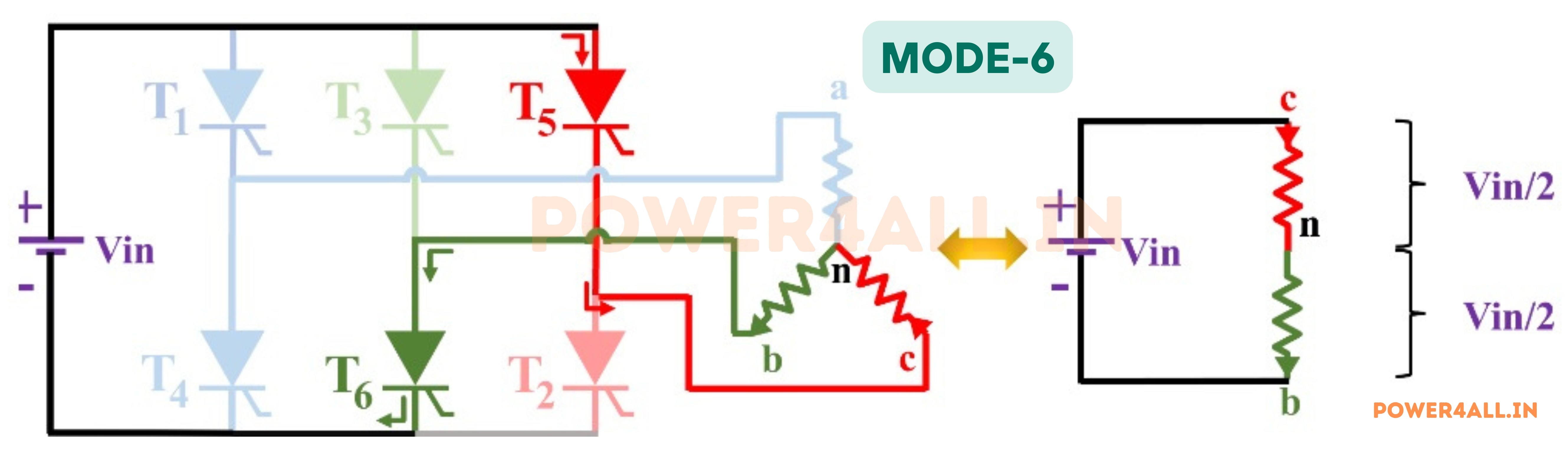
Phase-to-Neutral Voltages:
Van = 0Vbn = -Vin / 2Vcn = Vin / 2
Phase-to-Phase Voltages:
Vab = Van - Vbn = Vin / 2Vbc = Vbn - Vcn = -VinVca = Vcn - Van = Vin / 2
Output Voltage Waveform of 120° Mode Inverter:
The figure below illustrates the phase voltages and line voltage waveform of a three-phase inverter in 120-degree conduction mode. The waveform is periodic, with each cycle lasting 360 degrees. The voltage levels during each segment are determined by the conduction states of the thyristors, ensuring that the output remains balanced across all three phases.

Advantages
- Simplicity in Design: The 120-degree conduction method is simpler to implement compared to more complex methods like the 180-degree conduction method. This can lead to easier design and implementation.
- Reduced Switching Losses: Because each transistor conducts for 120 degrees of the electrical cycle, there are fewer switching events compared to methods where transistors might conduct for 180 degrees. This reduction in switching events can lead to lower switching losses and increased efficiency.
- Cost-Effective: The simpler design and fewer components required for a 120-degree inverter can make it more cost-effective to manufacture.
- Thermal Management: With each transistor conducting for only 120 degrees, the thermal load is more evenly distributed, which can help in managing the thermal performance of the inverter more effectively.
- Reduced Harmonic Distortion: In some cases, the 120-degree conduction method can result in lower harmonic distortion in the output waveform compared to other conduction methods.
Disadvantages
- Lower Output Voltage: One of the significant disadvantages of a 120-degree inverter is that it typically produces a lower output voltage compared to a 180-degree inverter. This can be a limitation in applications requiring higher voltage levels.
- Current Waveform Distortion: The current waveform in a 120-degree inverter is less smooth and has more ripples compared to a 180-degree inverter. This can cause increased harmonic content and potential issues with electromagnetic interference (EMI).
- Increased Torque Ripple: In motor drive applications, the 120-degree conduction can lead to higher torque ripple, which can affect the performance and smoothness of motor operation.
- Higher Electromagnetic Interference (EMI): The switching characteristics and waveform quality of a 120-degree inverter can result in higher levels of EMI, which may necessitate additional filtering and shielding.
- Limited Applications: Due to the lower output voltage and waveform characteristics, 120-degree inverters may not be suitable for all applications, especially those requiring high precision and low harmonic distortion.
Applications
- Commonly used for three-phase AC motor drives in small and medium industrial systems.
- Popular in variable frequency drives (VFDs) for controlling the speed of pumps and fans.
- Used in renewable energy setups to connect DC sources like solar panels to three-phase AC loads.
- Helps provide three-phase backup power in compact uninterruptible power supplies (UPS).
- Suitable for laboratory experiments and teaching the basics of three-phase inverter operation.
- Employed in some electric vehicle chargers and small industrial automation equipment.