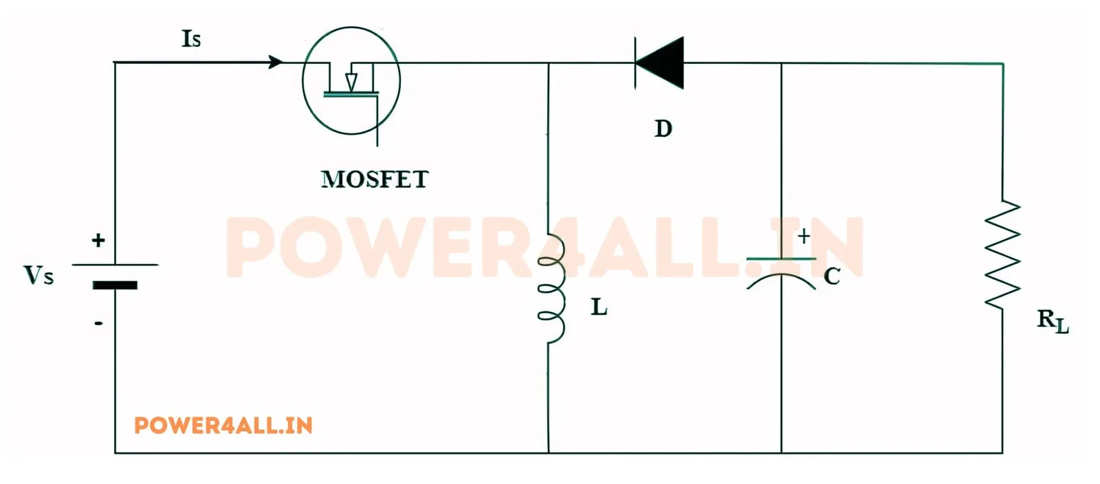
Example 1: Step-Up (24V to -48V)
Given: Vin=24V, Vout=-48V, Pout=240W, Ripple=20%, fsw=50kHz
- Duty Cycle: D = 48/(48+24) = 0.6667 (66.67%)
- Output Current: Iout = 240/48 = 5A
- Input Current: Iin = (240/24) = 10A
- Inductor Ripple: ΔIL = 0.2×10 = 2A
- Inductor: L = (24×0.6667)/(2×50000) = 160μH
- Capacitor: C ≈ 6.25μF (ΔVout = 4.8V)
- Load Resistor: R = 48/5 = 9.6Ω
Example 2: Step-Down (36V to -12V)
Given: Vin=36V, Vout=-12V, Pout=60W, Ripple=15%, fsw=100kHz
- Duty Cycle: D = 12/(12+36) = 0.25 (25%)
- Output Current: Iout = 60/12 = 5A
- Input Current: Iin = 60/36 = 1.67A
- Inductor Ripple: ΔIL = 0.15×1.67 = 0.25A
- Inductor: L = (36×0.25)/(0.25×100000) = 360μH
- Capacitor: C ≈ 0.78μF (ΔVout = 1.2V)
- Load Resistor: R = 12/5 = 2.4Ω
Example 3: High Power Conversion (48V to -72V)
Given: Vin=48V, Vout=-72V, Pout=500W, Ripple=10%, fsw=75kHz
- Duty Cycle: D = 72/(72+48) = 0.6 (60%)
- Output Current: Iout = 500/72 = 6.94A
- Input Current: Iin = 500/48 = 10.42A
- Inductor Ripple: ΔIL = 0.1×10.42 = 1.04A
- Inductor: L = (48×0.6)/(1.04×75000) = 369μH
- Capacitor: C ≈ 1.73μF (ΔVout = 7.2V)
- Load Resistor: R = 72/6.94 = 10.37Ω
A buck-boost converter is a switch-mode DC-DC converter that can produce an output voltage either higher or lower than its input — combining the abilities of a buck and a boost in one circuit. In its classic form the output is also inverted (negative with respect to the input), which makes it ideal for generating a negative rail or for supplies where the input voltage swings across the output value.
How it works
When the switch is on, the inductor is charged directly from the input; the diode is reverse-biased and the load is held up by the output capacitor. When the switch turns off, the inductor reverses its terminal voltage and dumps its stored energy into the output through the diode — producing a voltage of opposite polarity. The magnitude follows |Vout| = Vin × D / (1 − D), so D < 0.5 steps the voltage down and D > 0.5 steps it up, with D = 0.5 giving |Vout| = Vin.
Why it is useful
Its key advantage is a single stage that regulates through the input = output crossover point. A 3-cell lithium battery, for instance, ranges from about 9 V (empty) to 12.6 V (full); a plain buck or boost cannot hold a steady 12 V across that range, but a buck-boost can. The trade-offs are higher peak currents and more voltage stress on the switch and diode (they see Vin + |Vout|), so components must be rated accordingly.
Where buck-boost converters are used
Battery-powered equipment where the pack voltage crosses the load voltage, negative-rail generation for op-amps and sensors, automotive supplies that must ride through cranking dips and load-dump surges, and portable devices needing a fixed rail from a wide input. Non-inverting four-switch buck-boost variants keep the output positive for these applications.
Common questions
Why is the output negative? The classic single-switch topology inverts polarity by design. If you need a positive output that can step up and down, use a four-switch buck-boost, a SEPIC, or a ZETA converter.
How does it compare with SEPIC/ZETA? All three step up or down; the basic buck-boost is simplest but inverting, while SEPIC and ZETA add a coupling capacitor (and a second inductor) to keep the output positive.