three-phase to three-phase cycloconverter
three-phase to three-phase cycloconverter in Power Electronics: Types, Working, and Applications
- Introduction
- Three Phase to Single Phase Cycloconverter
- Operation of Three-Phase to Single-Phase Cycloconverter
- Waveform of Three phase to Single phase Cycloconverter
- Three Phase to Three Phase Cycloconverter
- Advantages of Three-Phase to Three-Phase Cycloconverters
- Disadvantages of Three-Phase to Three-Phase Cycloconverters
- Applications of Three-Phase to Three-Phase Cycloconverter
- Three-Phase to Three-Phase Cycloconverter FAQs
- Related Topics
Introduction
A three-phase inverter is an essential power electronic circuit that converts direct current (DC) into three-phase alternating current (AC). This process is vital for running industrial motors, large pumps, compressors, and many other types of equipment that require a balanced three-phase AC supply. In many systems, the DC input is obtained by first rectifying AC from the grid, then smoothing it with filters before it enters the inverter stage.
The core of a three-phase inverter is a set of electronic switches-often six in total-that operate in a precise sequence. By rapidly turning these switches on and off in the correct pattern, the inverter creates three separate AC waveforms, each shifted by 120 degrees. Modern inverters use advanced control methods like pulse-width modulation (PWM) to produce smoother, more sinusoidal output, which helps reduce noise and improves efficiency for connected loads.
Three-phase inverters are widely used in motor drives, renewable energy systems, uninterruptible power supplies, and active filters. Their ability to control the amplitude, frequency, and phase of the output makes them highly versatile for both industrial and commercial applications.
Types of Three-Phase Inverters
- Three-Phase to Single-Phase Inverter: Converts three-phase DC (from a rectified three-phase supply) into a single-phase AC output. This configuration is less common but can be used where a single-phase load needs to be powered from a three-phase DC source.
- Three-Phase to Three-Phase Inverter: The most common type, designed to generate a balanced three-phase AC output from a DC source. It is widely used for motor drives and industrial power systems.
Three Phase to Single Phase Cycloconverter
The three-phase to single-phase cycloconverter is a device that takes in a three-phase AC supply and produces a single-phase AC output. While the frequency of the input stays the same, the output frequency can be adjusted as needed-usually set lower than the input. This is why it’s called a step-down cycloconverter.
The three-phase to single-phase cycloconverter is a device that takes in a three-phase AC supply and produces a single-phase AC output. While the frequency of the input stays the same, the output frequency can be adjusted as needed-usually set lower than the input. This is why it’s called a step-down cycloconverter.
These cycloconverters can be built using either a half-wave or a full-bridge design. In both cases, the thyristors work together to create the desired single-phase output by piecing together sections of the input voltage. The diagrams below show typical circuits for both half-wave and full-wave versions.
Operation of Three-Phase to Single-Phase Cycloconverter
In this cycloconverter, the control system decides when each group of thyristors should conduct. During the positive half of the input cycle, the positive group is triggered to allow current to flow to the load. When the input swings negative, the negative group is activated to deliver current in the opposite direction. By carefully timing these switching events, the output voltage can be shaped to the desired frequency and waveform.
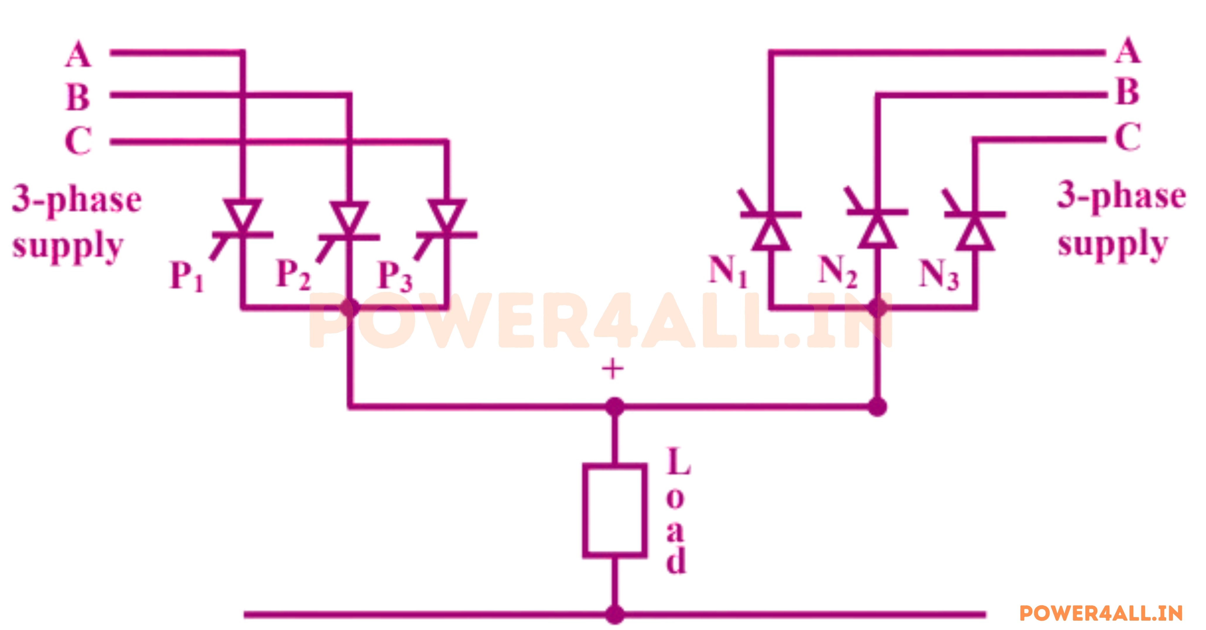
In a bridge-type cycloconverter, both the positive and negative converter groups are capable of producing voltages of either polarity. However, the positive group only supplies positive current to the load, while the negative group only supplies negative current. At any moment, only one converter group is active, ensuring safe and controlled operation.
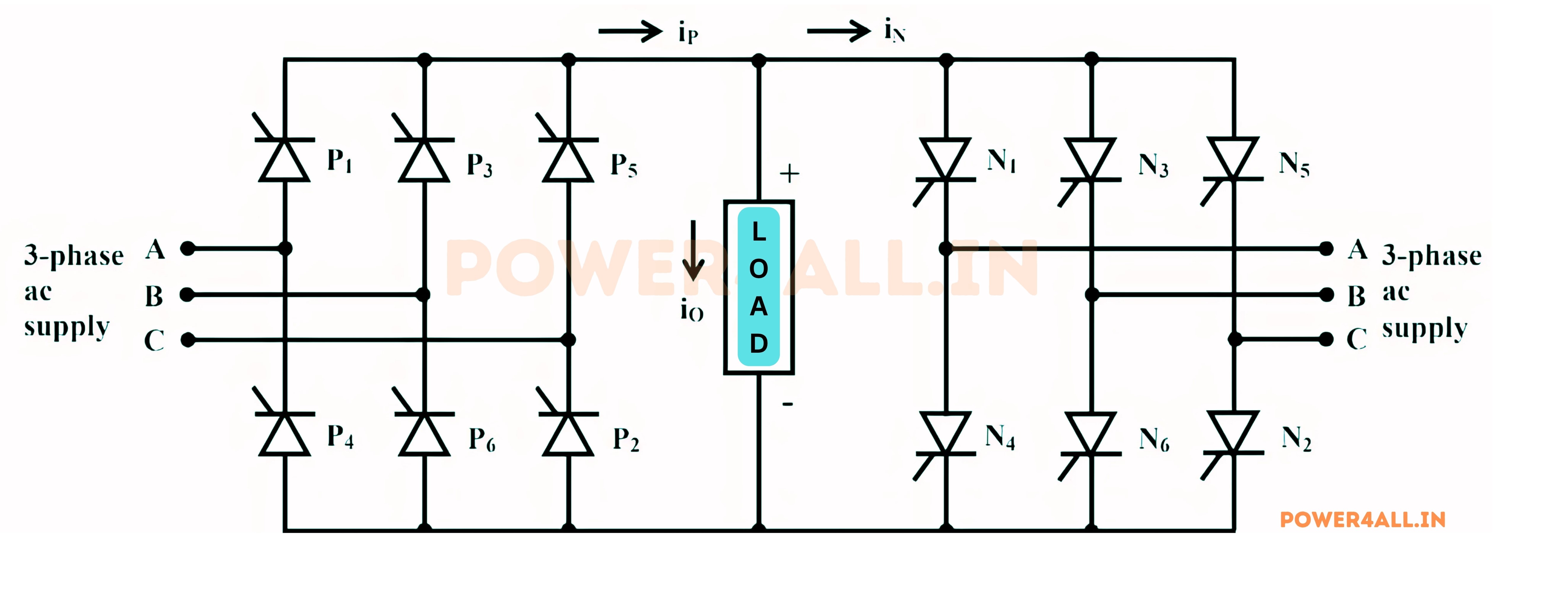
Thanks to this arrangement, the cycloconverter can operate in all four quadrants. This means it can handle both rectification (converting AC to DC and back) and inversion (reversing voltage and current directions), allowing for flexible control of the output. The four modes are: (+V, +i), (-V, -i) for rectification, and (+V, -i), (-V, +i) for inversion. This versatility makes the cycloconverter suitable for a wide range of AC control applications.
Waveform of Three-Phase to Single-Phase Cycloconverter
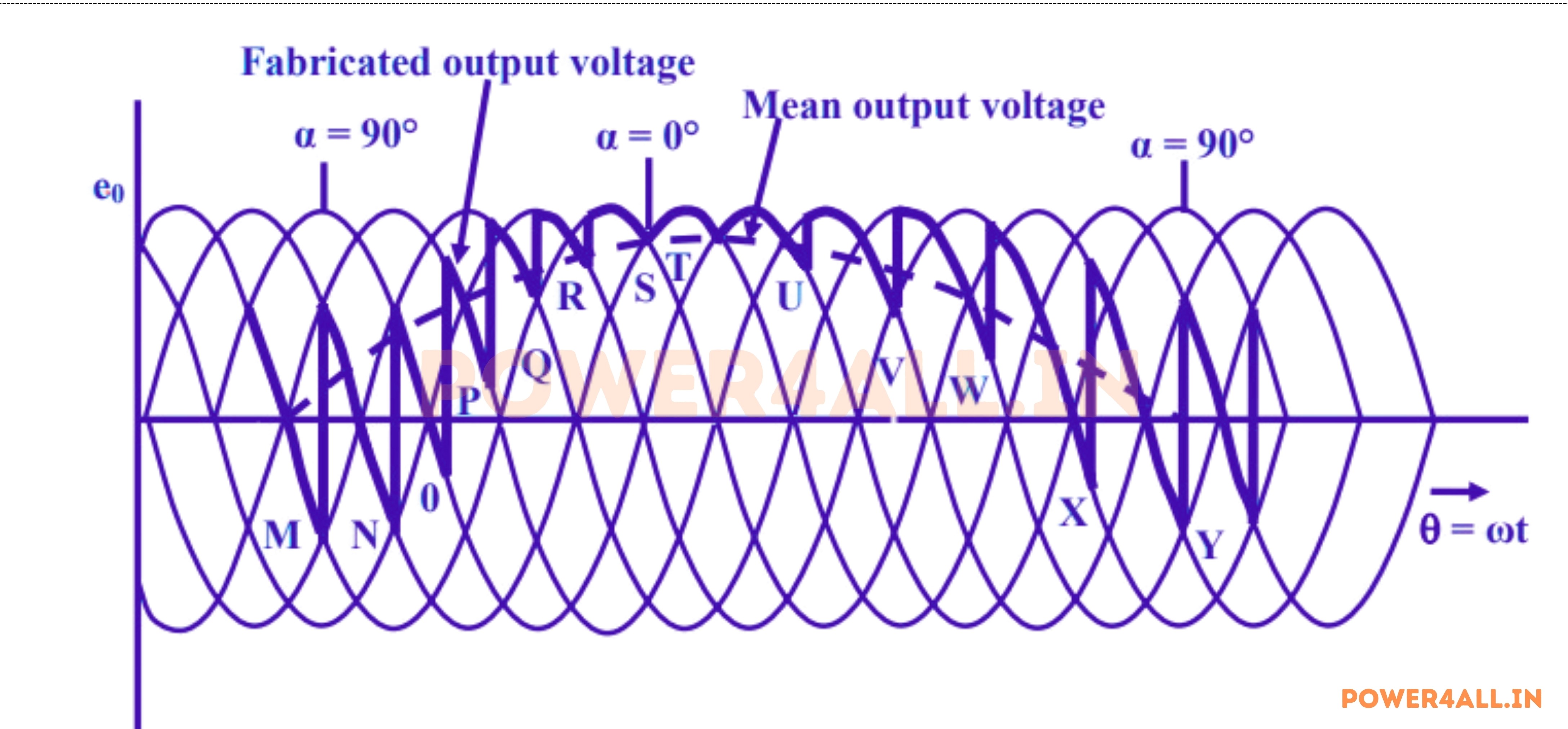
The output waveform of a three-phase to single-phase cycloconverter is formed by carefully controlling when each group of thyristors conducts. By adjusting the firing angle of these thyristors, the circuit selects and combines segments of the three-phase input to build a single-phase output at a lower frequency.
In the diagram below, you can see how the output voltage is pieced together from different parts of the input waveforms. At the start (point M), the firing angle is set to 90 degrees and is gradually reduced to zero by point S. After that, from point T to Y, the firing angle is increased again. This gradual change in firing angles allows the cycloconverter to control both the shape and frequency of the output voltage.
By varying the timing of the thyristor triggers, the cycloconverter can adjust how long each segment of the input is used, which in turn sets the output frequency. The result is a stepped waveform that follows the outline of a sine wave, but at a lower frequency than the original three-phase supply.
The output frequency can be controlled by adjusting the firing angle of the thyristors. This allows for a wide range of applications, from speed control in motors to power supply for various industrial processes.
Three Phase to Three Phase Cycloconverter
A three-phase to three-phase cycloconverter is a power electronic device that directly converts an input three-phase AC voltage to an output three-phase AC voltage of a lower frequency without an intermediate DC link. This conversion is achieved by means of bidirectional switches that control the flow of current from the input to the output.
These are obtained by connecting 3 three-phase to single-phase cyclo-converters to the load. These converters can be connected in star or delta. Three phase cyclo-converter of both half-wave and bridge types are shown in figure below.
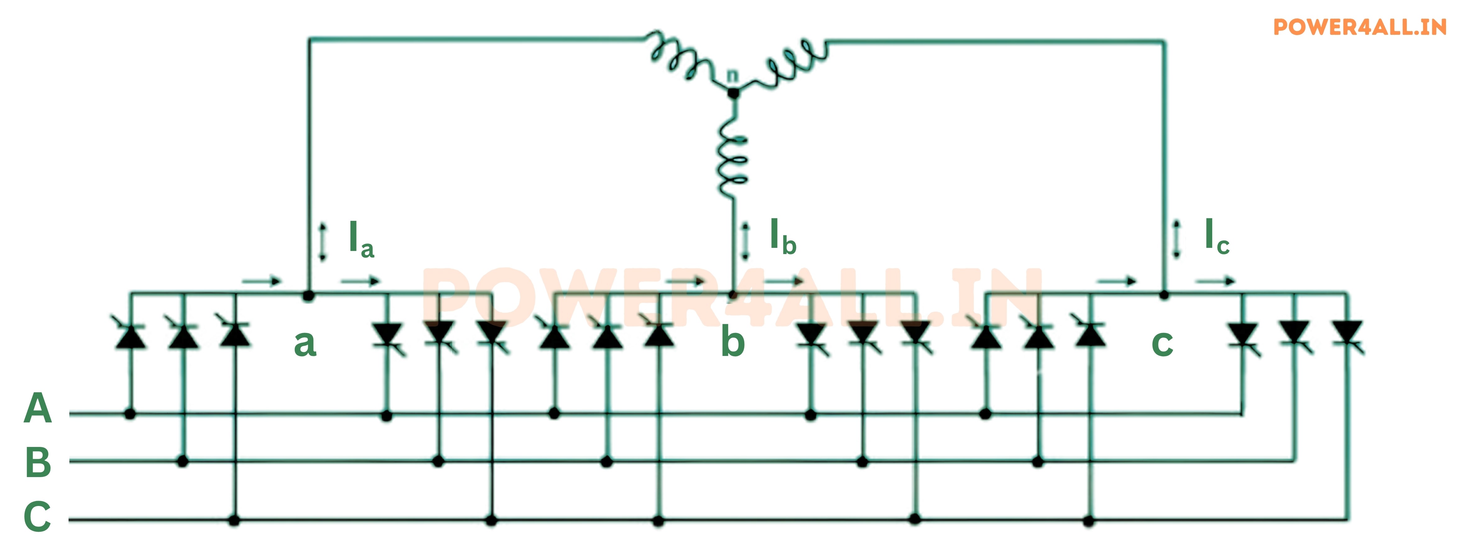
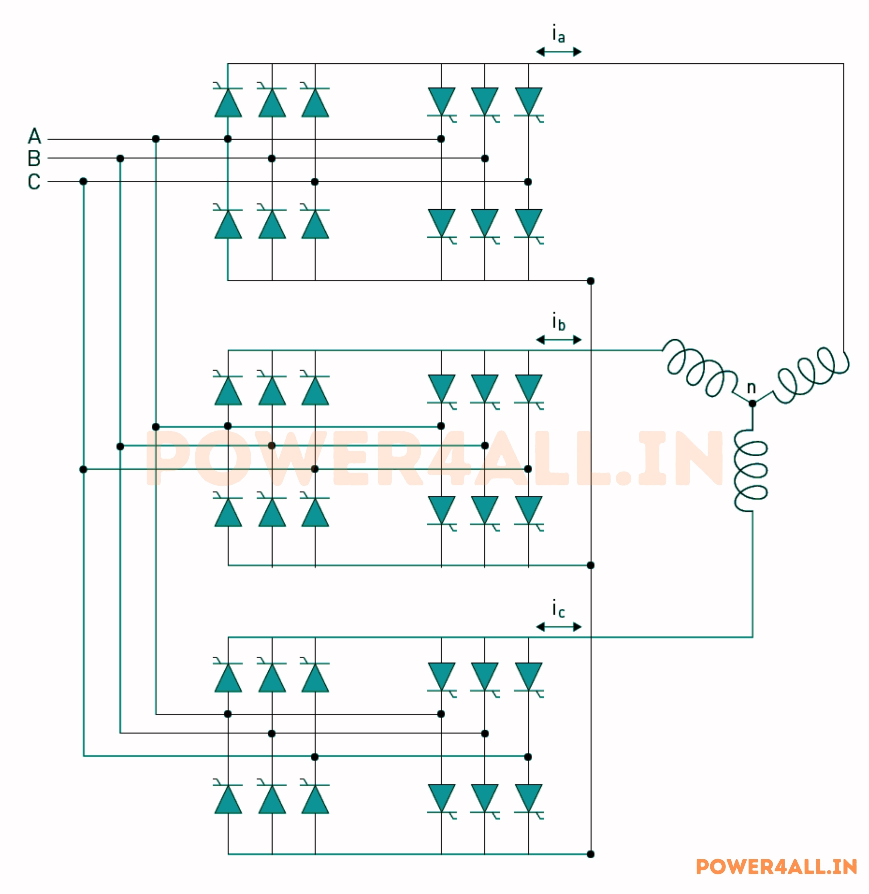
This converter is sometimes called an 18-thyristor or 3-pulse cycloconverter when using the half-wave type, and a In each cycle, the positive group conducts during the positive half, carrying current to the load, while the negative group takes over during the negative half. By changing how long each group is on (the firing or delay angle), you can adjust the average output voltage and the output frequency. The firing sequence of the switches is key to setting the output waveform.
If the load is balanced, there’s no need for a neutral connection, which helps simplify the system. Three-phase cycloconverters are popular in industry because they can handle large currents and deliver a steady, reliable output. Their design allows for variable frequency operation, and using more thyristors helps reduce unwanted ripple in the output voltage, making them well-suited for driving big motors or other demanding loads.
Advantages of Three-Phase to Three-Phase Cycloconverter
- Precise Frequency Control: Allows smooth and accurate adjustment of output frequency, which is essential for running large motors at different speeds.
- Direct AC-to-AC Conversion: Converts three-phase AC at one frequency directly into three-phase AC at a lower frequency, without needing a DC link.
- Handles High Power: Well-suited for heavy-duty industrial applications, as it can deliver large amounts of power to big machines.
- Four-Quadrant Operation: Capable of both motoring and braking (regeneration), making it flexible for demanding drive systems.
- No Bulky Energy Storage: Does not require large capacitors or inductors, keeping the design more straightforward.
- Reliable for Continuous Use: Designed to operate for long periods, making it a dependable choice for industries like steel mills and mining.
Disadvantages of Three-Phase to Three-Phase Cycloconverter
- Complex Circuitry: Requires a large number of switching devices and a sophisticated control system, especially as power levels increase.
- Harmonic Distortion: The output waveform contains harmonics, which can cause extra heating in motors and may require filters to reduce electrical noise.
- Size and Weight: The need for many components makes the system bulky and heavy, particularly in high-power installations.
- Lower Efficiency at Low Frequencies: Efficiency can drop when the output frequency is much lower than the input, due to increased switching losses.
- Limited Output Frequency Range: The output frequency is typically limited to about one-third of the input frequency for reliable operation.
- Cost: More expensive than simpler converters, mainly due to the number of power devices and the complexity of the control system.
Applications of Three-Phase to Three-Phase Cycloconverter
- Heavy Motor Drives: Used to control the speed and torque of large motors in steel mills, cement plants, and mining operations.
- Marine Propulsion: Provides variable speed control for ship engines, improving maneuverability and efficiency.
- Traction Systems: Powers electric trains and trams, allowing for smooth acceleration and braking.
- Renewable Energy: Matches the frequency of wind or hydro generators to the grid, making integration easier.
- Power Generation: Adjusts generator output frequency to meet grid requirements, especially in systems with variable-speed turbines.
- High-Power Test Benches: Supplies adjustable-frequency three-phase power for testing industrial equipment and research setups.