Complete Inductor Mastery Guide
Master the fundamentals of inductors - from basic concepts and value identification to advanced applications in modern electronics and circuit design
Complete Learning Path - Inductor Fundamentals to Applications
Navigate through comprehensive coverage of inductors from basic principles to advanced applications
What is an Inductor?
An inductor is a passive electronic component that stores energy in a magnetic field when electric current flows through it. Think of it like a magnetic energy reservoir - when current changes, the inductor opposes that change by releasing or absorbing energy, making it essential for filtering, energy storage, and frequency control in electronic circuits.
V = -L × (dI/dt)
Voltage across inductor equals inductance times rate of current change
Why Inductors are Essential
Inductors might seem like simple coils of wire, but they're crucial components that enable many modern electronic functions. Their ability to store magnetic energy and oppose current changes makes them indispensable in power supplies, filters, and RF circuits.
Inductor Symbol and Units
Circuit Symbols
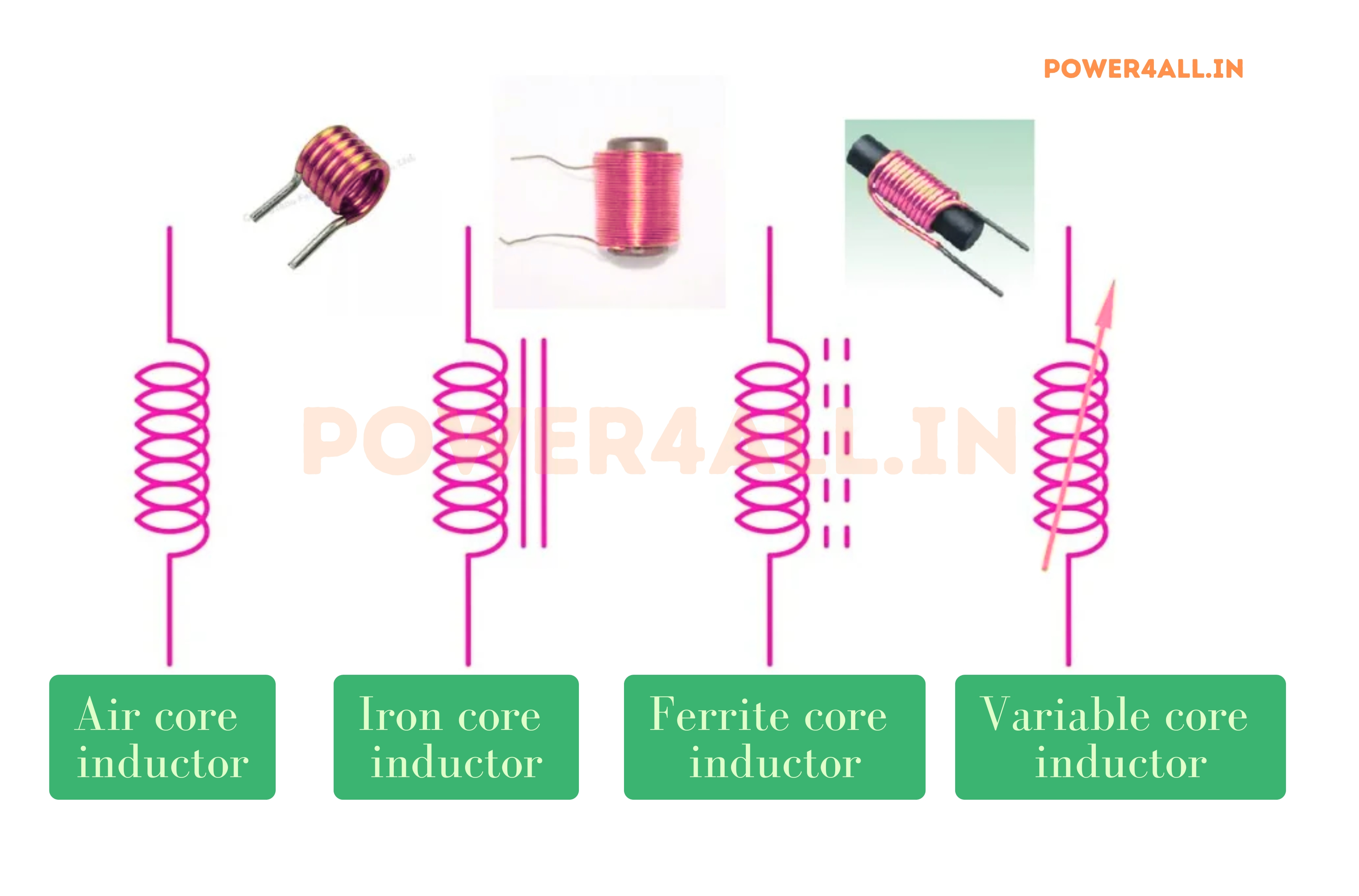
- Air core: Simple coil symbol (curved lines)
- Iron core: Coil with solid line through center
- Ferrite core: Coil with dashed line through center
- Variable inductor: Coil with arrow through it
- Coupled inductors: Two coils with coupling indicator
Units of Measurement
- Henry (H): Basic unit of inductance
- Millihenry (mH): 0.001 henries (most common)
- Microhenry (μH): 0.000001 henries
- Nanohenry (nH): 0.000000001 henries
- Named after: Joseph Henry, American physicist
Inductor Fundamentals: How They Work
Understanding how inductors work involves exploring electromagnetic induction, magnetic field theory, and the physical construction that enables energy storage. This knowledge is essential for selecting the right inductor and understanding its behavior in circuits.
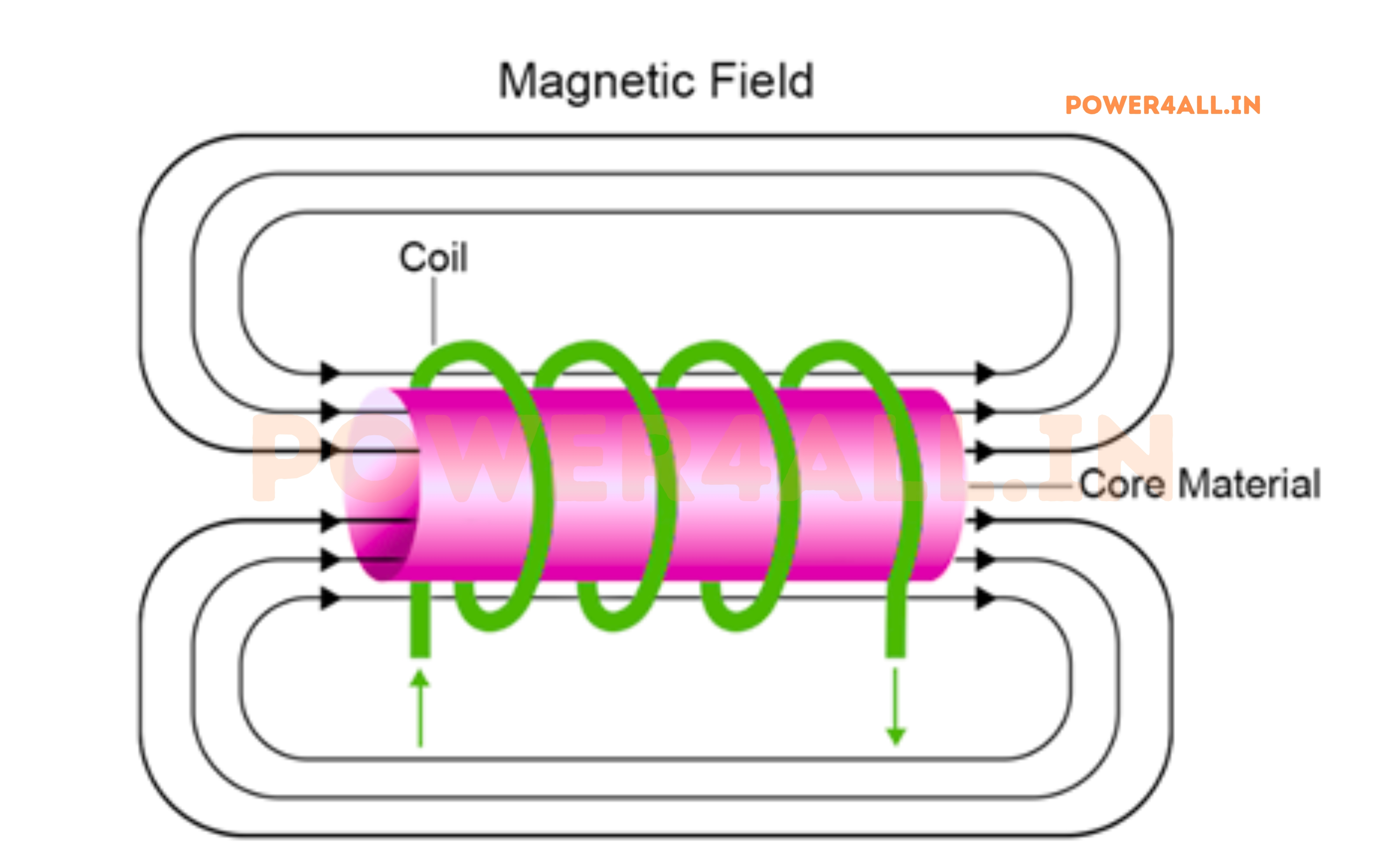
The Physics of Inductance
What Creates Electrical Inductance?
Inductance occurs when current flowing through a conductor creates a magnetic field around it. When this current changes, the changing magnetic field induces a voltage that opposes the current change - this is Lenz's Law in action.
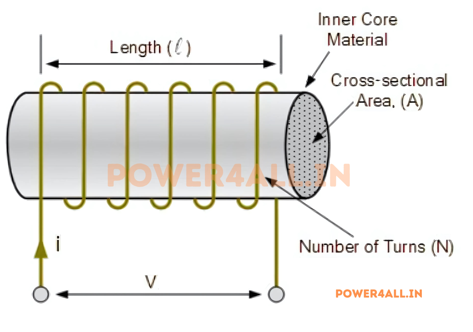
Microscopic View of Inductance
L = μ × N² × A / l
Inductance = Permeability × Turns² × Area / Length
Factors Affecting Inductance
Inductor Construction Materials
Air Core Inductors
No magnetic core - wire wound around air space
Construction Details
- Core material: Air (μ = 1, no saturation)
- Wire types: Copper, silver-plated copper, litz wire
- Forms: Ceramic, plastic, or self-supporting
- Inductance range: nH to low mH values
- Advantages: No core losses, high Q factor, linear
- Disadvantages: Large size for high inductance
Applications
- RF circuits: High frequency applications
- Precision filters: No non-linear effects
- Tank circuits: Oscillators and resonant circuits
- Antenna tuning: Radio frequency matching
Iron Core Inductors
Ferromagnetic core for high inductance
Core Materials
- Laminated iron: Thin sheets reduce eddy currents
- Silicon steel: Low loss electrical steel
- Permalloy: Nickel-iron alloy for high permeability
- Amorphous cores: Very low loss modern materials
- Permeability: 100-100,000 times higher than air
- Saturation: Limited by core saturation current
Applications
- Power supplies: Filter chokes and transformers
- Motor drives: Line reactors and filters
- Audio equipment: Low frequency inductors
- Grid applications: Power factor correction
Ferrite Core Inductors
Ceramic magnetic material for high frequency
Ferrite Characteristics
- Material: Iron oxide with other metal oxides
- High resistivity: Reduces eddy current losses
- Frequency range: kHz to GHz applications
- Shapes: Toroids, E-cores, pot cores, rods
- Permeability: 10-10,000 depending on material
- Temperature stable: Good performance over wide temperature range
Common Ferrite Types
- MnZn ferrites: Low frequency, high permeability
- NiZn ferrites: High frequency, lower permeability
- Soft ferrites: Easy magnetization/demagnetization
- Hard ferrites: Permanent magnet applications
Frequency Effects on Inductors
How Frequency Changes Affect Inductor Performance
Inductors behave differently at different frequencies due to parasitic elements, core losses, and skin effect. Understanding these effects is crucial for proper inductor selection.
XL = 2π × f × L
Inductive reactance increases with frequency
Frequency-Dependent Effects
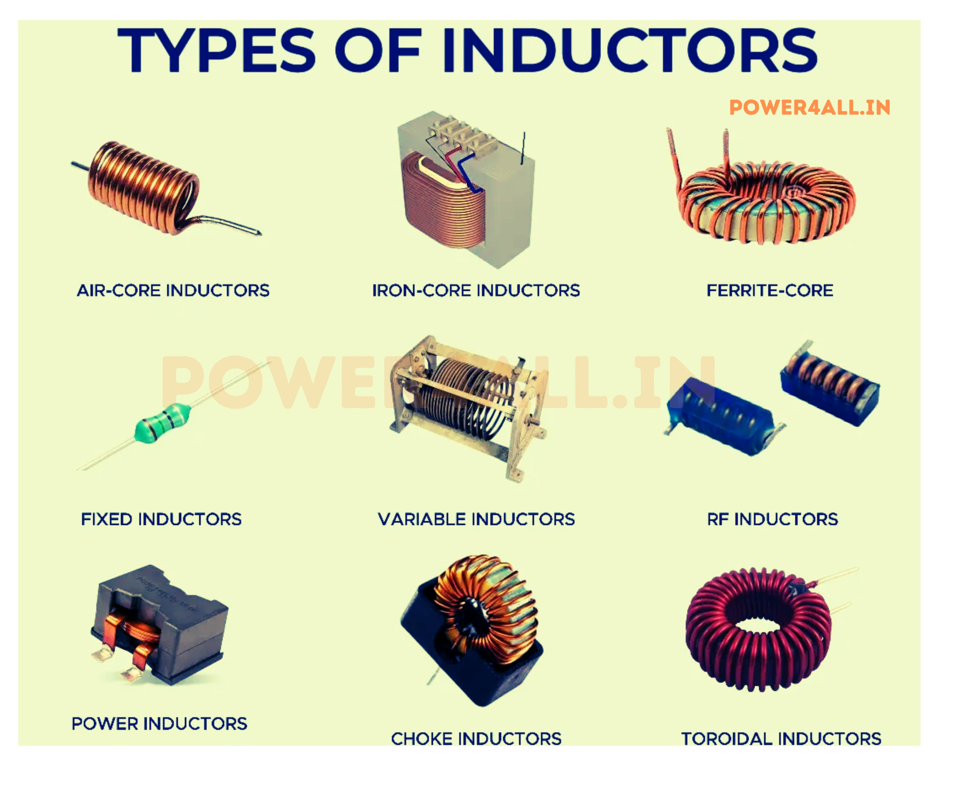
Types of Inductors: Complete Classification
Inductors come in many different types, each optimized for specific applications, frequency ranges, and performance requirements. Understanding the various types helps in selecting the right inductor for your particular need, whether it's power filtering, RF applications, or precision timing circuits.
Fixed Value Inductors
Through-Hole Inductors
Traditional inductors with leads for PCB mounting
Common Package Types
- Axial leaded: Color-coded like resistors
- Radial leaded: Both leads from one end
- Toroidal: Donut-shaped with wire leads
- Bobbin core: Traditional coil form construction
- Chokes: Large inductors for power applications
Advantages
- Easy to handle and identify
- Higher current capacity
- Good for prototyping
- Replaceable in circuits
- Better heat dissipation
Surface Mount Inductors (SMD)
Compact inductors for modern electronics
Standard SMD Sizes
- 0402: 1.0mm × 0.5mm (very low inductance)
- 0603: 1.6mm × 0.8mm (RF applications)
- 0805: 2.0mm × 1.25mm (general purpose)
- 1206: 3.2mm × 1.6mm (higher current)
- 1210: 3.2mm × 2.5mm (power applications)
Construction Types
- Multilayer: Ceramic with printed spirals
- Wire wound: Traditional coil in small package
- Thin film: Deposited metal patterns
- Molded: Wire coil in molded ferrite
Power Inductors
High current inductors for power applications
Current Ratings and Features
- 1-5 A: Small switching regulators
- 10-20 A: CPU power supplies
- 50+ A: High power converters
- Low DCR: Minimizes power loss
- Saturation current: High current before saturation
Construction Features
- Thick copper wire or foil
- Powder iron or ferrite cores
- Shielded or unshielded options
- Heat sinks or thermal pads
- Low profile packages
Variable Inductors
Adjustable and Variable Inductance Components
Variable Inductors (Variometers)
Inductors with mechanically adjustable inductance values, typically using moving cores or taps on windings.
Slug-Tuned Inductors
- Adjustable core: Ferrite slug moves in/out of coil
- Tuning range: 2:1 to 10:1 inductance variation
- Applications: RF tuning, oscillator adjustment
- Adjustment: Screwdriver or allen key
- Frequency range: kHz to low MHz
Roller Inductors
- Contact roller: Moves along coil length
- Continuous variation: Smooth inductance change
- High Q factor: Low loss connection
- Applications: Antenna tuners, lab equipment
- Range: Wide inductance variation
Switched Inductors
Multiple fixed inductors switched electronically to create variable inductance.
Special Purpose Inductors
Toroidal Inductors
Donut-shaped core with excellent magnetic containment
Advantages
- Self-shielding: Magnetic field contained within core
- High efficiency: Minimal flux leakage
- Compact size: Maximum inductance per volume
- Low EMI: Reduced electromagnetic interference
- Linear characteristics: Stable over wide range
Common Mode Chokes
Dual winding inductors for EMI suppression
Operating Principle
- Differential signals: Magnetic fields cancel, low impedance
- Common mode noise: Fields add, high impedance
- Core material: High permeability ferrite
- Frequency range: kHz to GHz depending on design
RF Inductors
Specialized inductors for radio frequency applications
RF-Specific Requirements
- High Q factor: Low loss at RF frequencies
- Self-resonant frequency: High SRF for operation range
- Temperature stability: Stable over temperature
- Low parasitic capacitance: Minimal inter-winding capacitance
- Tight tolerance: Precise values for tuned circuits
Inductor Value Identification: Reading Inductance Values
Unlike resistors with their standardized color code system, inductors use various marking schemes depending on their type and manufacturer. Learning to identify inductor values is essential for circuit analysis, component replacement, and proper circuit design.
Color Code System (Traditional Inductors)
Reading Color-Coded Inductors
4-Band Reading
Similar to resistor reading but for microhenries (μH)
Band Order (left to right)
Direct Value Marking
Numerical values printed directly on component
Common Marking Formats
- With units: "100μH", "1.5mH", "47nH"
- Decimal notation: "R47" = 0.47μH, "2R2" = 2.2μH
- Scientific notation: "1005" = 100μH ± 5%
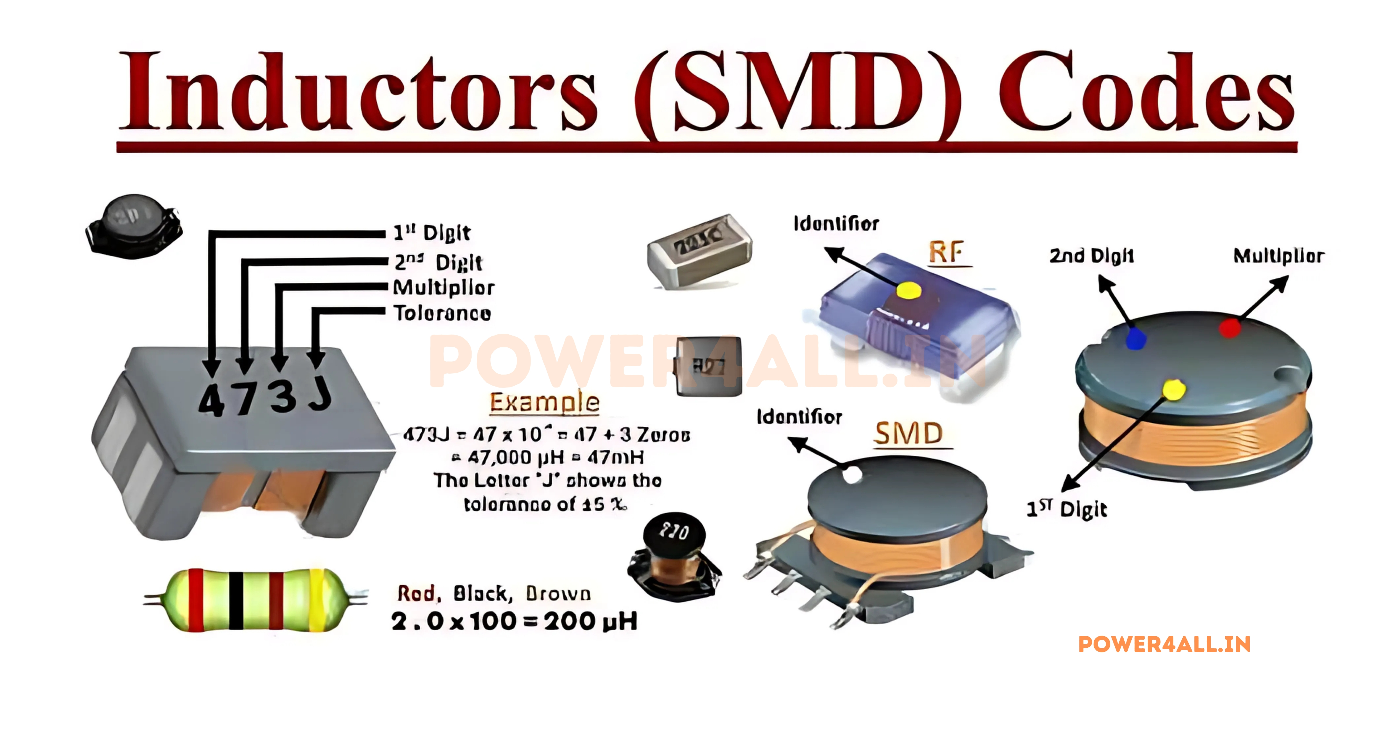
- Code system: Three digits plus tolerance letter
SMD Inductor Marking
Surface Mount Device Value Coding Systems
SMD inductors use various coding systems due to their small size. The marking system varies by manufacturer and component size.
Three-Digit Code System
Letter Code System
Inductance Calculations & Formulas
Understanding inductance calculations is essential for designing circuits with inductors, predicting their behavior at different frequencies, and calculating energy storage. These formulas help in selecting appropriate inductors and understanding their interaction with other circuit elements.
Basic Inductance Relationships
V = L × (dI/dt)
Fundamental inductor voltage-current relationship
Related Formulas
- Energy stored: E = ½ × L × I²
- Reactance: XL = 2π × f × L
- Time constant: τ = L / R
- Resonant frequency: f = 1 / (2π√LC)
Physical Inductance Calculations
Air Core Solenoid
Calculate inductance from physical dimensions
L = (μ₀ × N² × A) / l
Where μ₀ = 4π × 10⁻⁷ H/m
Toroidal Inductor
More complex calculation for toroidal cores
L = (μ × N² × A) / l_path
Where μ = μ_r × μ₀
Energy and Power Calculations
Series & Parallel Inductor Combinations
Like resistors, inductors can be connected in series and parallel to achieve desired inductance values, current ratings, and circuit characteristics. However, inductors have additional considerations including magnetic coupling, current sharing, and frequency-dependent behavior that make their combination more complex than simple mathematical relationships.
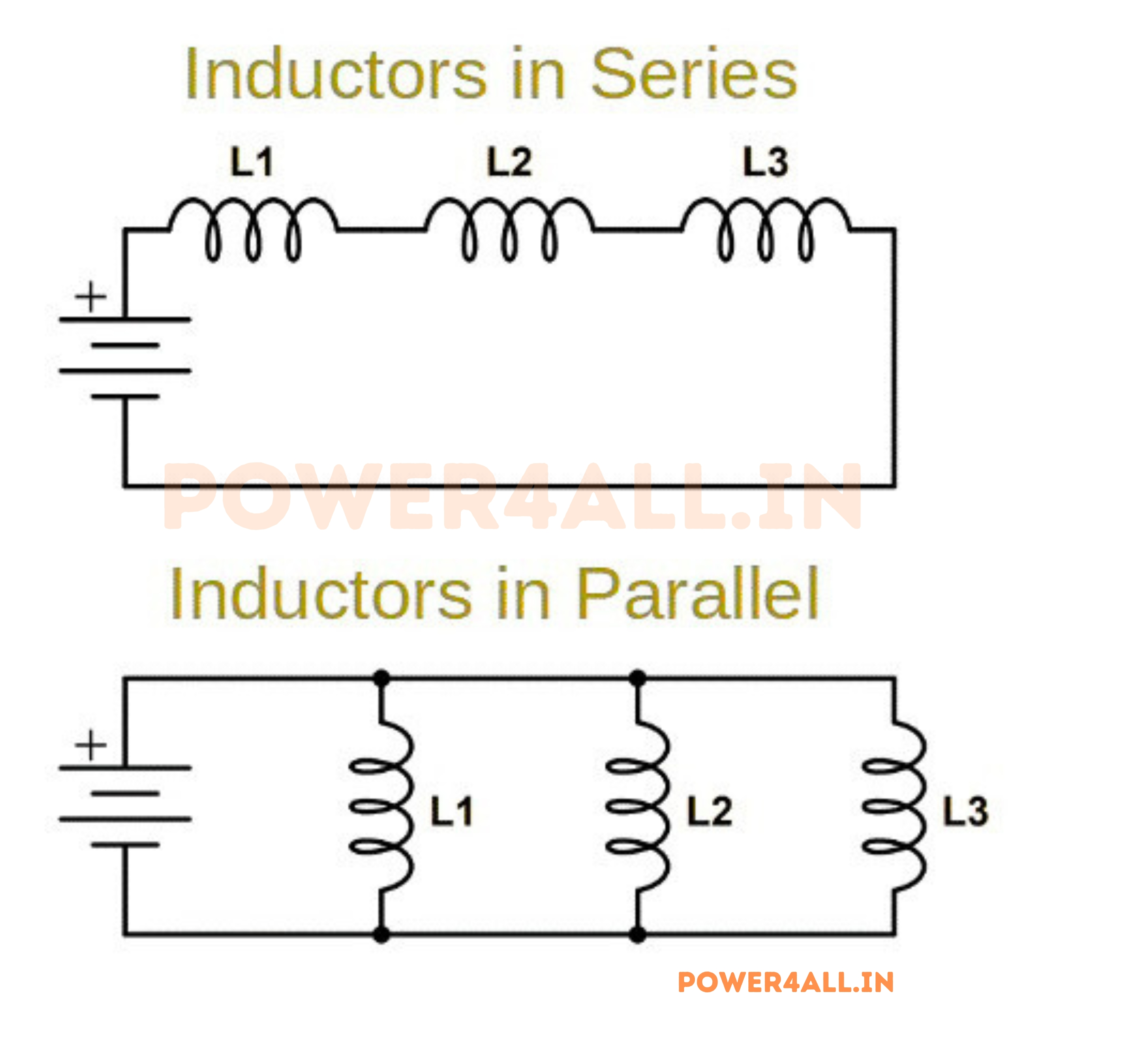
Series Inductor Combinations
Series Connection Principles
In series connections, inductors are connected end-to-end, creating a single current path through all inductors. The magnetic fields can either aid or oppose each other depending on winding polarity.
L_total = L1 + L2 + L3 + ... ± M
Total inductance including mutual inductance effects
Key Characteristics
- Same current: Identical current through all inductors
- Voltage adds: Individual voltages sum algebraically
- Higher total inductance: Sum of individual values (if no coupling)
- Mutual coupling: Can increase or decrease total inductance
Mutual Inductance Effects
How Magnetic Coupling Affects Series Combinations
When inductors are placed near each other, their magnetic fields interact through mutual inductance (M). This coupling can significantly affect the total inductance depending on physical arrangement and relative polarity.
Coupling Coefficient
k = M / √(L1 × L2)
Coupling coefficient (0 ≤ k ≤ 1)
Minimizing Unwanted Coupling
Parallel Inductor Combinations
Parallel Connection Rules
In parallel connections, inductors share common connection points with current dividing between paths based on inductance values and any mutual coupling effects.
1/L_total = 1/L1 + 1/L2 + 1/L3 + ...
Parallel inductance (assuming no mutual coupling)
Key Characteristics
- Same voltage: Identical voltage across all inductors
- Current divides: Inversely proportional to inductance
- Lower total inductance: Always less than smallest individual inductor
- Higher current capacity: Currents add in parallel paths
Practical Applications of Combinations
Increased Current Rating
Parallel inductors for higher current applications
Current Sharing Benefits
- Power distribution: Each inductor handles fraction of total current
- Thermal spreading: Heat distributed across multiple components
- Redundancy: Circuit continues if one inductor fails
- Cost effectiveness: Multiple small inductors vs one large inductor
Custom Inductance Values
Achieving non-standard inductance values
Value Creation Strategies
- Series for higher values: Add inductances together
- Parallel for lower values: Reduce total inductance
- Series-parallel networks: Complex value combinations
- Standard value utilization: Use commonly available values
Frequency Response Shaping
Complex networks for filter design
Filter Applications
- Multi-stage filters: Series LC sections
- Impedance matching: Complex impedance networks
- Resonant circuits: Series and parallel resonance
- Crossover networks: Audio frequency separation
Design Considerations and Limitations
Practical Applications: Inductors in Real Circuits
Inductors serve critical roles in modern electronics, from power management and signal processing to electromagnetic interference suppression and energy storage. Understanding their practical applications helps bridge theoretical knowledge with real-world circuit design and troubleshooting.
Power Supply Applications
Switching Power Supplies
Energy storage and transfer in switch-mode converters
Buck Converter Operation
- Energy storage phase: Switch closed, inductor stores energy
- Energy transfer phase: Switch open, inductor releases energy
- Continuous current: Inductor smooths pulsed current
- Voltage regulation: Duty cycle controls output voltage
L = (Vin-Vout) × D × T / ΔI
Buck converter inductor calculation
Boost Converters
Step-up voltage conversion using inductor energy storage
Boost Operation Principle
- Charging phase: Switch closed, inductor charges from input
- Boosting phase: Switch open, inductor voltage adds to input
- Higher output: Output voltage exceeds input voltage
- Continuous mode: Inductor current never reaches zero
Flyback Converters
Isolated power conversion with transformer-inductor
Flyback Characteristics
- Energy storage: Primary inductance stores energy
- Isolation: Transformer provides galvanic isolation
- Multiple outputs: Secondary windings for different voltages
- Discontinuous mode: Energy completely transferred each cycle
Signal Processing Applications
Filtering, Resonance, and Signal Conditioning
Low-Pass Filters
Inductors combined with capacitors create effective low-pass filters for removing high-frequency noise and harmonics.
LC Low-Pass Filters
Smooth power supply outputs and audio signals
fc = 1 / (2π√LC)
Cutoff frequency for LC filter
Tuned Circuits and Resonance
Frequency selection and oscillator circuits
Series Resonance
- Minimum impedance: XL = XC at resonance
- Maximum current: Limited only by resistance
- Applications: Antenna tuning, filters
- Bandwidth: Determined by Q factor
Parallel Resonance
- Maximum impedance: High impedance at resonance
- Tank circuit: Energy oscillates between L and C
- Applications: Oscillators, IF amplifiers
- Q factor: Higher Q = sharper resonance
RF and Communication Applications
EMI Suppression and Filtering
Common Mode Chokes
Suppress electromagnetic interference
Operating Principle
- Differential signals: Magnetic fields cancel, low impedance
- Common mode noise: Fields add, high impedance
- Signal preservation: Wanted signals pass through
- Noise suppression: Unwanted noise blocked
Power Line Filtering
Clean power supply lines and reduce conducted EMI
Filter Configurations
- Series inductors: Block high-frequency noise
- Parallel capacitors: Shunt noise to ground
- Pi filters: C-L-C configuration
- T filters: L-C-L configuration
Automotive and Industrial Applications
Inductor Selection Guide: Choosing the Right Component
Selecting the proper inductor involves balancing multiple parameters including inductance value, current rating, size constraints, frequency performance, and cost. This comprehensive guide walks through the selection process with practical examples and decision trees to help you make informed choices.
Selection Process Overview
Step-by-Step Selection Method
Successful inductor selection requires systematic evaluation of electrical, mechanical, and economic factors in order of importance for your specific application.
Testing & Troubleshooting Inductors
Proper testing and troubleshooting of inductors requires understanding their behavior under different conditions and using appropriate measurement techniques. This section covers testing methods, common failure modes, diagnostic procedures, and practical troubleshooting strategies.
Measurement Techniques
Basic Inductance Measurement
Using LCR meters and multimeters
LCR Meter Measurements
- Test frequency: Choose appropriate frequency (100Hz-1MHz)
- Test signal level: Use specified test voltage/current
- DC bias: Some meters can apply DC bias
- Temperature: Measure at operating temperature
- Quality factor: Simultaneous L and Q measurement
Saturation Current Testing
Determining actual saturation characteristics
Test Setup Requirements
- DC current source: Variable, high current capability
- LCR meter with bias: Measures L vs DC current
- Current monitoring: Accurate current measurement
- Temperature control: Heat sinking or thermal chamber
Isat = I at (L = 0.8 × L₀)
Saturation current at 20% inductance drop
Thermal Testing
Validating thermal performance and current ratings
Temperature Rise Testing
- Thermocouple placement: Hottest point on inductor
- Current source: Constant RMS current
- Ambient control: Controlled environment chamber
- Steady state: Wait for thermal equilibrium
- Safety monitoring: Temperature limits and alarms
Common Failure Modes
Understanding How Inductors Fail and Why
Electrical Failures
Mechanical Failures
Diagnostic Procedures
Systematic Diagnosis
Step-by-step troubleshooting approach
In-Circuit Testing
Testing inductors without removal from circuit
In-Circuit Limitations
- Parallel paths: Other components affect measurements
- DC bias: Circuit may provide DC bias current
- Signal injection: May disturb circuit operation
- Safety considerations: High voltage, stored energy
Required Test Equipment
Essential tools for inductor testing and diagnosis
Basic Test Equipment
- Digital multimeter: DC resistance, continuity
- LCR meter: Inductance, Q factor, ESR
- Oscilloscope: Waveform analysis, ripple measurement
- Function generator: AC signal injection
- DC power supply: Bias current, saturation testing
Advanced Equipment
- Impedance analyzer: Frequency response characterization
- Thermal camera: Hot spot identification
- Network analyzer: S-parameter measurement
- Current source: High current bias capability
Troubleshooting Common Circuit Problems
Safety Considerations: Working Safely with Inductors
Inductors can present unique safety challenges due to their energy storage capabilities, high voltages during switching, and potential for generating dangerous back-EMF. Understanding these hazards and implementing proper safety measures is essential for safe design, testing, and maintenance of inductor-based circuits.
Energy Storage Hazards
Back-EMF Generation
High voltages from current interruption
The Physics of Back-EMF
- Lenz's Law: Inductor opposes current changes
- Voltage magnitude: V = L × (dI/dt)
- Fast switching: High dI/dt creates dangerous voltages
- Arc formation: Can exceed breakdown voltage of air
Stored Energy Calculations
Understanding energy storage capacity
E = ½ × L × I²
Energy stored in magnetic field (Joules)
Protection Methods
Safe disconnection and protection techniques
Flyback Diodes
- Function: Provide current path when circuit opens
- Placement: Across inductor, reverse biased during normal operation
- Rating: Must handle full inductor current
- Speed: Fast recovery diodes for switching circuits
Snubber Circuits
- RC snubbers: Resistor-capacitor to limit voltage rate
- TVS diodes: Transient voltage suppressors
- MOV protection: Metal oxide varistors for high energy
- Active clamping: Electronic circuits for precise control
Thermal Safety
Heat-Related Hazards and Fire Prevention
Temperature Hazards
Thermal Protection Strategies
Frequently Asked Questions About Inductors
Here are the most common questions about inductors, covering everything from basic concepts to practical applications. These answers help clarify common misconceptions and provide practical guidance for working with inductors.
Basic Concept Questions
Q: What's the difference between inductors and capacitors?
A: Inductors and capacitors are complementary components that store energy in different ways:
Q: Do inductors in parallel add like resistors?
A: No, inductors in parallel combine using the reciprocal formula, just like resistors in parallel:
1/L_total = 1/L1 + 1/L2 + 1/L3 + ...
Parallel inductance formula
Q: Why do inductors behave differently with DC vs AC?
A: Inductors respond to the rate of current change, not the current level itself:
- DC (steady current): No current change (dI/dt = 0), so voltage across inductor is zero. Inductor acts like a short circuit with only wire resistance.
- AC (changing current): Continuous current change creates voltage across inductor. Higher frequency = faster change = higher voltage = higher impedance.
- Sudden changes: Fast current changes (like switching) create large voltage spikes that can damage components.
V = L × (dI/dt)
Voltage depends on rate of current change
Practical Application Questions
Q: How do I choose an inductor for a switching power supply?
A: Switching power supply inductor selection involves several key parameters:
Q: Why does my inductor stop working at high frequencies?
A: Inductors have a self-resonant frequency (SRF) above which they behave more like capacitors than inductors:
What Happens at High Frequencies:
- Parasitic capacitance: Inter-winding capacitance becomes significant
- Self-resonance: Inductance resonates with parasitic capacitance
- Above SRF: Component acts capacitive, not inductive
- Core losses: Increase dramatically with frequency
- Skin effect: Wire resistance increases due to current crowding
Q: How do I measure inductance without an LCR meter?
A: Several methods can measure inductance using common equipment:
Method 1: Resonance Method
Method 2: AC Impedance Method
Troubleshooting Questions
Q: How do I know if my inductor has failed?
A: Inductor failures can be detected through several symptoms and tests:
Common Failure Symptoms:
Conclusion: Mastering Inductor Technology
Congratulations! You've completed a comprehensive journey through the world of inductors, from fundamental physics to advanced applications. This knowledge foundation will serve you well in designing, troubleshooting, and optimizing electronic circuits across many fields.