DC-DC Converters
DC-DC converters are electronic circuits that convert a source of direct current (DC) from one voltage level to another, ensuring efficient power management in various devices.
- Introduction to DC-DC Converters
- What is a DC-DC Converter?
- How DC-DC Converters Work?
- Different Types of DC-DC Converters
- Key Characteristics
- Advantages of DC-DC Converters
- Disadvantages of DC-DC Converters
- Applications of DC-DC Converters
- Frequently Asked Questions About DC-DC Converters – FAQs
- Related Topics
Introduction to DC-DC Converters
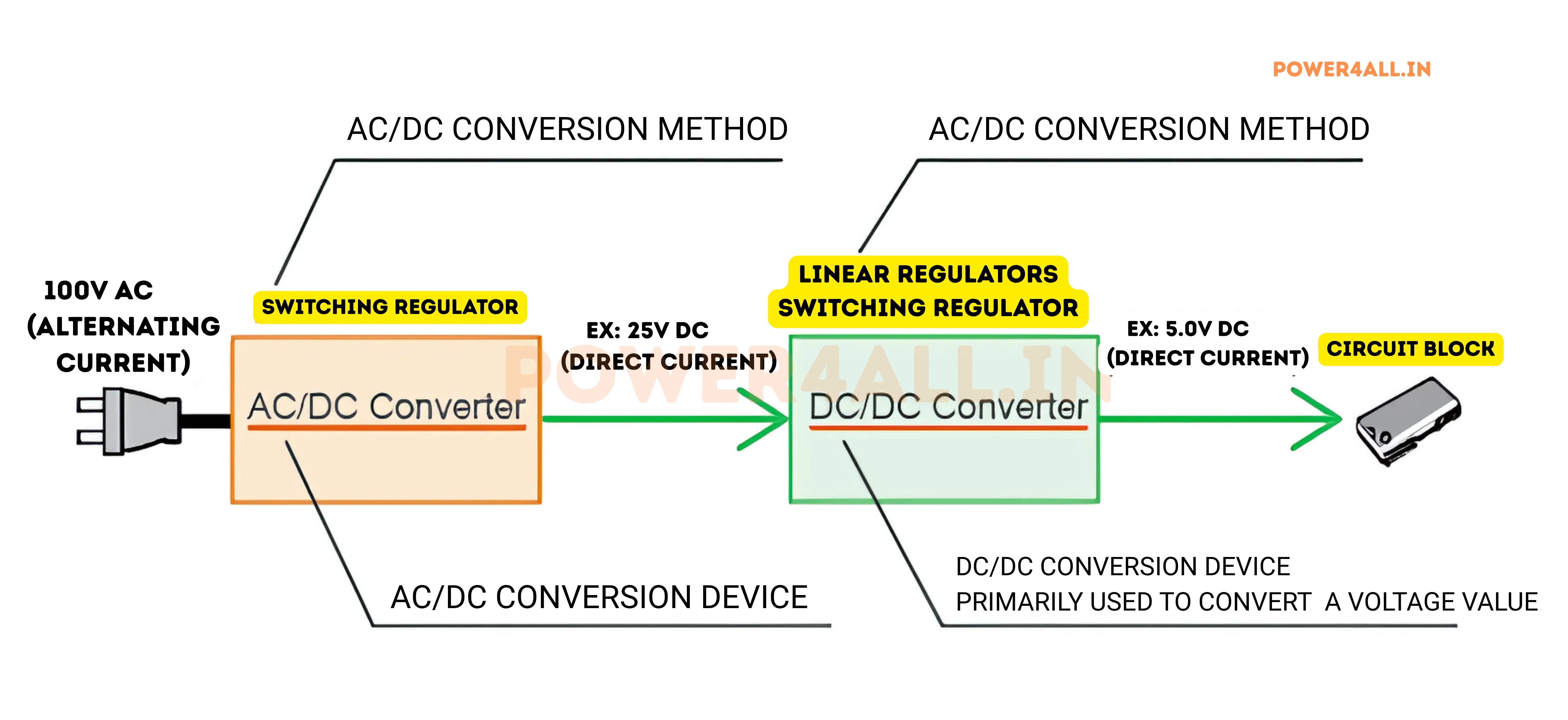
DC-DC converters are vital electronic circuits in modern power management systems. Their main job is to change the voltage of a direct current (DC) source from one level to another. This ensures that electronic devices and systems receive a stable and efficient supply of power.
In many applications, input voltage levels can change, for example, as a battery discharges or when the load on the system varies. DC-DC converters help maintain a constant output voltage, providing reliable power. A key benefit of DC-DC converters, especially switching types, is their high power conversion efficiency. They use switching techniques to minimize energy loss, which is common in other components like linear regulators that often generate heat and waste energy. This efficiency leads to better overall performance and longer battery life in portable devices.
Furthermore, DC-DC converters can step voltage up or down, allowing for flexible power distribution. Some can also provide galvanic isolation, which separates the input and output grounds. This separation reduces the risk of ground loops and protects sensitive components from voltage spikes and noise. Many converters also offer precise voltage regulation, sometimes maintaining output voltage accuracy within a 1% deviation, which is critical for the proper functioning of sensitive electronic systems.
What is a DC-DC Converter?
A DC-DC converter is a power electronics circuit that changes one DC voltage level to another. Unlike transformers, which can only work with AC voltages, DC-DC converters are specifically designed to work with direct current. They can either step up (increase) or step down (decrease) the voltage level depending on the application requirements.
These converters operate on the principle of storing energy temporarily and then releasing it at a different voltage level. This energy storage typically happens in components like inductors and capacitors. Modern DC-DC converters use semiconductor switches (like MOSFETs or IGBTs) that rapidly turn on and off at high frequencies, allowing for efficient power conversion with minimal losses.
DC-DC converters can be broadly classified into two categories:
- Linear Regulators: These use a resistive voltage drop to reduce voltage, simple but less efficient.
- Switching Converters: These use switching elements and energy storage components for higher efficiency.
Switching converters are much more common in modern applications due to their higher efficiency, which can often exceed 90%. This efficiency is particularly important in battery-powered devices where energy conservation directly impacts operating time.
How DC-DC Converters Work?
The operation of DC-DC converters relies on rapidly switching power semiconductor devices, energy storage elements, and control circuits. Let's explore the fundamental working principles:
Basic Operating Principle
Most switching DC-DC converters operate by controlling the duty cycle (on-time vs. off-time ratio) of a semiconductor switch. This switch, typically a MOSFET or IGBT, rapidly turns on and off at frequencies ranging from tens of kilohertz to several megahertz. During the on-time, energy is stored in an inductor or capacitor. During the off-time, this stored energy is transferred to the output at a different voltage level.
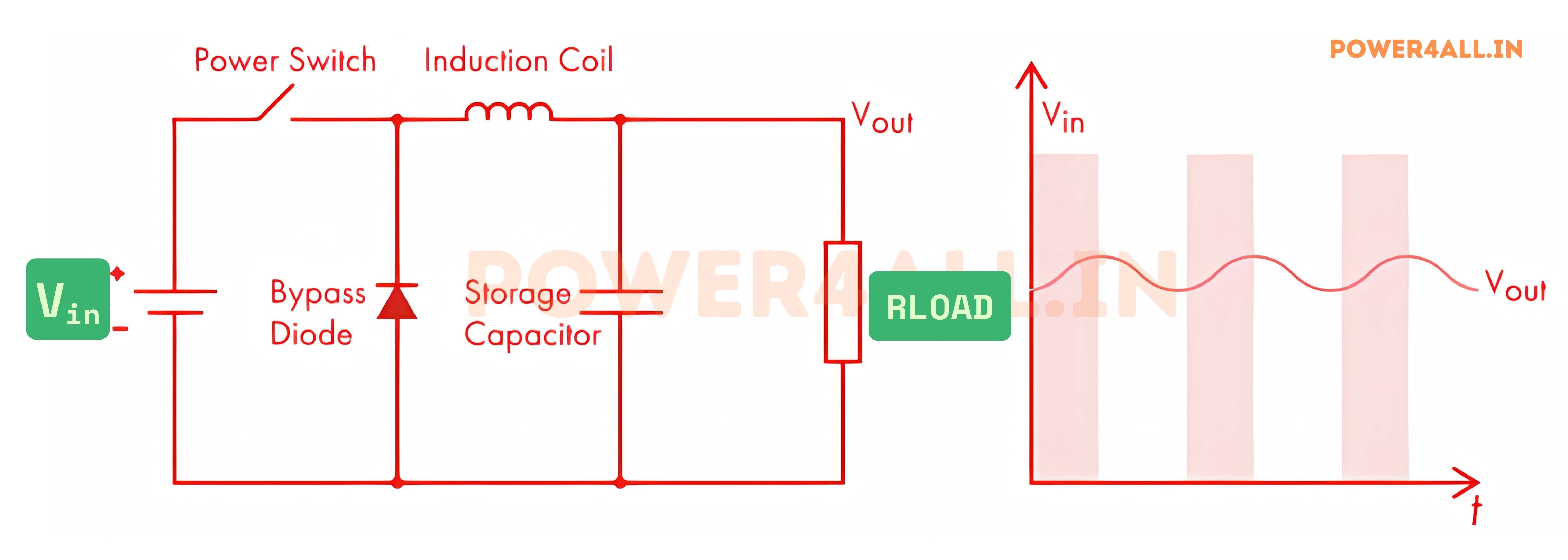
Key Components
A typical switching DC-DC converter consists of:
- Power Switches: MOSFETs or IGBTs that control the flow of current
- Inductors: Store energy in their magnetic field during switching cycles
- Capacitors: Filter the output voltage and reduce ripple
- Diodes: Provide paths for current flow during different switching states
- Control Circuit: Regulates the switching to maintain desired output voltage
Continuous vs. Discontinuous Conduction Mode
DC-DC converters can operate in two main modes:
Continuous Conduction Mode (CCM): The current through the inductor never falls to zero during a switching cycle. This mode is typically used in higher power applications and offers better efficiency.
Discontinuous Conduction Mode (DCM): The inductor current falls to zero for a portion of each switching cycle. This mode is common in light-load conditions and simplifies some aspects of converter design.
Control Methods
To maintain a stable output voltage despite variations in input voltage or load current, DC-DC converters employ feedback control systems. The most common control methods include:
- Pulse Width Modulation (PWM): Adjusts the duty cycle while maintaining a constant switching frequency
- Pulse Frequency Modulation (PFM): Varies the switching frequency to improve efficiency at light loads
- Hysteretic Control: Switches based on upper and lower voltage thresholds for fast transient response
Different Types of DC-DC Converters
DC-DC converters come in various configurations, each designed for specific applications and requirements. They can be broadly categorized into non-isolated and isolated types, with further subdivisions based on their topology and functionality.
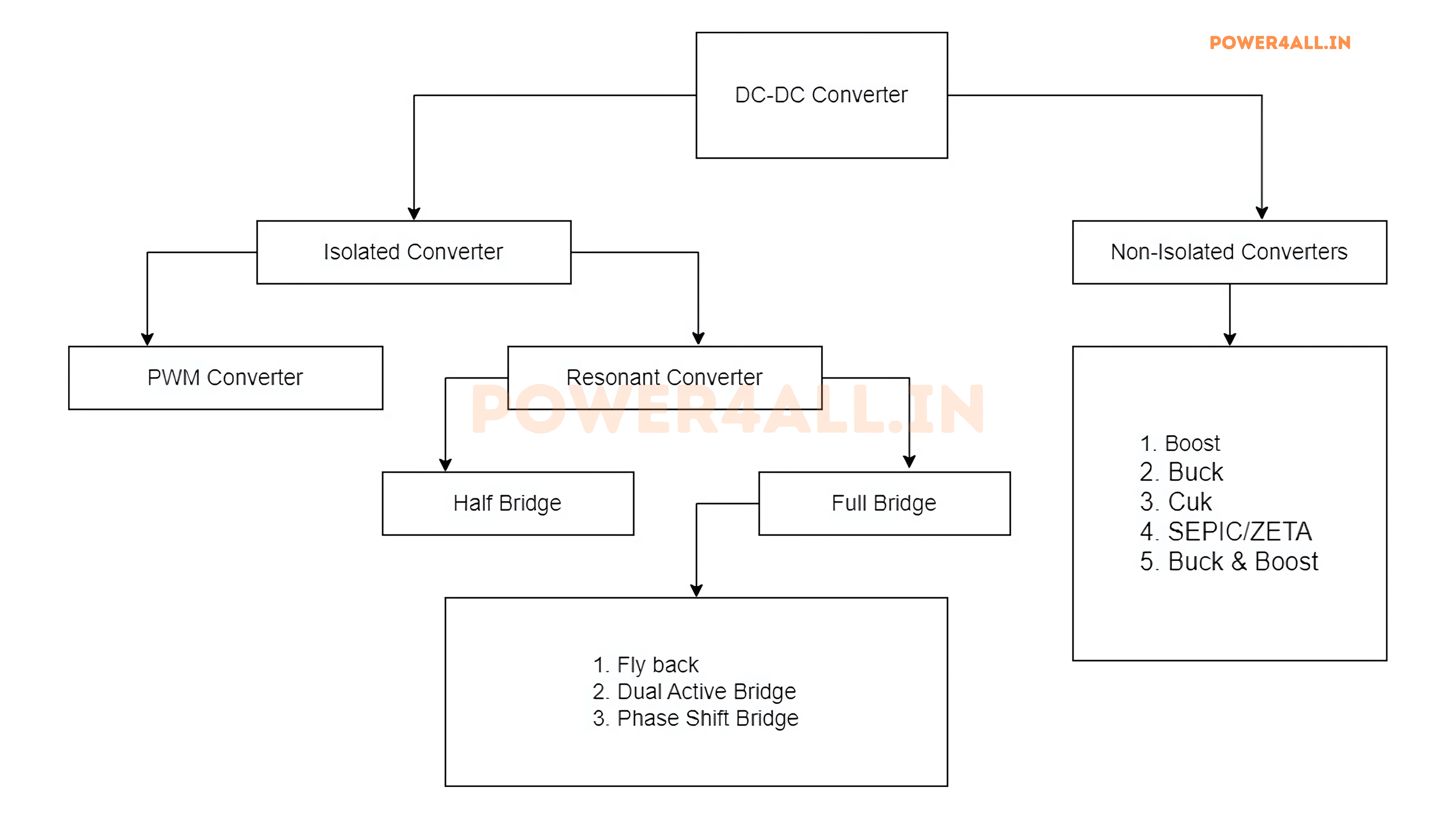
The choice of converter topology depends on factors like input and output voltage requirements, load current, efficiency, size constraints, and whether electrical isolation is needed.
Below are some common types of DC-DC converters:
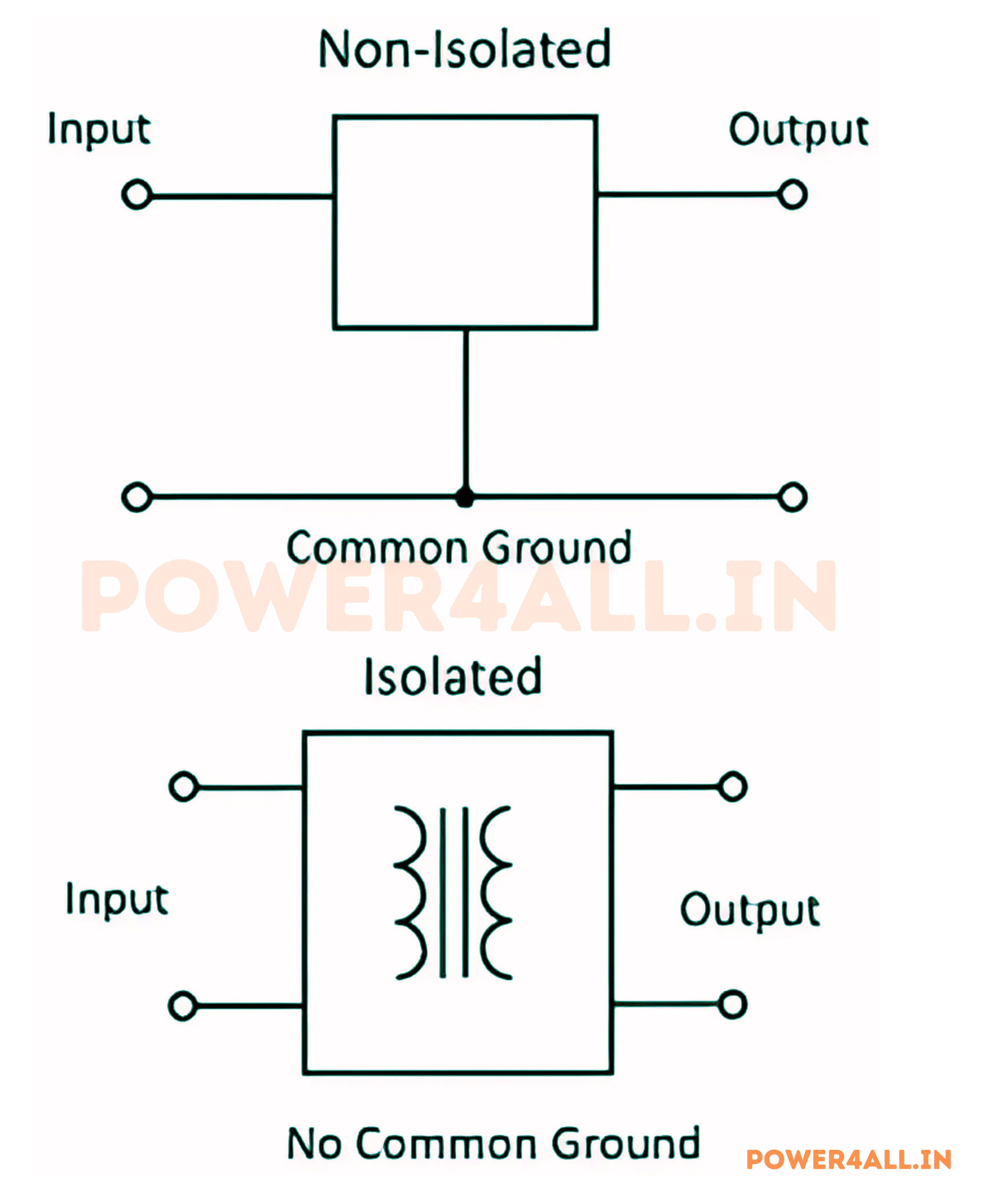
Non-Isolated Converters
Non-isolated converters have a direct electrical connection between input and output. They are simpler, more efficient, and more compact than isolated converters, making them ideal for applications where electrical isolation isn't required.
Buck Converter (Step-Down)
A buck converter reduces the input voltage to a lower output voltage. It consists of a switch (typically a MOSFET), a diode, an inductor, and a capacitor. When the switch is on, the inductor stores energy and charges the capacitor. When the switch is off, the inductor releases its stored energy to maintain current flow.
Buck converters are highly efficient (often exceeding 90%) and are commonly used in applications like voltage regulators in computers, mobile phones, and other portable devices where battery life is critical.
Boost Converter (Step-Up)
A boost converter increases the input voltage to a higher output voltage. It also uses a switch, diode, inductor, and capacitor, but in a different configuration. When the switch is on, current flows through the inductor, storing energy. When the switch turns off, the inductor's collapsing magnetic field generates a voltage that adds to the input voltage, producing a higher output voltage.
Boost converters are used in applications requiring higher voltages than the available source, such as LED drivers, flash circuits in cameras, and voltage boosters for solar panels.
Buck-Boost Converter
A buck-boost converter can either increase or decrease the input voltage, providing flexibility when the input voltage may vary above or below the desired output voltage. It combines features of both buck and boost converters but produces an output voltage with opposite polarity to the input.
These converters are useful in battery-powered systems where the battery voltage drops as it discharges, but a stable output voltage is still required.
Ćuk Converter
The Ćuk converter (named after its inventor, Slobodan Ćuk) can also step voltage up or down but uses a capacitor as the main energy storage element instead of an inductor. It provides an inverted output voltage and offers advantages like continuous input and output currents, which reduce electromagnetic interference (EMI).
Ćuk converters are used in applications requiring low noise and ripple, such as sensitive audio equipment and medical devices.
SEPIC Converter
The SEPIC (Single-Ended Primary Inductor Converter) converter is similar to the Ćuk converter but can provide a non-inverted output voltage. It uses two inductors and a capacitor to achieve this. SEPIC converters can step up or down the input voltage while maintaining the same polarity.
SEPIC converters are often used in applications where the input voltage can vary widely, such as in battery-powered devices and renewable energy systems.
Zeta Converter
The Zeta converter is a type of DC-DC converter that can step up or step down the input voltage while maintaining the same polarity. It uses a combination of inductors and capacitors to achieve this and is known for its ability to provide a stable output voltage even with varying input conditions.
Zeta converters are used in applications where the input voltage can vary widely, such as in battery-powered devices and renewable energy systems.
Isolated Converters
Isolated converters use a transformer to provide electrical isolation between the input and output circuits. This isolation is crucial for safety in certain applications and for preventing ground loops in complex systems.
Flyback Converter
The flyback converter is one of the simplest isolated converters. It uses a transformer with an air gap to store energy when the switch is on and transfer it to the output when the switch is off. It's essentially an isolated version of the buck-boost converter.
Flyback converters are commonly used in low to medium power applications like laptop and phone chargers, LED drivers, and auxiliary power supplies in various electronic equipment.
Forward Converter
The forward converter transfers energy to the output when the switch is on, unlike the flyback converter which transfers energy when the switch is off. It requires a reset mechanism for the transformer core to prevent saturation.
Forward converters are more efficient than flyback converters at higher power levels and are used in applications like computer power supplies and industrial power systems.
Push-Pull Converter
The push-pull converter uses two switches and a center-tapped transformer to efficiently transfer energy. The switches operate alternately, each driving current through half of the primary winding in opposite directions.
Push-pull converters are used in medium to high power applications where high efficiency is required, such as server power supplies and renewable energy systems.
Half-Bridge and Full-Bridge Converters
Half-bridge and full-bridge converters use two or four switches respectively to drive a transformer. They are more complex but offer higher efficiency and power handling capability than simpler topologies.
These converters are used in high-power applications like uninterruptible power supplies (UPS), electric vehicle chargers, and industrial power systems where efficiency and reliability are critical.
Key Characteristics
- Efficiency: Switching converters are highly efficient, often above 85%, minimizing heat and maximizing battery life.
- Voltage Regulation: Maintains output voltage within a tight range, even if the input voltage or load changes.
- Size and Weight: Modern converters are compact and lightweight, ideal for portable and embedded systems.
- Galvanic Isolation: Some converters provide electrical separation between input and output for safety.
- EMC and Thermal Management: Proper design is essential to minimize electromagnetic interference and manage heat.
Advantages of DC-DC Converters
DC-DC converters offer several advantages that make them essential in modern electronic systems:
- High Efficiency: Switching converters can achieve efficiencies greater than 90%, reducing energy loss and heat generation.
- Compact Size: Their small form factor makes them suitable for space-constrained applications.
- Wide Input Voltage Range: Many converters can operate over a broad range of input voltages, making them versatile.
- Low Ripple Voltage: They provide stable output voltage with minimal ripple, essential for sensitive electronics.
- Flexibility: Different topologies allow for various voltage conversion needs, from step-up to step-down and isolated applications.
Disadvantages of DC-DC Converters
While DC-DC converters have many advantages, they also come with some disadvantages:
- Complexity: Switching converters are more complex than linear regulators, requiring careful design and layout.
- EMI Generation: The rapid switching can generate electromagnetic interference (EMI), which may require additional filtering.
- Cost: They can be more expensive than linear regulators, especially in low-power applications.
- Control Circuitry: Requires additional components for feedback and control, increasing the overall circuit complexity.
Applications of DC-DC Converters
DC-DC converters are essential components in numerous applications across various industries. Here are some key applications:
Consumer Electronics
- Smartphones and Tablets: Multiple DC-DC converters manage power from the battery to different components like the processor, display, and wireless modules.
- Laptops and Computers: Convert the main power supply voltage to various levels needed by different components.
- Digital Cameras: Provide stable power for sensors, processors, and displays from battery sources.
Automotive Electronics
- Electric Vehicles: High-power DC-DC converters manage power between batteries, motors, and auxiliary systems.
- Conventional Vehicles: Convert the 12V battery voltage to power various electronic systems like infotainment, lighting, and engine control units.
- Start-Stop Systems: Maintain stable voltage during engine restart operations.
Renewable Energy Systems
- Solar Power Systems: Maximum Power Point Tracking (MPPT) converters optimize energy harvest from solar panels.
- Wind Energy: Convert variable voltage from generators to stable DC for battery charging or grid connection.
- Energy Storage: Manage charging and discharging of battery banks at optimal voltage levels.
Industrial Applications
- Factory Automation: Power sensors, controllers, and communication systems in industrial environments.
- Motor Drives: Provide controlled power to variable speed drives and servo systems.
- Uninterruptible Power Supplies: Convert battery voltage to stable output during power outages.
Telecommunications
- Base Stations: Convert main power to various voltages needed by transmitters, receivers, and digital systems.
- Network Equipment: Power routers, switches, and servers with precise voltage regulation.
- Satellite Systems: Provide efficient power conversion in space-constrained, high-reliability applications.
Medical Devices
- Portable Medical Equipment: Maximize battery life while providing stable power for sensitive instruments.
- Implantable Devices: Ultra-efficient converters for pacemakers and other implants.
- Diagnostic Equipment: Provide isolated power for patient safety in medical instruments.
IoT and Wearable Devices
- Smart Watches: Tiny, efficient converters that maximize battery life.
- Wireless Sensors: Low-power converters for energy harvesting applications.
- Smart Home Devices: Power management for always-on, connected devices.