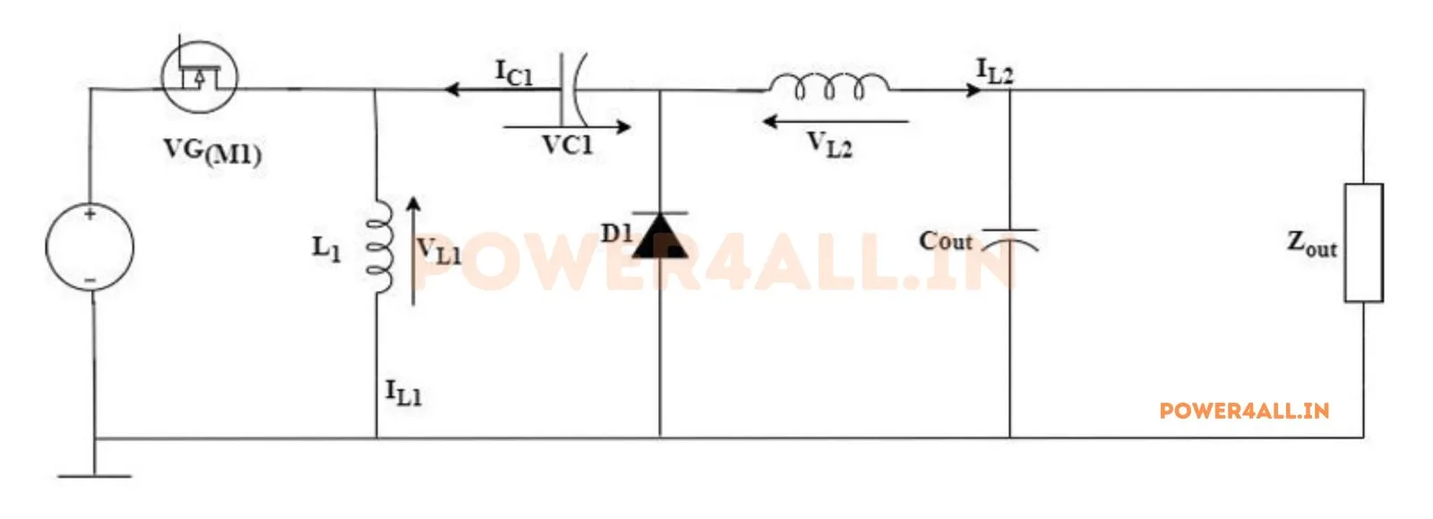
What is a ZETA converter?
The ZETA converter is a DC-DC converter that produces a non-inverting (positive) output that can be higher or lower than the input. It uses two inductors and a series coupling capacitor C₁, and is essentially the mirror image of the SEPIC: where the SEPIC puts its inductor in series with the source for low input ripple, the ZETA puts its output inductor L₂ in series with the load, giving low output current ripple.
How it works — the two switching states
- Switch ON (0 → D·T): the MOSFET connects the input to the circuit; L₁ charges from Vin and energy flows through the coupling capacitor to L₂ and the output. The diode is off.
- Switch OFF (D·T → T): the diode conducts; L₁ transfers its energy to C₁ while L₂ maintains the smooth output current. Volt-second balance sets the ratio.
Key equations
This simulator numerically integrates the full 4th-order switching circuit (two inductors, two capacitors) with your device parasitics to steady state, then measures Vo, the coupling-cap voltage, the ripple and the losses from the resulting waveforms and compares them to the equations above.
ZETA vs SEPIC vs Ćuk
All three give a step-up/step-down ratio of D/(1 − D). The Ćuk is inverting with low ripple on both ports; the SEPIC is non-inverting with low input ripple; the ZETA is non-inverting with low output ripple (its output inductor faces the load). Choose the ZETA when a clean, low-ripple positive output matters most.
| Converter | Polarity | Ideal Vo | Ripple |
|---|---|---|---|
| Ćuk | Inverting (−) | −D·Vin/(1−D) | Low in & out |
| SEPIC | Non-inverting (+) | D·Vin/(1−D) | Low input |
| ZETA | Non-inverting (+) | D·Vin/(1−D) | Low output |
See the Ćuk and SEPIC simulators for the related topologies.
Applications
Battery-to-rail supplies needing a positive, low-ripple output above or below the source — LED drivers, sensor and RF supplies, and automotive/portable electronics where the input voltage crosses the output during discharge.
Frequently asked questions
What is the output voltage of a ZETA converter?
In CCM the ideal output is Vo = D·Vin/(1 − D) — positive (non-inverting), step-down for D < 0.5 and step-up for D > 0.5.
What is the difference between ZETA and SEPIC?
Same conversion ratio, but the ZETA has low output current ripple (output inductor faces the load) while the SEPIC has low input ripple. They are mirror images.
What is the coupling-capacitor voltage?
The average voltage across C₁ equals the output voltage, Vo — the simulator plots it live.
What must the switch and diode withstand?
Both block Vin + Vo.