Complete SCR Silicon Controlled Rectifier Mastery Guide
Master the fundamentals of Silicon Controlled Rectifiers - from basic principles and construction to advanced applications in power control, motor drives, and industrial automation systems
Complete Learning Path - SCR Fundamentals to Applications
Navigate through comprehensive coverage of SCR from basic principles to advanced applications
What is an SCR (Silicon Controlled Rectifier)?
A Silicon Controlled Rectifier (SCR) is a four-layer, three-terminal semiconductor device that acts as an electronically controlled switch for high-power applications. It's part of the thyristor family and can handle hundreds of amperes and thousands of volts, making it essential for industrial power control, motor drives, and AC power regulation.
PNPN Structure = P-N-P-N Layers
Four alternating semiconductor layers create unique switching behavior
Why SCRs are Revolutionary
SCRs revolutionized power electronics by providing a solid-state replacement for mechanical switches and vacuum tubes in high-power applications. Before SCRs, controlling large amounts of power required bulky, slow, and unreliable mechanical contactors or expensive vacuum tubes.
High Power Handling
SCRs can control thousands of watts to megawatts of power, handling currents from amperes to thousands of amperes and voltages up to several kilovolts.
Latching Action
Once triggered ON, the SCR remains conducting without continuous gate signal until the current naturally drops to zero, providing reliable switching.
Fast Switching
SCRs can turn ON in microseconds, enabling precise control of AC power and high-frequency switching applications.
Robust & Reliable
No moving parts, immune to vibration and shock, with lifespans measured in decades when properly applied.
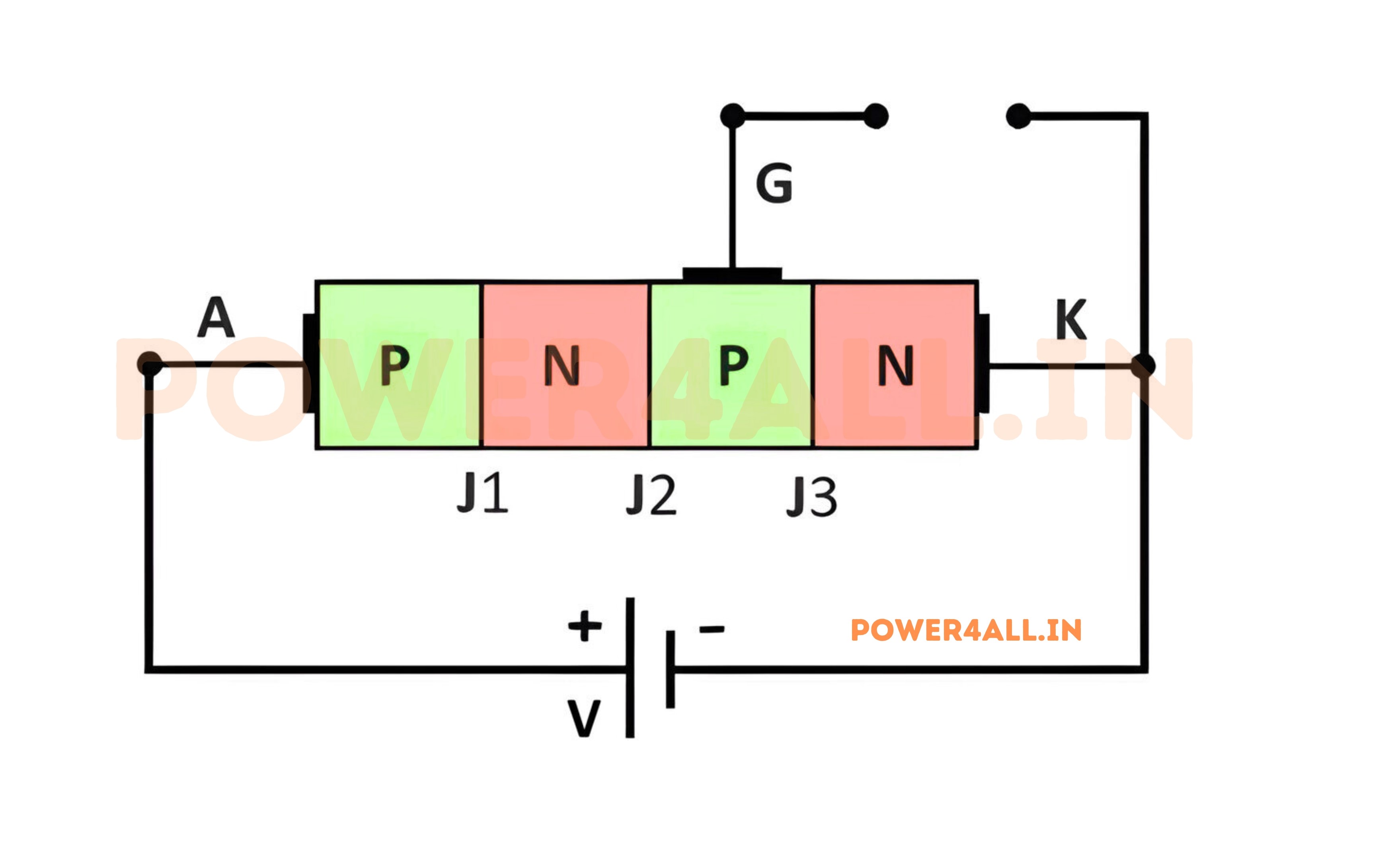
SCR Terminals and Symbol
Three Terminals
- Anode (A): Positive terminal, current flows IN when conducting
- Cathode (K): Negative terminal, current flows OUT
- Gate (G): Control terminal, small trigger signal turns SCR ON
- Symbol: Diode symbol with additional gate terminal
- Current flow: Anode to Cathode when triggered
Operating Principle
- OFF state: No current flows despite forward voltage
- Trigger: Small gate current pulse turns SCR ON
- ON state: Large current flows, gate loses control
- Turn-off: Current must drop to zero naturally
- Recovery: SCR ready for next trigger cycle
SCR Applications in Everyday Life
- Light dimmers: Control brightness of incandescent and halogen lights
- Motor drives: Speed control for industrial motors and appliances
- Welding machines: Control welding current for consistent arc quality
- Battery chargers: Regulate charging current and voltage
- Power supplies: Switching and regulation in DC power supplies
- Heating controls: Temperature regulation in industrial ovens
Historical Impact
The SCR was invented at Bell Labs in 1956 by a team led by Gordon Hall. This breakthrough enabled the development of modern power electronics, making possible everything from efficient motor drives to high-voltage DC transmission systems. Today, SCRs and related thyristors control most of the world's electrical power!
SCR Fundamentals & Physics of Operation
Understanding SCR operation requires exploring the four-layer PNPN structure, junction behavior, and the regenerative feedback mechanism that creates the unique latching characteristic. This physics foundation explains why SCRs are so effective for power control applications.
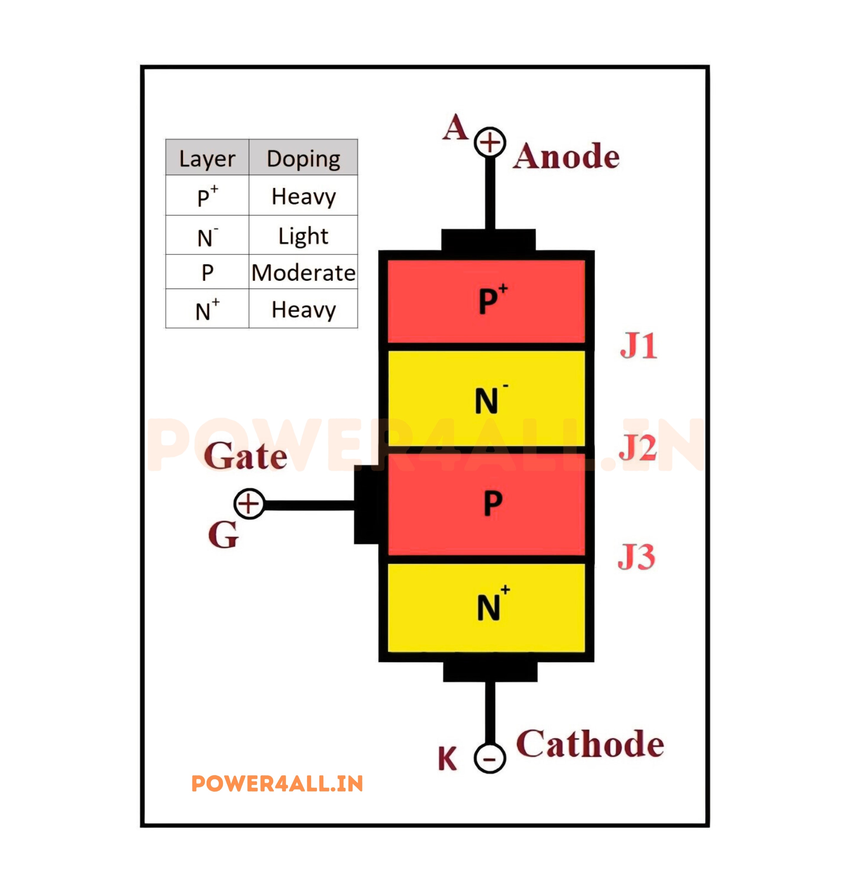
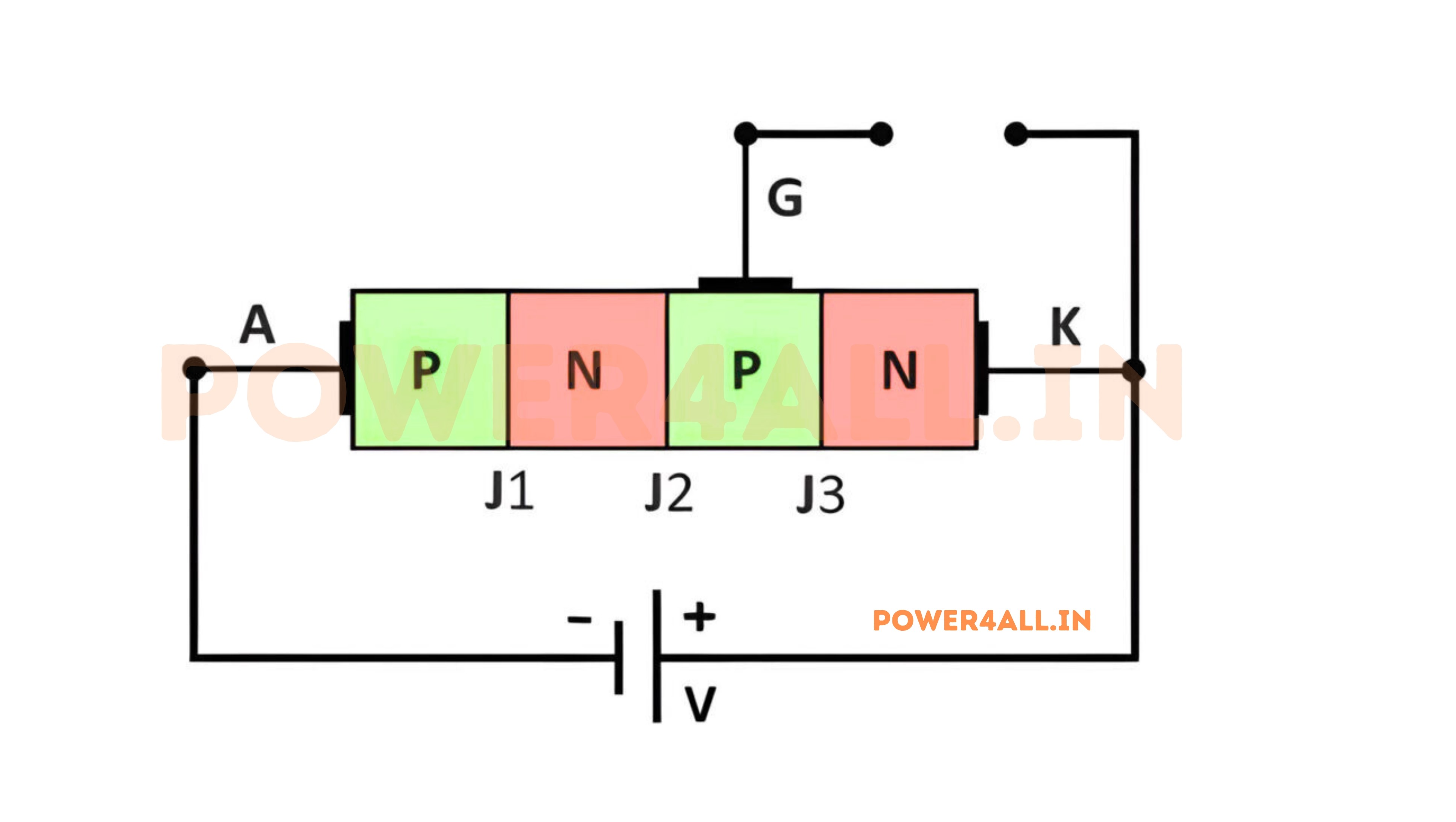
Four-Layer PNPN Structure
Understanding the PNPN Semiconductor Structure
Layer Construction
An SCR consists of four alternating layers of P-type and N-type semiconductor material, creating three P-N junctions. This unique structure enables the characteristic switching behavior.
| Layer | Type | Function | Doping Level |
|---|---|---|---|
| P1 (Anode) | P-type | Current injection | Heavy (P+) |
| N1 | N-type | Base of PNP transistor | Light (N-) |
| P2 (Base) | P-type | Base of NPN transistor | Light (P-) |
| N2 (Cathode) | N-type | Current collection | Heavy (N+) |
Junction Behavior
J1 Junction (P1-N1)
Forward biased in normal operation, injects holes from anode region into N1 base.
J2 Junction (N1-P2)
Reverse biased initially, blocks current flow until regenerative action begins.
J3 Junction (P2-N2)
Forward biased in normal operation, connected to gate for triggering control.
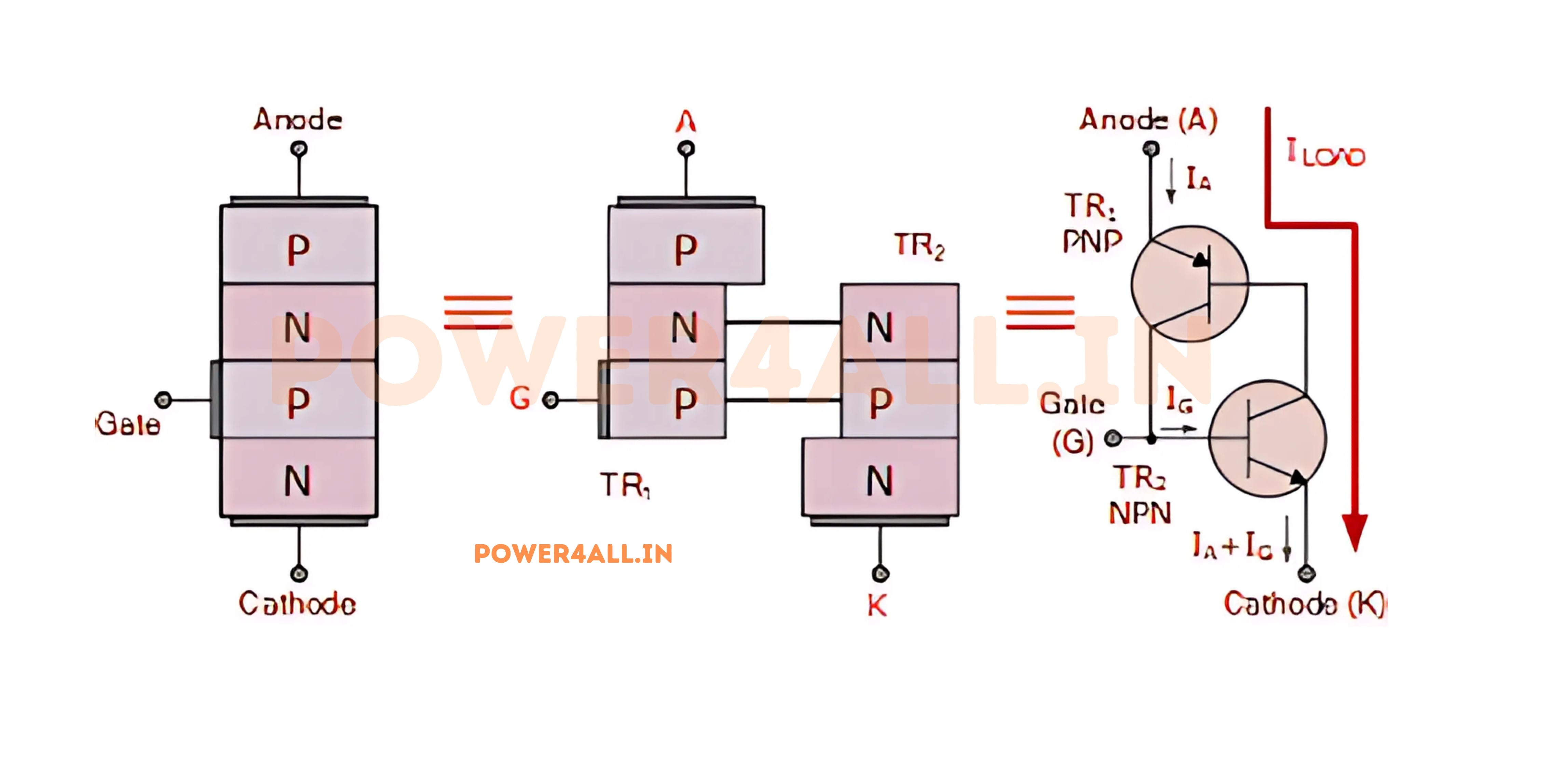
Two-Transistor Model
Equivalent Circuit
The SCR can be understood as two interconnected transistors - a PNP and an NPN transistor with positive feedback that creates the latching behavior.
Transistor Configuration
- PNP transistor: P1-N1-P2 (collector-base-emitter)
- NPN transistor: N1-P2-N2 (collector-base-emitter)
- Feedback loop: Collector of each feeds base of other
- Gate connection: Base of NPN transistor (P2 layer)
α1 + α2 ≥ 1
Condition for SCR turn-on (α = current gain)
Regenerative Process
- Step 1: Gate current starts NPN conduction
- Step 2: NPN collector current becomes PNP base current
- Step 3: PNP collector current reinforces NPN base current
- Step 4: Positive feedback rapidly increases both currents
- Result: Both transistors saturate, SCR turns fully ON
Turn-On Mechanism
Gate Triggering Process
How small gate current triggers large anode current
Critical Parameters
Key values that determine SCR behavior
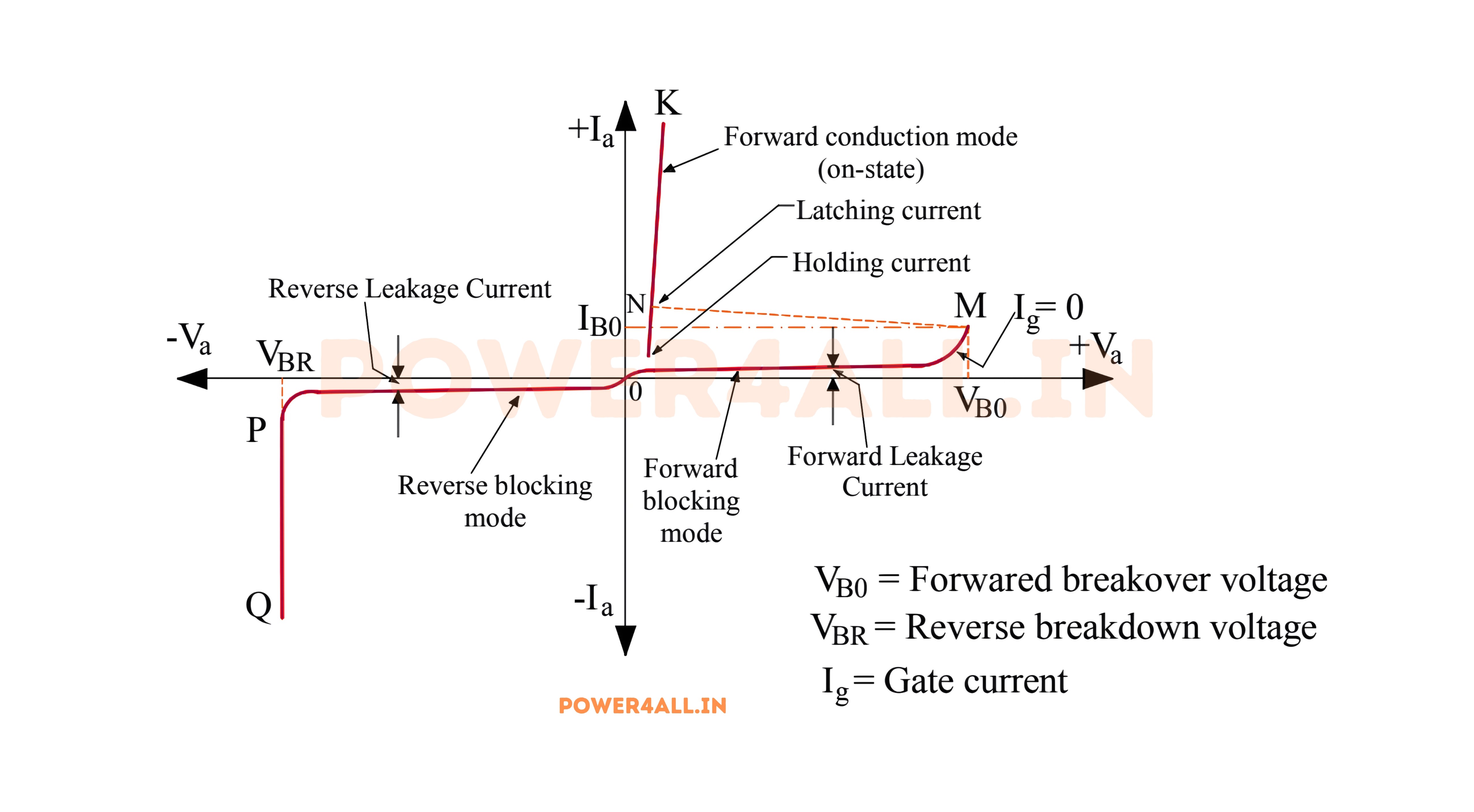
Turn-On Requirements
- Gate trigger current (IGT): Minimum gate current for turn-on
- Gate trigger voltage (VGT): Minimum gate voltage for turn-on
- Latching current (IL): Minimum anode current to maintain conduction
- Holding current (IH): Minimum current to prevent turn-off
IGT = 1mA to 200mA
Typical gate trigger current range
Turn-Off Mechanism
How SCRs Turn OFF - Commutation Process
Unlike turn-on which is controlled by the gate, SCR turn-off is controlled by the anode-cathode circuit. The SCR cannot be turned off by the gate once it's conducting.
Natural Commutation (AC Circuits)
Current Zero Crossing
In AC circuits, SCR automatically turns off when AC current naturally reaches zero at the end of each half-cycle.
Recovery Time
After turn-off, SCR needs recovery time before it can block forward voltage again. This is called turn-off time (tq).
Forced Commutation (DC Circuits)
In DC circuits, external circuitry must force the current to zero:
- Capacitor commutation: Pre-charged capacitor reverses current
- Inductor commutation: Inductor diverts current to alternate path
- Auxiliary SCR: Second SCR diverts main current
- Transistor commutation: Power transistor short-circuits SCR
Gate Control Limitation
Once an SCR is conducting, the gate completely loses control. Applying negative gate voltage or removing gate current will NOT turn off the SCR. This is fundamentally different from transistors and is a key characteristic of thyristor operation.
SCR Construction & Physical Structure
SCR construction varies significantly with power rating and application. From small signal SCRs in TO-92 packages to massive industrial SCRs in hockey puck or press-pack formats, the physical design directly impacts electrical performance, thermal management, and reliability.
Silicon Wafer Fabrication
PNPN Layer Creation
SCRs start with high-purity silicon wafers where the four alternating layers are created through precise doping and diffusion processes. The thickness and doping concentrations determine the voltage and current ratings.
Layer Specifications
- Total thickness: 50μm (low voltage) to 500μm (high voltage)
- P1 (anode): 10-50μm thick, 10¹⁸-10¹⁹ atoms/cm³
- N1 layer: 20-200μm thick, 10¹⁴-10¹⁵ atoms/cm³
- P2 (base): 10-100μm thick, 10¹⁵-10¹⁶ atoms/cm³
- N2 (cathode): 5-20μm thick, 10¹⁸-10¹⁹ atoms/cm³
Package Types and Applications
Low Power SCRs
Small signal and logic level applications
Package Types
- TO-92: 0.5A-2A, plastic package, through-hole
- SOT-23: 0.1A-1A, surface mount, compact size
- TO-126: 1A-4A, metal tab for heat sinking
- TO-220: 4A-25A, bolt-on heat sink mounting
Applications
- Power supplies and chargers
- Light dimmers and controllers
- Motor speed controls
- Temperature controllers
- Crowbar protection circuits
Medium Power SCRs
Industrial control and power conversion
Package Types
- TO-247: 25A-50A, through-hole with heat sink tab
- TO-264: 50A-100A, enhanced thermal performance
- ITO-220: Isolated tab versions for safety
- D2PAK: Surface mount power packages
Applications
- Motor drives and controls
- Welding equipment
- UPS systems
- Battery chargers
- Heating controls
High Power SCRs
Industrial and utility applications
Package Types
- Hockey Puck: 100A-5000A, dual-sided cooling
- Press Pack: 1000A-8000A, pressure contact
- Stud Mount: 50A-1000A, threaded stud mounting
- Module: Multiple devices in single package
Applications
- HVDC transmission
- Large motor drives
- Smelting furnaces
- Railway traction
- Grid-tie inverters
Thermal Management and Heat Sinking
Critical Thermal Design for SCR Reliability
Power Dissipation in SCRs
SCRs dissipate power primarily during conduction, with additional losses during switching transitions. Proper thermal management is critical for reliability and performance.
| Package Type | Power Rating | Thermal Resistance | Cooling Method | Max Junction Temp |
|---|---|---|---|---|
| TO-92 | 0.5W - 2W | 150°C/W | Natural convection | 125°C |
| TO-220 | 10W - 75W | 3°C/W to case | Heat sink required | 150°C |
| Hockey Puck | 1kW - 50kW | 0.05°C/W to case | Water or forced air | 125-150°C |
| Press Pack | 10kW - 500kW | 0.01°C/W to case | Direct water cooling | 125°C |
Cooling System Design
Heat Sink Selection
Choose heat sink thermal resistance based on power dissipation and ambient temperature. Include thermal interface material for good heat transfer.
Forced Air Cooling
Fans can reduce thermal resistance by 5-10×, enabling higher power operation in smaller packages.
Liquid Cooling
Water or specialized coolants provide the ultimate thermal performance for megawatt-class applications.
Thermal Interface
Thermal grease, pads, or phase-change materials ensure efficient heat transfer from device to heat sink.
TJ = TA + (θJA × PD)
Junction temperature calculation for thermal design
Thermal Design Example
50A SCR in TO-247 package dissipating 100W:
- Junction-to-case: θJC = 0.5°C/W
- Case-to-heat sink: θCS = 0.2°C/W (with thermal compound)
- Heat sink-to-ambient: θSA = 1.0°C/W (with fan)
- Total thermal resistance: θJA = 0.5 + 0.2 + 1.0 = 1.7°C/W
- Junction temperature: TJ = 25°C + (1.7 × 100W) = 195°C (TOO HOT!)
- Solution: Better heat sink with θSA = 0.3°C/W → TJ = 125°C (acceptable)
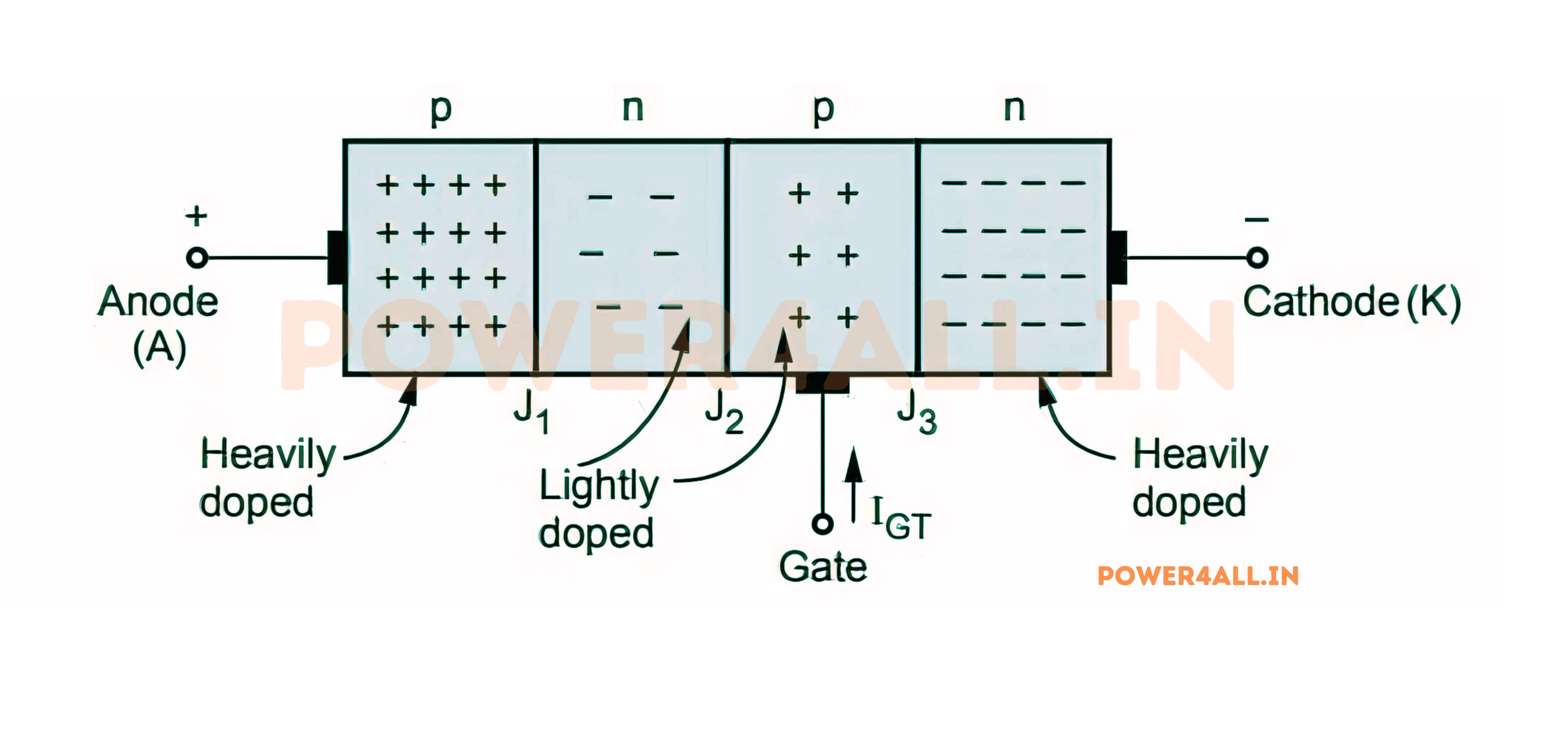
SCR Operating Modes & States
SCRs have distinct operating states determined by the applied voltages and current conditions. Understanding these states - Forward Blocking, Forward Conducting, and Reverse Blocking - is essential for proper circuit design and SCR application.
Forward Blocking State (OFF)
Blocking Characteristics
SCR blocks forward voltage until triggered
Operating Conditions
- Anode positive: VAK > 0 (forward biased)
- Gate signal: No gate current or insufficient trigger
- Current flow: Only tiny leakage current (μA range)
- Voltage drop: Nearly full applied voltage across SCR
- Power dissipation: Very low (V × I_leakage)
I_leakage < 10mA
Typical forward blocking current
Breakover Voltage
Maximum voltage SCR can block
Breakover Characteristics
- VBO (breakover voltage): SCR turns on without gate signal
- Avalanche breakdown: Uncontrolled turn-on mechanism
- Typical values: 50V to 8000V depending on rating
- Design margin: Never operate near breakover voltage
- Temperature effect: VBO decreases with temperature
Breakover Warning
Operating near breakover voltage can cause unpredictable turn-on and potential device damage. Always maintain adequate safety margin (typically 80% of VBO maximum).
Reverse Blocking State
SCR Behavior Under Reverse Voltage
Reverse Voltage Operation
When the anode is negative relative to the cathode, the SCR blocks current flow in the reverse direction, similar to a reverse-biased diode.
Reverse Breakdown
Maximum reverse voltage the SCR can withstand before breakdown occurs, typically lower than forward breakover voltage.
Leakage Current
Small reverse current flows (microamps), increasing with temperature and approaching reverse breakdown voltage.
| Parameter | Symbol | Typical Range | Description |
|---|---|---|---|
| Reverse Breakdown Voltage | VRRM | 50V - 6000V | Maximum safe reverse voltage |
| Reverse Leakage Current | IRRM | 1µA - 100µA | Current at rated reverse voltage |
| Reverse Recovery Time | trr | 1µs - 100µs | Time to block reverse voltage |
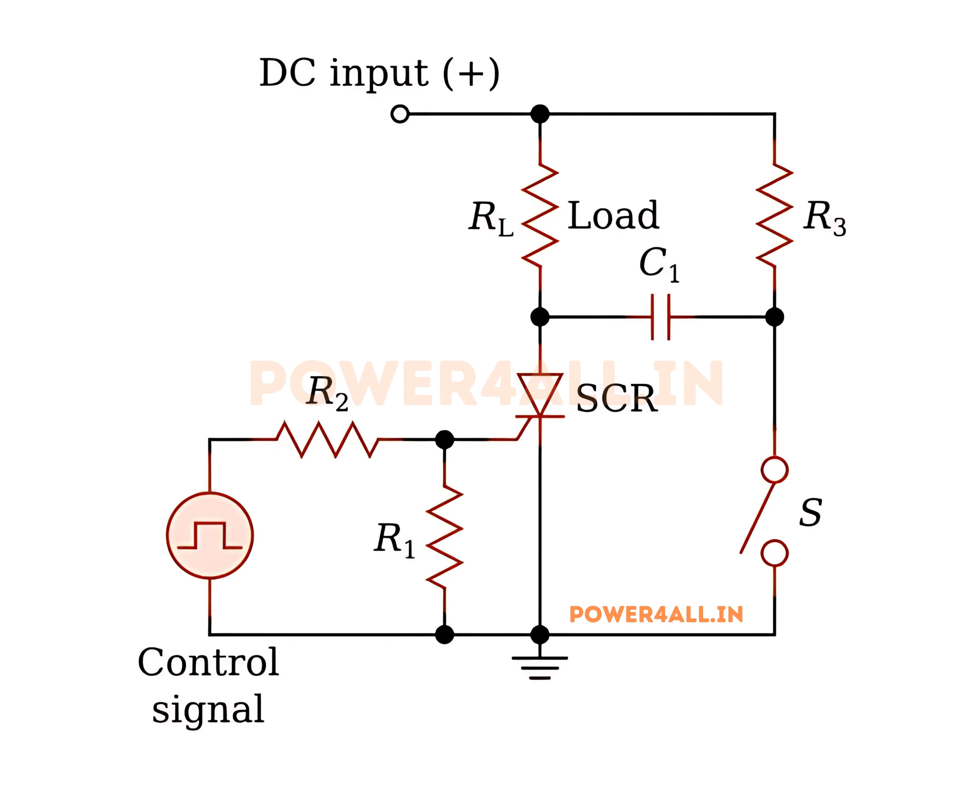
SCR Triggering Methods
SCRs can be triggered into conduction through various methods, each suitable for different applications. Understanding these triggering techniques is essential for designing reliable SCR control circuits and achieving precise switching control.
Gate Current Triggering
Most Common Triggering Method
Controlled turn-on using gate current pulse
Basic Requirements
- Gate trigger current (IGT): Minimum current to turn on SCR
- Gate trigger voltage (VGT): Minimum voltage across gate-cathode
- Pulse duration: Must be long enough for anode current to build up
- Current rise rate: Adequate di/dt for reliable triggering
Typical Gate Specifications
- IGT: 1mA - 200mA (depending on SCR size)
- VGT: 0.7V - 2.5V (similar to diode drop)
- Pulse width: 10µs minimum typical
- Peak gate current: 1A - 10A for fast turn-on
Gate Drive Circuits
Practical circuits for reliable gate triggering
Simple Resistive Drive
- Gate resistor: Limits gate current to safe value
- Pull-down resistor: Ensures gate is off when not triggered
- Calculation: RG = (VCC - VGT) / IGT
- Applications: Simple on/off control
Pulse Transformer Drive
- Isolation: Electrical isolation between control and power
- Multiple SCRs: Can drive several SCRs simultaneously
- High voltage: Safe control of high-voltage SCRs
- Fast switching: Sharp current pulses for reliable triggering
Optocoupler Drive
- Optical isolation: Complete electrical isolation
- Noise immunity: Immune to electrical interference
- Low power: Can be driven directly from logic circuits
- Safety: Protects control circuits from power surges
Alternative Triggering Methods
Temperature Triggering
Thermal activation for protection circuits
Operating Principle
- Leakage current: Increases exponentially with temperature
- Thermal feedback: Higher current creates more heat
- Trigger temperature: SCR turns on at specific temperature
- Applications: Thermal protection and temperature sensing
I = I₀ × e^(T/T₀)
Exponential increase of leakage with temperature
Light Triggering (LASCR)
Optical triggering for isolation and control
Light-Activated SCR Features
- Optical window: Transparent section in package
- Light sensitivity: Infrared to visible light spectrum
- Isolation: Complete electrical isolation
- EMI immunity: Immune to electromagnetic interference
Applications
- High voltage isolation: Safe control of high-voltage circuits
- Remote control: Optical fiber control systems
- Light sensors: Automatic lighting controls
- Safety systems: Explosion-proof environments
dv/dt Triggering
Unwanted triggering by rapid voltage changes
Mechanism
- Capacitive coupling: Junction capacitance couples voltage changes
- Critical dv/dt: Rate above which false triggering occurs
- Snubber circuits: RC networks to limit dv/dt
- Prevention: Proper circuit design prevents false triggering
dv/dt Protection
Always include snubber networks (RC circuits) across SCRs in switching applications to prevent false triggering from rapid voltage changes. Typical values: 0.1µF capacitor with 100Ω resistor.
Phase Control Triggering
Precise AC Power Control Using Phase-Controlled Triggering
Phase control allows precise control of AC power by varying the point in each AC cycle where the SCR is triggered. This enables smooth power control from 0% to nearly 100%.
Phase Control Principle
Firing Angle (α)
The point in the AC cycle where the SCR is triggered, measured from the zero crossing. Controls average power delivered to load.
Conduction Angle
Portion of each half-cycle where SCR conducts. Equals (180° - α) for resistive loads.
Power Control
Average power varies with firing angle: 100% at α=0°, 50% at α=90°, 0% at α=180°.
Phase Control Circuits
Simple RC Phase Control
- RC network: Creates phase shift for trigger timing
- Variable resistor: Adjusts firing angle
- Diac trigger: Provides sharp trigger pulse
- Power range: 10% - 90% typical
- Applications: Light dimmers, motor speed controls
P_avg = P_max × [1 - α/π + sin(2α)/(2π)]
Average power vs firing angle for resistive load
SCR Characteristics & Key Parameters
Understanding SCR electrical characteristics and key parameters is essential for proper device selection and circuit design. These specifications define the limits, performance, and reliability of SCR operation in various applications.
Voltage and Current Ratings
| Parameter | Symbol | Description | Typical Range | Design Considerations |
|---|---|---|---|---|
| Peak Repetitive Forward Voltage | VDRM | Maximum forward blocking voltage | 50V - 8000V | Derate to 80% for safety margin |
| Peak Repetitive Reverse Voltage | VRRM | Maximum reverse blocking voltage | 50V - 6000V | Usually same as VDRM |
| RMS On-State Current | IT(RMS) | Maximum continuous current | 1A - 5000A | Thermal design critical |
| Average On-State Current | IT(AV) | Maximum average current | 0.5A - 3000A | Used for heat sink design |
| Peak Surge Current | ITSM | Short-term overload capability | 10A - 50kA | Protection against transients |
Gate Trigger Parameters
Gate Sensitivity
Parameters defining gate trigger requirements
Key Gate Parameters
- IGT (Gate Trigger Current): Minimum current to turn on SCR
- VGT (Gate Trigger Voltage): Minimum gate-cathode voltage
- IH (Holding Current): Minimum anode current to stay on
- IL (Latching Current): Minimum current to maintain conduction
Gate Drive Design
For reliable triggering:
- Gate current: 3-5× IGT minimum
- Pulse duration: >10µs typical
- Temperature derating: IGT increases at low temperature
- Noise margin: Avoid false triggering
Switching Characteristics
Time-related parameters for switching applications
Turn-On Times
- tgt (Gate-controlled turn-on time): 0.1µs - 10µs
- ton (Turn-on time): Total time to reach full conduction
- di/dt capability: Maximum rate of current rise
- Spread time: Time for conduction to spread across junction
Turn-Off Times
- tq (Turn-off time): Recovery time after current zero
- trr (Reverse recovery time): Time to block reverse voltage
- dv/dt capability: Maximum voltage rise rate when off
di/dt = ΔI / Δt
Rate of current rise limitation
Thermal Characteristics
Temperature Effects and Thermal Management
Critical Thermal Parameters
| Parameter | Symbol | Typical Value | Significance |
|---|---|---|---|
| Junction Temperature | TJ | 125°C - 150°C max | Maximum safe operating temperature |
| Thermal Resistance (Junction to Case) | RθJC | 0.1°C/W - 5°C/W | Heat transfer to package |
| Thermal Resistance (Case to Sink) | RθCS | 0.1°C/W - 0.5°C/W | Interface thermal resistance |
| Storage Temperature | TSTG | -40°C to +150°C | Safe storage range |
Power Dissipation Calculation
PD = VT × IT(AV) + (dv/dt × C × f)
Total power dissipation (conduction + switching losses)
Heat Sink Sizing
Calculate required thermal resistance: RθSA = (TJ_max - TA) / PD - RθJC - RθCS
Cooling Methods
Natural convection, forced air, liquid cooling based on power level and package type.
Dynamic Characteristics
di/dt and dv/dt Ratings
Rate limitations for reliable operation
Current Rate Limitation (di/dt)
- Physical limit: How fast current can spread across junction
- Typical values: 10A/µs to 1000A/µs
- Consequences: Localized heating if exceeded
- Protection: Series inductance limits di/dt
Voltage Rate Limitation (dv/dt)
- False triggering: Rapid voltage rise can turn on SCR
- Typical values: 10V/µs to 1000V/µs
- Mechanism: Capacitive coupling through junctions
- Protection: Snubber circuits (RC networks)
Snubber Circuit Design
RC snubber calculation:
- C = IT² × ton / (2 × V² × dv/dt)
- R = √(L/C) where L is circuit inductance
- Typical values: C = 0.01µF - 1µF, R = 10Ω - 100Ω
Safe Operating Area
Defining safe operating boundaries
SOA Limitations
- Maximum voltage: VDRM at specified temperature
- Maximum current: IT(RMS) with proper cooling
- Power dissipation: Thermal limits determine maximum power
- Surge current: Short-term overload capability
Derating Guidelines
- Voltage derating: Use 80% of VDRM rating
- Current derating: Account for temperature rise
- Temperature derating: Reduce ratings at high temperature
- Safety margin: Conservative design for reliability
Design Best Practices
Always operate SCRs well within their ratings. Use 80% voltage derating, adequate thermal management, proper gate drive, and protection circuits for reliable long-term operation.
SCR Power Control Applications
SCRs excel in power control applications due to their ability to handle high voltages and currents while providing precise control. From simple light dimmers to complex industrial motor drives, SCRs are fundamental to modern power electronics.
AC Motor Speed Control
Single-Phase Motor Control
Variable speed control for single-phase AC motors
Phase Control Method
- Voltage control: Varying RMS voltage controls motor speed
- Speed range: 20% - 95% of synchronous speed
- Applications: Fans, pumps, small industrial motors
- Control circuit: Phase control with feedback
Circuit Configuration
- Back-to-back SCRs: Control both half-cycles
- Snubber circuits: Protect against voltage transients
- Current limiting: Protect motor during startup
- Feedback control: Maintain constant speed under load
Fan Speed Control Example
- Motor: 1HP, 230V single-phase
- SCR rating: 25A, 600V
- Speed range: 300 - 1750 RPM
- Efficiency: 85% at full speed
- Control: Potentiometer or microcontroller
Three-Phase Motor Drives
High-power three-phase motor control systems
Six-SCR Bridge Configuration
- Full control: Six SCRs control all three phases
- Firing sequence: 60° intervals for smooth operation
- Power range: 1kW to 50MW applications
- Efficiency: >95% in large drives
Industrial Applications
- Steel mills: Rolling mill motor drives
- Mining: Conveyor and crusher motors
- Marine: Ship propulsion systems
- Railways: Traction motor control
- Cement plants: Kiln and mill drives
V_dc = 1.35 × V_line × cos(α)
DC voltage output from 3-phase SCR bridge
Heating and Temperature Control
Industrial Heating Control
SCRs provide precise temperature control in industrial heating applications by varying the power delivered to heating elements through phase control or time-proportional control.
Control Methods
- Phase control: Continuous power variation
- Burst firing: On/off control with time proportioning
- Zero-crossing switching: Reduces EMI and harmonics
- PID control: Precise temperature regulation
Furnace Control System
- Application: 500°C heat treatment furnace
- Power: 100kW heating elements
- SCRs: 200A, 1200V three-phase
- Control: Thermocouple feedback
- Accuracy: ±1°C temperature control
- Response time: <30 seconds to setpoint
Heating Applications
Industrial Furnaces
Heat treatment, annealing, and melting furnaces with precise temperature profiles and energy efficiency.
HVAC Systems
Electric heating elements in air handlers, baseboard heaters, and radiant heating systems.
Food Processing
Cooking, baking, and food processing equipment with precise temperature control and energy efficiency.
Chemical Processing
Reactor heating, distillation columns, and process heating with tight temperature control.
Power Supply and Conversion
SCRs in Power Conversion and Supply Systems
Controlled Rectifiers
SCRs enable variable DC output from AC sources, providing both voltage regulation and power factor control in high-power applications.
Battery Chargers
Constant current and constant voltage charging
Charging Profiles
- Constant current: Initial high-rate charging
- Constant voltage: Final charging phase
- Float charging: Maintenance charging
- Temperature compensation: Adjust for battery temperature
Applications
- UPS systems: Backup power battery banks
- Electric vehicles: Fast charging stations
- Telecommunications: -48V battery systems
- Emergency lighting: Building safety systems
Electroplating and Electrolysis
High-current DC power for electrochemical processes
Process Requirements
- High current: 1000A+ for large-scale operations
- Low voltage: 5V-50V typical
- Ripple control: Low ripple for quality plating
- Current regulation: Precise current control
Industrial Uses
- Metal finishing: Chrome, nickel, gold plating
- PCB manufacturing: Copper plating
- Aluminum production: Hall-Héroult process
- Chlorine production: Electrolytic cells
HVDC Transmission
| System Component | SCR Function | Typical Ratings | Applications |
|---|---|---|---|
| Rectifier Station | AC to DC conversion | 4000A, 8000V | Power transmission |
| Inverter Station | DC to AC conversion | 4000A, 8000V | Grid interconnection |
| Voltage Control | DC voltage regulation | Variable firing angle | System stability |
| Power Control | Bidirectional power flow | ±800kV, 3000MW | Grid balancing |
HVDC Link Example
1000MW HVDC transmission line:
- Voltage: ±500kV DC
- Current: 2000A
- SCRs per converter: 72 (12-pulse configuration)
- SCR rating: 4000A, 8500V each
- Distance: 1000km+ transmission capability
- Efficiency: >97% overall efficiency
Phase Control & Dimming Applications
Phase control is one of the most common SCR applications, enabling smooth power control from 0% to nearly 100% by controlling when the SCR turns on during each AC cycle. This technique is widely used in lighting dimmers, motor speed controls, and heating applications.
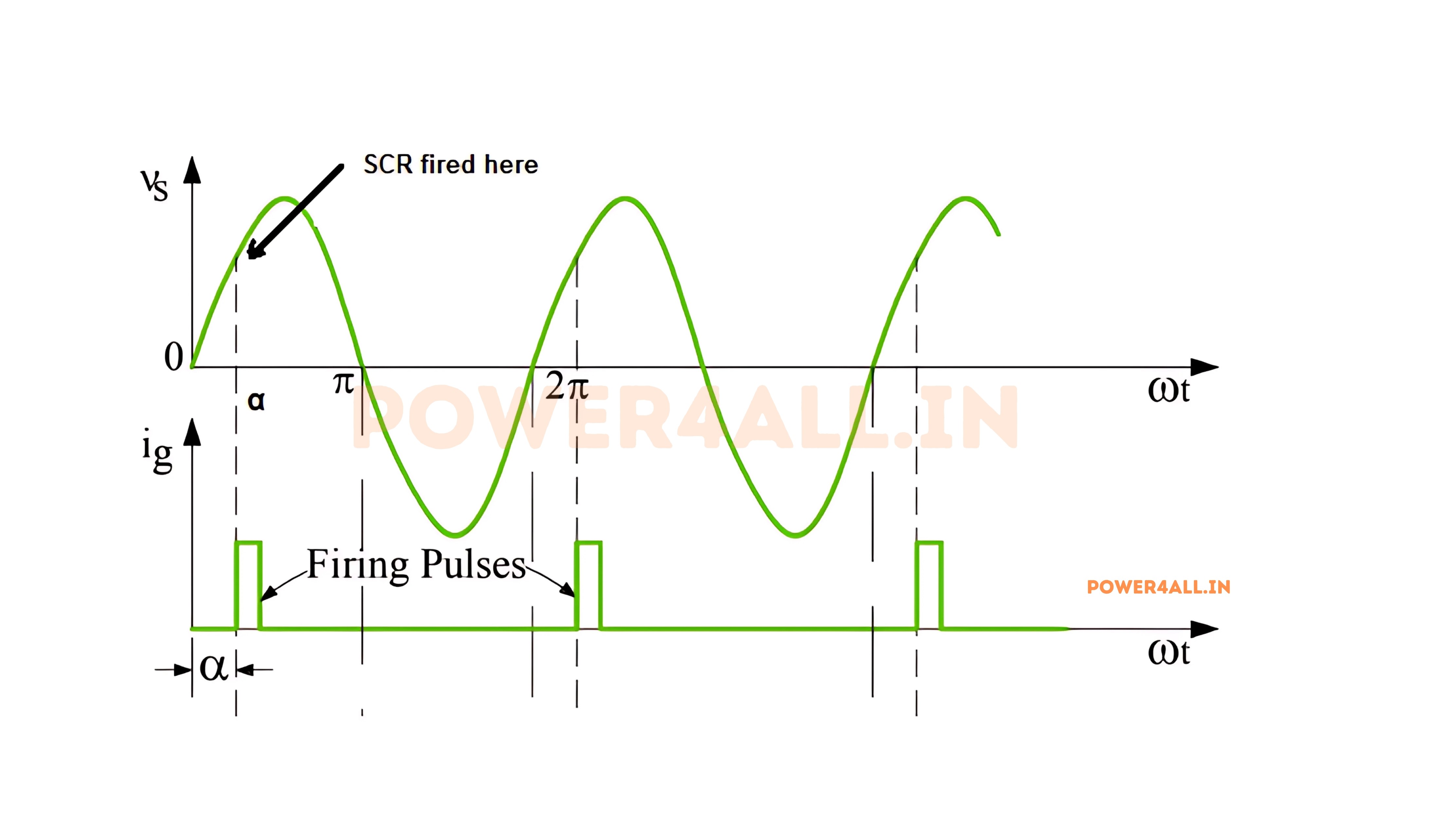
Phase Control Fundamentals
Operating Principle
Phase control works by delaying the trigger point of the SCR within each AC half-cycle. The later the SCR turns on, the less power is delivered to the load.
Key Concepts
- Firing angle (α): Delay from zero crossing to trigger
- Conduction angle: Time SCR conducts per half-cycle
- RMS voltage: Effective voltage delivered to load
- Power control: Varies from 0% to ~100%
α = ωt
Firing angle in electrical degrees
P = P_max × [1 - α/π + sin(2α)/(2π)]
Power delivered vs firing angle
Power vs Firing Angle
- α = 0°: 100% power (full conduction)
- α = 90°: 50% power
- α = 120°: 25% power
- α = 150°: 6.7% power
- α = 180°: 0% power (no conduction)
Light Dimming Applications
Incandescent Dimming
Most common SCR application in homes and theaters
Circuit Design
- Triac (bidirectional SCR): Controls both half-cycles
- Diac trigger: Provides symmetrical triggering
- RC phase shift: Variable timing circuit
- EMI filter: Reduces electrical noise
Performance Characteristics
- Dimming range: 5% - 100% light output
- Efficiency: High (>90% in SCR, losses in bulb)
- Response: Instant dimming control
- Color temperature: Warmer at low brightness
Theater Dimmer Rack
- Channels: 96-192 individual dimmers
- Power per channel: 2.5kW - 10kW
- Control: DMX512 digital protocol
- Dimming curves: Linear, square law, S-curve
- Protection: Circuit breakers, RFI filters
LED Dimming Considerations
Special considerations for LED lighting
Compatibility Issues
- Minimum load: LEDs may not provide enough current
- Flickering: Some LEDs incompatible with phase control
- Leading edge vs trailing edge: Different dimming methods
- Electronic drivers: Need compatible LED drivers
Solutions
- Dimmable LED drivers: Designed for SCR dimming
- Minimum load resistors: Provide sufficient current
- Leading edge dimmers: Better compatibility
- 0-10V dimming: Alternative control method
LED Dimming Best Practices
Always check LED compatibility with SCR dimmers. Use dimmers specifically rated for LED loads, and consider minimum load requirements to prevent flickering and poor dimming performance.
Motor Speed Control
Variable Speed Control for AC Motors Using Phase Control
Universal Motor Control
Universal motors (series wound) respond well to voltage control, making SCR phase control an effective speed control method.
Speed-Torque Characteristics
Lower voltage reduces speed and available torque. Speed regulation depends on load characteristics and feedback control.
Power Applications
Hand tools, kitchen appliances, vacuum cleaners, and small industrial equipment use SCR motor control.
Protection Features
Current limiting, soft start, and thermal protection prevent motor damage during operation.
Induction Motor Considerations
| Motor Type | Speed Range | Efficiency | Applications | Limitations |
|---|---|---|---|---|
| Universal Motor | 20:1 or higher | Good at rated voltage | Tools, appliances | Brush maintenance |
| Single-Phase Induction | 3:1 typical | Poor at low speed | Fans, pumps | Limited speed range |
| Three-Phase Induction | 2:1 typical | Very poor at low speed | Industrial drives | Not recommended |
Drill Press Speed Control
Variable speed drill press with SCR control:
- Motor: 1HP universal motor
- Speed range: 200 - 3000 RPM
- Control: Potentiometer with SCR phase control
- Features: Soft start, current limiting
- Benefits: Smooth speed control, high torque at low speed
Heating Control Systems
Temperature Control Methods
Precise temperature control using SCR power regulation
Control Strategies
- Continuous phase control: Smooth power variation
- Burst firing: Full cycles on/off (reduces harmonics)
- Zero crossing switching: Minimizes EMI
- Time proportional: Percentage of time on
Feedback Control
- Thermocouple input: High temperature sensing
- RTD sensors: Precision temperature measurement
- PID control: Proportional-Integral-Derivative
- Adaptive control: Self-tuning algorithms
HVAC Applications
Building climate control systems
Electric Heating
- Baseboard heaters: Zone temperature control
- Unit heaters: Industrial space heating
- Radiant panels: Comfort heating systems
- Heat pumps: Auxiliary electric heat
Energy Management
- Load scheduling: Peak demand management
- Setback control: Night/weekend temperature reduction
- Outdoor reset: Temperature compensation
- Duty cycling: Short-term load reduction
Energy = Power × Time × Duty_Cycle
Energy consumption with duty cycling
Phase Control Benefits
Phase control offers smooth power variation, high efficiency, fast response, and simple control circuits. However, it generates harmonics and EMI that may require filtering, especially in sensitive applications.
SCR Selection & Design Guide
Proper SCR selection involves analyzing the application requirements, operating conditions, and safety margins to choose the optimal device. This systematic approach ensures reliable operation and cost-effective solutions.
Application Analysis
Voltage Rating Selection
Determining Required Voltage Ratings and Safety Margins
Peak Voltage Calculations
SCR voltage rating must handle the peak voltage that appears across the device, including transients and line variations.
| System Voltage | Peak Voltage | With 10% Variation | Recommended SCR Rating | Safety Factor |
|---|---|---|---|---|
| 120V RMS | 170V | 187V | 400V | 2.1× |
| 240V RMS | 339V | 373V | 600V | 1.6× |
| 480V RMS | 679V | 747V | 1200V | 1.6× |
| 4160V RMS | 5885V | 6474V | 8500V | 1.3× |
V_peak = √2 × V_RMS × 1.1
Peak voltage with 10% line variation
Transient Considerations
Lightning Surges
Power line transients from lightning can reach 6000V or more. Use surge arresters and proper grounding.
Switching Transients
Motor starting, capacitor switching, and other loads create voltage spikes requiring additional margin.
Temperature Derating
High temperatures reduce voltage rating. Derate voltage rating by 0.1%/°C above 25°C.
Voltage Rating Example
480V motor control application:
- Line voltage: 480V RMS ±10%
- Peak normal: 480 × √2 × 1.1 = 747V
- Switching transients: +50% = 1121V
- Ambient temperature: 50°C (derate 2.5%)
- Required rating: 1121V ÷ 0.975 = 1150V
- Selected SCR: 1600V rating (40% margin)
Current Rating Selection
RMS vs Average Current
Understanding different current specifications
Current Definitions
- IT(RMS): RMS current rating (thermal limit)
- IT(AV): Average current rating (≈ 0.636 × RMS)
- ITSM: Surge current capability (short duration)
- I²t: Energy withstand capability
Application Factors
- Conduction angle: Less than 180° reduces effective rating
- Repetition rate: High frequency switching affects rating
- Ambient temperature: Higher temperature requires derating
- Heat sinking: Proper thermal management essential
I_effective = I_rated × K_temp × K_duty
Effective current rating with derating factors
Thermal Design
Heat sink sizing and thermal management
Power Dissipation
- Conduction losses: VT × IT(AV) (main component)
- Switching losses: Usually negligible for SCRs
- Gate losses: VGT × IGT (very small)
- Leakage losses: VDRM × IDRM (negligible)
Heat Sink Calculation
Heat Sink Example
50A SCR, 30A average current:
- Forward drop: VT = 1.7V
- Power dissipation: 1.7V × 30A = 51W
- RθJC: 0.5°C/W
- RθCS: 0.2°C/W (with thermal compound)
- Required RθSA: (125°C - 40°C)/51W - 0.7°C/W = 1.0°C/W
Protection Circuit Design
Overcurrent Protection
Protecting SCRs from excessive current
Protection Methods
- Fast-acting fuses: Semiconductor-type fuses
- Current limiting reactors: Limit di/dt and fault current
- Current transformers: Monitor and trip circuits
- Electronic protection: Fast overcurrent detection
Fuse Selection
- I²t coordination: Fuse I²t < SCR I²t
- Peak let-through: Limit peak fault current
- Voltage rating: Equal to or greater than system voltage
- Time-current curves: Coordinate with load characteristics
Snubber Circuits
Protecting against voltage transients and dv/dt
RC Snubber Design
- Capacitor value: C = IT² × ton / (2V² × (dv/dt))
- Resistor value: R = 0.5 × √(L/C)
- Power rating: PR = 0.5 × C × V² × f
- Component selection: Use quality, high-frequency components
Design Guidelines
- Individual snubbers: One per SCR for best protection
- Component placement: Close to SCR terminals
- Wire inductance: Minimize lead length
- Power dissipation: Adequate power rating for resistor
Snubber Design Example
25A, 600V SCR in motor starter:
- Circuit inductance: L = 50µH
- dv/dt rating: 500V/µs
- Capacitor: C = 25² × 2µs / (2 × 600² × 500) = 0.35µF
- Resistor: R = 0.5 × √(50µH/0.35µF) = 6Ω
- Power: PR = 0.5 × 0.35µF × 600² × 60Hz = 2.3W → use 5W
Gate Drive Circuit Design
Reliable Gate Triggering Circuit Design
Gate Drive Requirements
Proper gate drive ensures reliable SCR triggering under all operating conditions while protecting the gate from damage.
| Parameter | Design Goal | Typical Value | Considerations |
|---|---|---|---|
| Gate Current | 3-5× IGT minimum | 10-500mA | Temperature variation, aging |
| Pulse Duration | Until IL reached | 10-100µs | Load characteristics |
| Rise Time | Fast turn-on | <1µs | di/dt capability |
| Peak Current | Within IGM rating | <2A typical | Gate damage limit |
Isolation Methods
Pulse Transformers
Provide excellent isolation and can drive multiple SCRs. Require careful design for proper pulse shape and timing.
Optocouplers
Simple, cost-effective isolation with good noise immunity. Available in various current ratings and speeds.
Gate Drive ICs
Integrated solutions with built-in protection, level shifting, and optimized drive characteristics.
Optocoupler Gate Drive
Isolated gate drive using MOC3041:
- Input current: 15mA LED current
- Output current: 100mA peak gate current
- Isolation voltage: 7500V RMS
- Zero crossing detection: Built-in for low EMI
- Applications: Solid state relays, motor controls
SCR Testing & Troubleshooting
Proper testing and troubleshooting techniques are essential for maintaining SCR circuits and identifying failures. Understanding common failure modes and diagnostic methods enables quick problem resolution and prevents costly downtime.
Basic SCR Testing
Multimeter Testing
Simple go/no-go tests using a standard multimeter
Diode Test Mode
- Gate-Cathode junction: Should read like a diode (0.7V)
- Anode-Cathode (OFF): Open circuit (OL)
- Reverse bias: All junctions should be open
- Triggering test: Apply voltage to gate while testing A-K
Test Procedure
Test Results Interpretation
- Good SCR: Gate-cathode = 0.6-0.8V, A-K = OL when off
- Shorted SCR: A-K reads low resistance continuously
- Open gate: Gate-cathode reads OL
- Leaky: High but finite resistance A-K when off
Simple Triggering Test
Verify SCR can be triggered and latched
Test Circuit Components
- DC supply: 12V with current limiting resistor
- Load resistor: 1kΩ to provide holding current
- Gate resistor: 1kΩ to limit gate current
- Momentary switch: Apply gate trigger
Test Procedure
- Connect circuit: SCR in series with load and supply
- Initial state: No current should flow
- Apply trigger: Momentary gate current
- Verify latching: Current continues after gate removed
- Turn off: Interrupt anode current to turn off SCR
Safety Precaution
Always use current-limiting resistors in test circuits to prevent damage to the SCR and test equipment. Never exceed the SCR's maximum ratings during testing.
Advanced Testing Methods
Curve Tracer and Parametric Testing
Curve Tracer Testing
Curve tracers provide detailed I-V characteristics and can measure critical parameters under controlled conditions.
Blocking Characteristics
Measure leakage current vs voltage to verify blocking capability and identify degradation.
Triggering Sensitivity
Determine actual IGT and VGT values to verify specifications and design margins.
On-State Voltage
Measure VT at rated current to calculate power dissipation and thermal requirements.
Parametric Test Equipment
| Parameter | Test Equipment | Test Conditions | Acceptance Criteria |
|---|---|---|---|
| VDRM | High voltage tester | Rated voltage, 25°C | IDRM < spec limit |
| IGT, VGT | Curve tracer | Specified test current | Within datasheet limits |
| VT | DC source/meter | Rated current | < Maximum spec |
| IH | Current source | 25°C ambient | Maintains conduction |
Production Test Sequence
Automated test sequence for SCR qualification:
- Visual inspection: Package damage, marking verification
- Electrical tests: VDRM, IGT, VGT, VT, IH measurements
- Thermal tests: Junction temperature vs power
- Dynamic tests: Switching times, dv/dt, di/dt
- Reliability screening: Temperature cycling, burn-in
Common Failure Modes
Short Circuit Failures
Most common SCR failure mode
Causes
- Overcurrent: Exceeding IT rating or I²t capability
- Overvoltage: Breakdown due to excessive forward or reverse voltage
- dv/dt triggering: False turn-on causing shoot-through
- Thermal overstress: Junction temperature exceeding limits
Symptoms
- Continuous conduction: SCR always on regardless of gate
- Low resistance: A-K resistance very low in both directions
- Fuse blowing: Protective fuses operate repeatedly
- Overheating: Excessive heat generation in SCR
Troubleshooting Short Circuit
- Disconnect and test: Remove SCR from circuit
- Resistance check: Measure A-K resistance
- Visual inspection: Look for package damage
- Root cause analysis: Identify why failure occurred
Open Circuit Failures
Less common but can occur in high-stress applications
Causes
- Bond wire failure: Internal connections break
- Die cracking: Thermal or mechanical stress
- Metallization failure: Contact degradation
- Package damage: Lead frame or die attach failure
Symptoms
- No conduction: SCR never turns on
- High resistance: Open circuit A-K and/or gate
- Intermittent operation: Works sometimes, fails others
- No gate control: Gate has no effect on conduction
Gate Degradation
- Increased IGT: Requires more current to trigger
- Poor sensitivity: Unreliable triggering
- Gate leakage: Increased gate-cathode current
- Temperature sensitivity: Works at room temp, fails when hot
In-Circuit Troubleshooting
Circuit-Level Diagnostics
Troubleshooting without removing components
Voltage Measurements
- Anode voltage: Should equal supply when off
- Cathode voltage: Near ground when off
- Gate voltage: Check trigger signal presence
- VCE when on: Should be 1-2V when conducting
Current Measurements
- Load current: Verify proper conduction
- Gate current: Confirm adequate trigger signal
- Leakage current: Check for degradation
- Supply current: Overall circuit operation
Motor Control Troubleshooting
Single-phase motor not starting:
- Check supply voltage: Verify proper AC input
- Gate signal: Confirm trigger pulses present
- SCR conduction: Measure voltage drop when on
- Load continuity: Verify motor winding integrity
- Snubber circuits: Check for component failures
Waveform Analysis
Using oscilloscopes for dynamic troubleshooting
Key Waveforms
- Anode voltage: Should show proper phase control
- Gate trigger: Timing and amplitude verification
- Load current: Proper conduction angle
- dv/dt stress: Check for excessive voltage rates
Common Waveform Issues
- Missing triggers: Gate drive circuit failure
- Jitter: Noise or unstable triggering
- False triggering: dv/dt or noise problems
- Poor commutation: Turn-off problems
Oscilloscope Safety
When measuring high-voltage SCR circuits, use differential probes or isolated channels to prevent ground loops and ensure operator safety. Never exceed the oscilloscope's maximum input voltage rating.
Testing Best Practices
Always follow proper safety procedures when testing SCRs. Use appropriate test equipment, verify circuit de-energization, and understand the expected behavior before applying power. Systematic testing approaches prevent equipment damage and ensure accurate diagnosis.
Safety Considerations for SCR Applications
Working with SCRs, especially in high-power applications, requires careful attention to safety. SCRs often control dangerous voltages and currents, making proper safety practices essential for protecting both personnel and equipment during design, installation, and maintenance.
Electrical Safety
High Voltage Precautions
Protecting against electrical shock and arc flash
Voltage Safety Measures
- Lockout/Tagout: Ensure power cannot be accidentally restored
- Voltage verification: Test with proper meters before working
- Proper PPE: Insulated gloves, safety glasses, arc-rated clothing
- Safe working distance: Maintain appropriate clearances
- Ground fault protection: GFCI protection where required
Arc Flash Protection
- Arc flash analysis: Calculate incident energy levels
- Protective equipment: Arc-rated PPE based on energy levels
- Safe practices: Avoid energized work when possible
- Warning labels: Proper arc flash hazard labeling
High Voltage Warning
SCR circuits often operate at dangerous voltages. Always assume circuits are energized until proven otherwise with proper test equipment. High-voltage SCR circuits can be lethal - follow all electrical safety codes and company procedures.
Grounding and Isolation
Proper grounding protects personnel and equipment
Grounding Requirements
- Equipment grounding: All metal enclosures must be grounded
- System grounding: Proper neutral and ground connections
- Isolation transformers: Provide electrical isolation
- Ground fault detection: Monitor insulation integrity
- Lightning protection: Surge arresters for outdoor equipment
Isolation Techniques
- Optical isolation: Optocouplers for gate drives
- Magnetic isolation: Pulse transformers
- Barrier strips: Physical separation of circuits
- Enclosure design: Prevent accidental contact
Grounding Best Practices
- Single point grounding: Avoid ground loops
- Low impedance paths: Use adequate conductor sizes
- Corrosion protection: Proper ground connections
- Regular testing: Verify ground integrity periodically
Thermal Safety
Heat Management Safety
SCRs generate significant heat during operation. Proper thermal management prevents fires, equipment damage, and thermal injuries to personnel.
Fire Prevention
- Adequate heat sinking: Prevent overheating
- Ventilation clearances: Allow proper airflow
- Temperature monitoring: Thermal sensors and alarms
- Fire suppression: Appropriate extinguishing systems
- Hot surface protection: Guards and warning labels
Burn Hazard Warning
Heat sinks and power semiconductors can reach temperatures over 100°C during normal operation. Use caution when working near hot surfaces and allow adequate cooling time before handling components.
Thermal Safety Checklist
- Temperature limits: Monitor junction temperatures
- Cooling systems: Verify fan operation and airflow
- Thermal protection: Overtemperature shutdowns
- Maintenance access: Safe component replacement procedures
Operational Safety
Safe Operating Procedures
Procedures to prevent accidents and equipment damage
Pre-Operation Checks
- Visual inspection: Check for damage or loose connections
- Cooling system: Verify fans, pumps, and airflow
- Protection circuits: Test fuses, breakers, and trips
- Control circuits: Verify proper gate drive operation
- Emergency stops: Test all shutdown systems
Operating Limits
- Voltage ratings: Never exceed VDRM specifications
- Current ratings: Stay within IT specifications
- Temperature limits: Monitor junction temperatures
- Duty cycle: Respect thermal cycling limits
- Switching frequency: Consider switching losses
Emergency Procedures
Response procedures for fault conditions
Emergency Shutdown
- Emergency stop buttons: Easily accessible shutdown
- Automatic protection: Overcurrent and overvoltage trips
- Fire suppression: Automatic fire detection and suppression
- Ventilation systems: Emergency exhaust for smoke/fumes
- Communication: Alert systems for personnel
Fault Response
- Do not reset: Investigate cause before restart
- Isolate power: Secure energy sources
- Document faults: Record for troubleshooting
- Professional help: When in doubt, call experts
Emergency Response
In case of SCR failure with smoke, fire, or electrical arcing: 1) Immediately shut off power if safely possible, 2) Evacuate the area, 3) Call emergency services if needed, 4) Do not attempt repairs until system is safe and de-energized.
Installation and Maintenance Safety
Safe Installation, Commissioning, and Maintenance Practices
Installation Safety
Proper Tools and Equipment
Use insulated tools, proper lifting equipment for heavy components, and calibrated test equipment for commissioning.
Qualified Personnel
Only trained and qualified electricians should install high-power SCR systems. Proper training reduces accident risk.
Code Compliance
Follow all applicable electrical codes, standards, and manufacturer instructions for safe installation.
Environmental Protection
Ensure proper IP ratings for environmental conditions and adequate protection from moisture and contaminants.
Maintenance Safety
| Maintenance Task | Safety Precautions | Required PPE | Special Considerations |
|---|---|---|---|
| Visual Inspection | Power off, LOTO | Safety glasses, gloves | Check for overheating signs |
| Thermal Imaging | Energized equipment | Arc flash PPE | Maintain safe distance |
| Connection Tightening | Power off, LOTO | Insulated tools | Proper torque specifications |
| SCR Replacement | Power off, discharge caps | Full electrical PPE | ESD protection required |
| Testing/Commissioning | Follow test procedures | Arc flash rated PPE | Qualified personnel only |
Maintenance Safety Checklist
- Work permits: Obtain proper authorization
- Isolation procedures: Verify zero energy state
- Communication: Coordinate with operations personnel
- Documentation: Record all work performed
- Testing: Verify proper operation before returning to service
Frequently Asked Questions about SCRs
Common questions and answers about SCR operation, selection, troubleshooting, and applications. These FAQs address the most frequent concerns from engineers, technicians, and students working with silicon controlled rectifiers.
Basic Operation Questions
What is the difference between an SCR and a regular diode?
While both are semiconductor devices, they have fundamental differences:
| Characteristic | Diode | SCR |
|---|---|---|
| Terminals | 2 (Anode, Cathode) | 3 (Anode, Cathode, Gate) |
| Layers | 2 (P-N) | 4 (P-N-P-N) |
| Conduction | Automatic when forward biased | Requires gate trigger |
| Control | Voltage controlled | Current controlled (gate) |
| Turn-off | Automatic with reverse bias | Current must go to zero |
Key advantage: SCRs can handle much higher currents and provide controllable switching, making them ideal for power control applications.
Why doesn't my SCR turn off when I remove the gate signal?
This is normal SCR behavior called "latching." Once triggered on, the SCR remains conducting until the anode current drops below the holding current (IH), regardless of the gate signal.
How to turn off an SCR:
- AC circuits: Current naturally goes to zero each half-cycle
- DC circuits: Must interrupt the anode current externally
- Commutation circuits: Use capacitors or additional switches
- Series switch: Another switch in series with the load
Remember
The gate only controls turn-ON, not turn-OFF. This is the fundamental difference between SCRs and transistors.
How do I choose the right SCR voltage and current ratings?
Voltage Rating Selection:
- Calculate peak voltage: √2 × RMS voltage × 1.1 (for 10% variation)
- Add safety margin: Use 60-80% of SCR rating
- Consider transients: Lightning, switching spikes
- Temperature derating: Higher temperatures reduce ratings
Current Rating Selection:
- RMS current: Continuous operating current
- Average current: For DC and rectifier applications
- Surge current: Short-term overload capability
- Thermal design: Adequate heat sinking required
Selection Example
240V AC motor control, 20A RMS:
- Peak voltage: 240 × 1.414 × 1.1 = 373V
- With safety margin: 373V ÷ 0.8 = 466V → use 600V SCR
- Current rating: 20A ÷ 0.8 = 25A → use 35A SCR
Application and Design Questions
Can I use an SCR to control DC loads?
Yes, but with important limitations:
DC Control Challenges:
- Turn-off problem: DC current doesn't naturally go to zero
- Commutation required: External circuits needed to turn off
- Complex control: More complicated than AC control
- Cost considerations: May be more expensive than alternatives
Better Alternatives for DC:
- MOSFETs: Easy gate control, efficient switching
- IGBTs: High power, easy control
- BJTs: Simple for low power applications
- Contactors/Relays: Simple on/off control
Recommendation
Use SCRs primarily for AC applications. For DC control, consider MOSFETs or IGBTs which offer easier control and better performance.
How much gate current does my SCR need?
Gate current requirements depend on SCR size and application requirements:
| SCR Current Rating | Typical IGT | Recommended Gate Drive | Applications |
|---|---|---|---|
| 1-10A | 1-10mA | 10-50mA | Small power control |
| 25-50A | 10-50mA | 50-200mA | Motor starters, heating |
| 100-500A | 50-200mA | 200mA-1A | Industrial drives |
| 1000A+ | 200mA-1A | 1-5A | High power systems |
Design Guidelines:
- Safety factor: Use 3-5× the minimum IGT
- Temperature effects: IGT increases at low temperature
- Noise immunity: Higher drive current improves noise rejection
- Fast switching: Higher current for faster turn-on
Troubleshooting Questions
My SCR fails immediately after installation. What could be wrong?
Common Causes of Immediate Failure:
Overvoltage
- Voltage rating too low for application
- Transient voltages from switching
- Lightning or power line surges
- Missing or inadequate snubber circuits
Overcurrent
- Short circuit in load or wiring
- Inadequate current limiting
- Wrong fuse or breaker sizing
- Excessive inrush current
Thermal Issues
- Inadequate heat sinking
- Poor thermal interface
- Blocked airflow or cooling
- Ambient temperature too high
Diagnostic Steps:
My SCR turns on by itself without a gate signal. Why?
Unwanted triggering can occur due to several factors:
Common Causes:
- dv/dt triggering: Rapid voltage changes across the SCR
- Noise pickup: Electrical noise on gate circuit
- Temperature effects: High temperature increases leakage
- Light triggering: Some SCRs are light-sensitive
- Breakover voltage: Applied voltage exceeds VBO
Solutions:
- RC snubber: Limit dv/dt across SCR
- Gate resistor: 1kΩ from gate to cathode
- Shielded cables: Reduce noise pickup
- Proper grounding: Minimize ground loops
- Temperature control: Adequate cooling
- Light shielding: Protect from bright lights
Anti-False Trigger Circuit
- RC snubber: 0.1µF + 100Ω across SCR
- Gate resistor: 1kΩ gate-to-cathode
- Gate drive isolation: Optocoupler or transformer
- Filtering: Ferrite beads on gate leads
Mastering SCR Technology: Your Path Forward
Silicon Controlled Rectifiers remain fundamental components in modern power electronics, from simple light dimmers to massive industrial drives and HVDC transmission systems. Understanding SCR principles, characteristics, and applications opens doors to designing efficient, reliable power control solutions.
Key Takeaways
Fundamental Understanding
SCRs are four-layer PNPN devices that provide controllable, high-power switching with simple gate triggering and natural commutation in AC circuits.
Practical Applications
From 1A light dimmers to 5000A industrial drives, SCRs excel in phase control, motor drives, heating systems, and power conversion applications.
Design Considerations
Proper voltage/current rating, thermal management, gate drive design, and protection circuits are essential for reliable SCR operation.
Troubleshooting Skills
Understanding failure modes, testing procedures, and safety practices enables effective maintenance and problem resolution in SCR systems.
Knowledge + Practice = Expertise
Your journey to SCR mastery starts with understanding fundamentals and grows through practical application
Thank you for exploring the world of Silicon Controlled Rectifiers!
Continue your electronics journey with our other comprehensive guides and resources.