Complete Voltage Mastery Guide
Master the fundamentals of electrical voltage - from basic electric potential difference to advanced circuit analysis, measurement techniques, and safety considerations in modern electrical systems.
Complete Learning Path - Voltage Fundamentals to Applications
Navigate through comprehensive coverage of voltage from basic principles to advanced applications
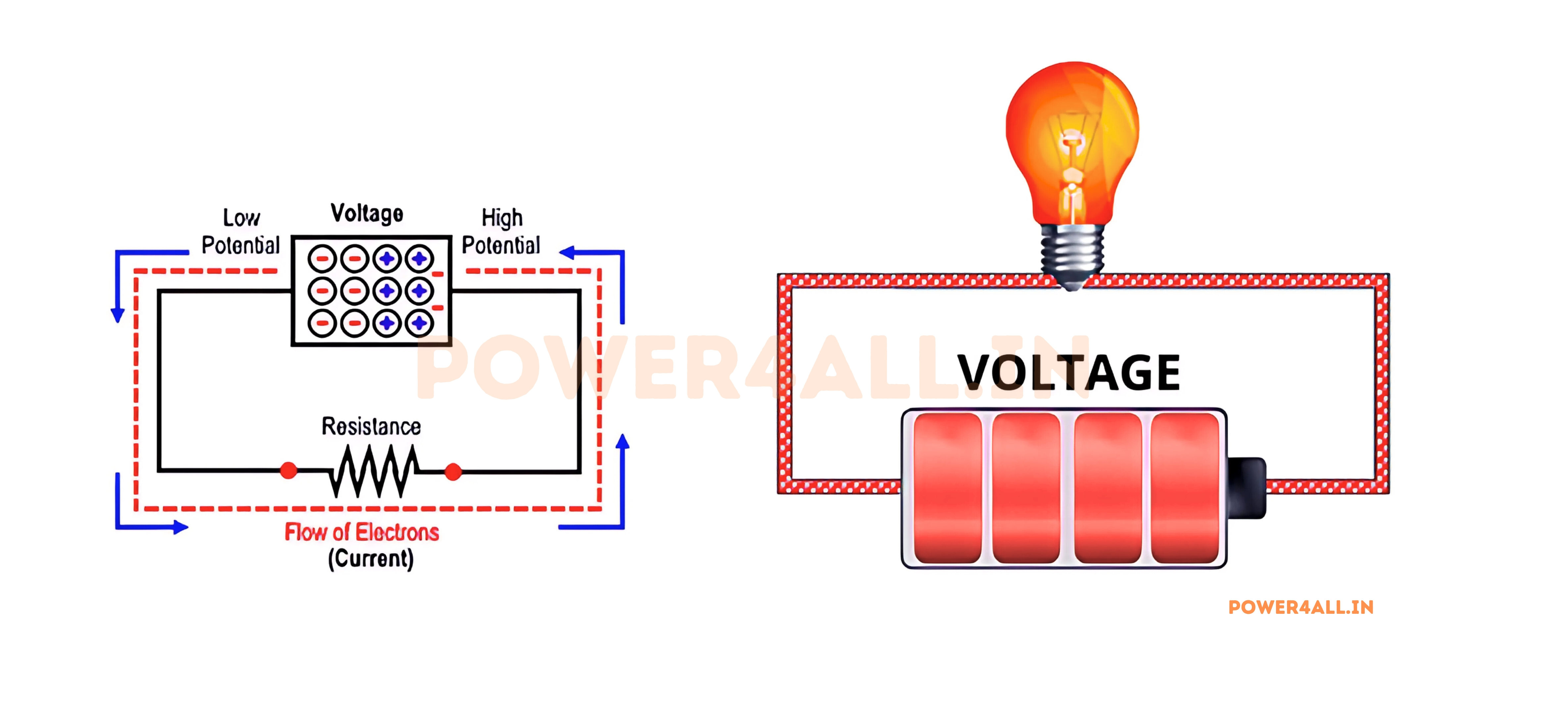
What is Voltage?
Voltage, also known as electric potential difference, is the driving force that pushes electric charge through a circuit. Think of it as the "electrical pressure" that makes electrons move from one point to another, similar to how water pressure pushes water through pipes.
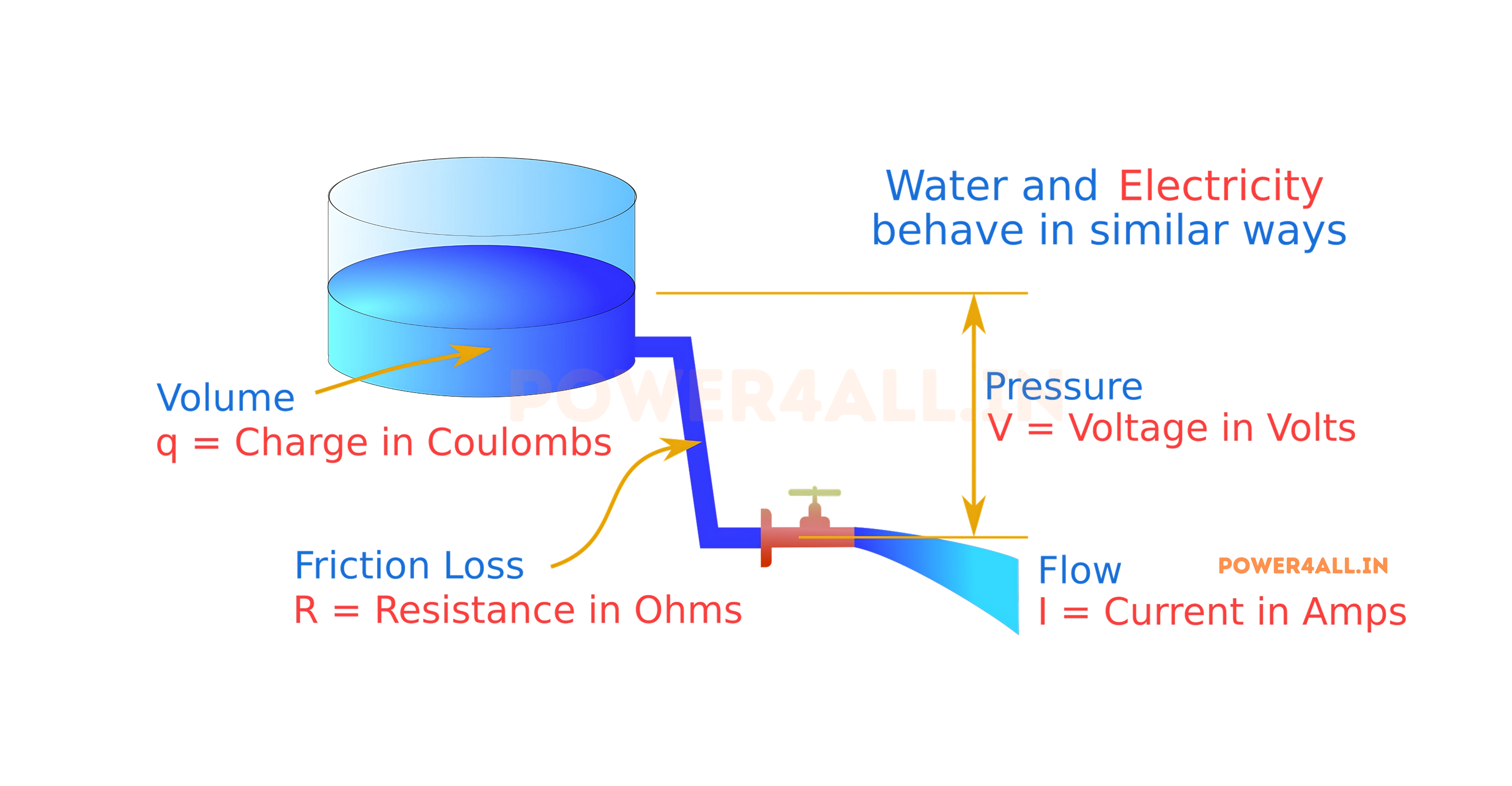
The Water Tank Analogy
Imagine a water tank on a hill connected to a pipe leading to your house below. The height difference creates water pressure that pushes water through the pipe. Similarly, voltage is the "electrical height difference" that pushes electrons through wires.
Real-World Comparison
- Water pressure ↔ Voltage (electrical pressure)
- Water flow rate ↔ Current (electron flow)
- Pipe resistance ↔ Electrical resistance
- Height difference ↔ Potential difference
- Water pump ↔ Battery or power supply
- Narrow pipe ↔ High resistance component
V = W / Q
Voltage (V) equals Work done (W) divided by Charge (Q)
Scientific Definition and Units
Voltage is defined as the amount of work (energy) needed to move one unit of electric charge from one point to another. It's measured in volts (V), named after Alessandro Volta, the inventor of the electric battery in 1800.
Key Understanding
Voltage doesn't exist at a single point - it only exists between two points. It's always a difference in electric potential, which is why we often call it "potential difference" or "voltage drop" across a component.
Why Voltage is Essential in Electrical Systems
Drives Electric Current
Without voltage, there would be no current flow. Voltage provides the electromotive force (EMF) needed to move electrons through conductors, making all electrical devices possible.
Energy Transfer Mechanism
Voltage represents the energy available per unit charge. Higher voltage means more energy can be transferred to do useful work like lighting bulbs, running motors, or charging batteries.
Controls Circuit Behavior
The voltage levels in a circuit determine how components operate. Different devices require specific voltages to function correctly - too little and they won't work, too much and they may be damaged.
Universal Energy Carrier
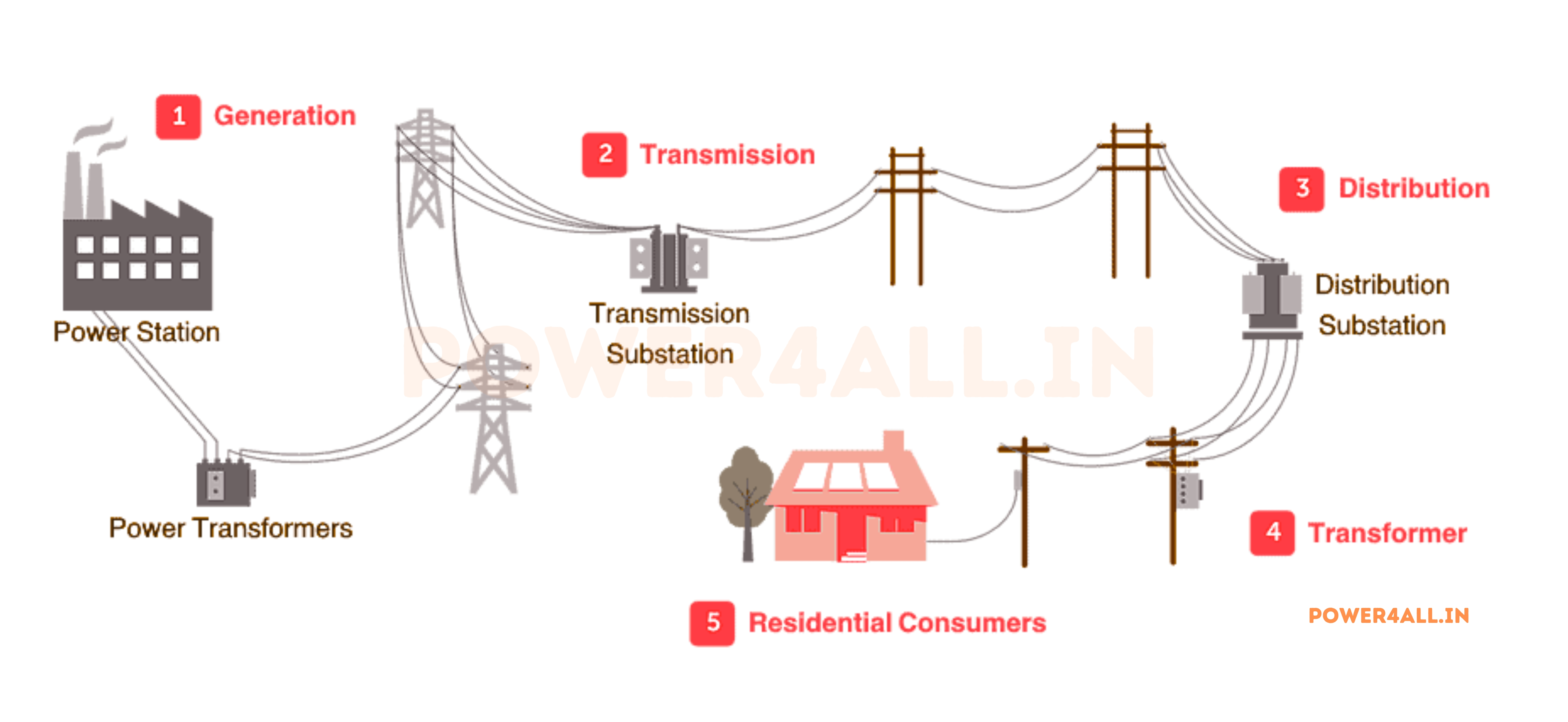
Voltage allows us to transport electrical energy efficiently over long distances through power lines, enabling the modern electrical grid that powers cities and industries worldwide.
Historical Background and Development
The Discovery and Understanding of Voltage
The concept of electric potential was first developed by Alessandro Volta in the 1790s while studying the work of Luigi Galvani on "animal electricity." Volta's systematic experiments led to groundbreaking discoveries.
Volta's Revolutionary Voltaic Pile
Volta's battery consisted of alternating discs of zinc and copper separated by cardboard soaked in salt water. This simple design could produce about 1 volt per cell, and multiple cells could be stacked to increase voltage - the first practical source of continuous electric current.
Common Misconceptions About Voltage
| Common Myth | Reality | Why It Matters | Practical Example |
|---|---|---|---|
| "High voltage is always dangerous" | Danger depends on both voltage AND current | Understanding safety requires both factors | Static electricity: 10,000V but tiny current = harmless |
| "Voltage flows through circuits" | Current flows, voltage is the driving pressure | Fundamental to understanding circuits | Water flows through pipes, pressure drives the flow |
| "Batteries store voltage" | Batteries store chemical energy, produce voltage | Explains battery behavior and limitations | Dead battery has no voltage because chemicals are depleted |
| "AC and DC voltage are the same" | They behave very differently in circuits | Critical for proper equipment selection | DC motor won't work on AC, and vice versa |
Voltage Fundamentals: Deep Understanding
Understanding voltage fundamentals involves exploring the relationship between electric charge, energy, and the force that creates potential difference. These concepts form the foundation of all electrical phenomena and circuit analysis.
Electric Potential and Potential Difference
Electric Potential: The Foundation Concept
Electric potential is the amount of electric potential energy per unit charge at a specific point in space. It's measured in volts and represents the work needed to bring a unit positive charge from infinity (zero potential reference) to that point.
V = U / q
Electric Potential (V) = Potential Energy (U) / Charge (q)
Understanding Potential Energy in Electric Fields
Practical Example: 9V Battery Analysis
A 9V battery creates a potential difference of 9 volts between its terminals:
- Energy per charge: Each coulomb gains 9 joules moving from negative to positive terminal
- Work capability: Can do 9 joules of work per coulomb in external circuit
- Power relationship: Provides 9 watts of power for every ampere of current
- Practical meaning: Can light a 9W LED for 1 hour with 1 ampere-hour capacity
Voltage Measurement Units and Standards
| Unit Name | Symbol | Value in Volts | Common Applications | Typical Range | Examples |
|---|---|---|---|---|---|
| Volt | V | 1 | Household electronics, batteries | 1V - 1000V | Car battery: 12V, Wall outlet: 120V/230V |
| Millivolt | mV | 10⁻³ | Sensor signals, microelectronics | 1mV - 1000mV | Thermocouple: 40mV, Microphone: 2mV |
| Microvolt | μV | 10⁻⁶ | EEG, ECG, precision measurements | 1μV - 1000μV | Brain waves: 50μV, Heart signals: 1mV |
| Kilovolt | kV | 10³ | Power transmission, X-ray machines | 1kV - 1000kV | Distribution line: 13.8kV, X-ray: 100kV |
| Megavolt | MV | 10⁶ | Lightning, particle accelerators | 1MV - 100MV | Lightning bolt: 100MV, Van de Graaff: 1MV |
International Voltage Standard
The volt is defined in terms of other SI units: 1 volt = 1 joule per coulomb = 1 watt per ampere. Since 2019, it's defined using fundamental physical constants including Planck's constant and elementary charge, providing the most accurate and stable voltage reference possible.
Relationship Between Voltage, Current, and Resistance
Voltage doesn't exist in isolation - it's intimately connected with current and resistance through fundamental electrical laws that govern all circuit behavior.
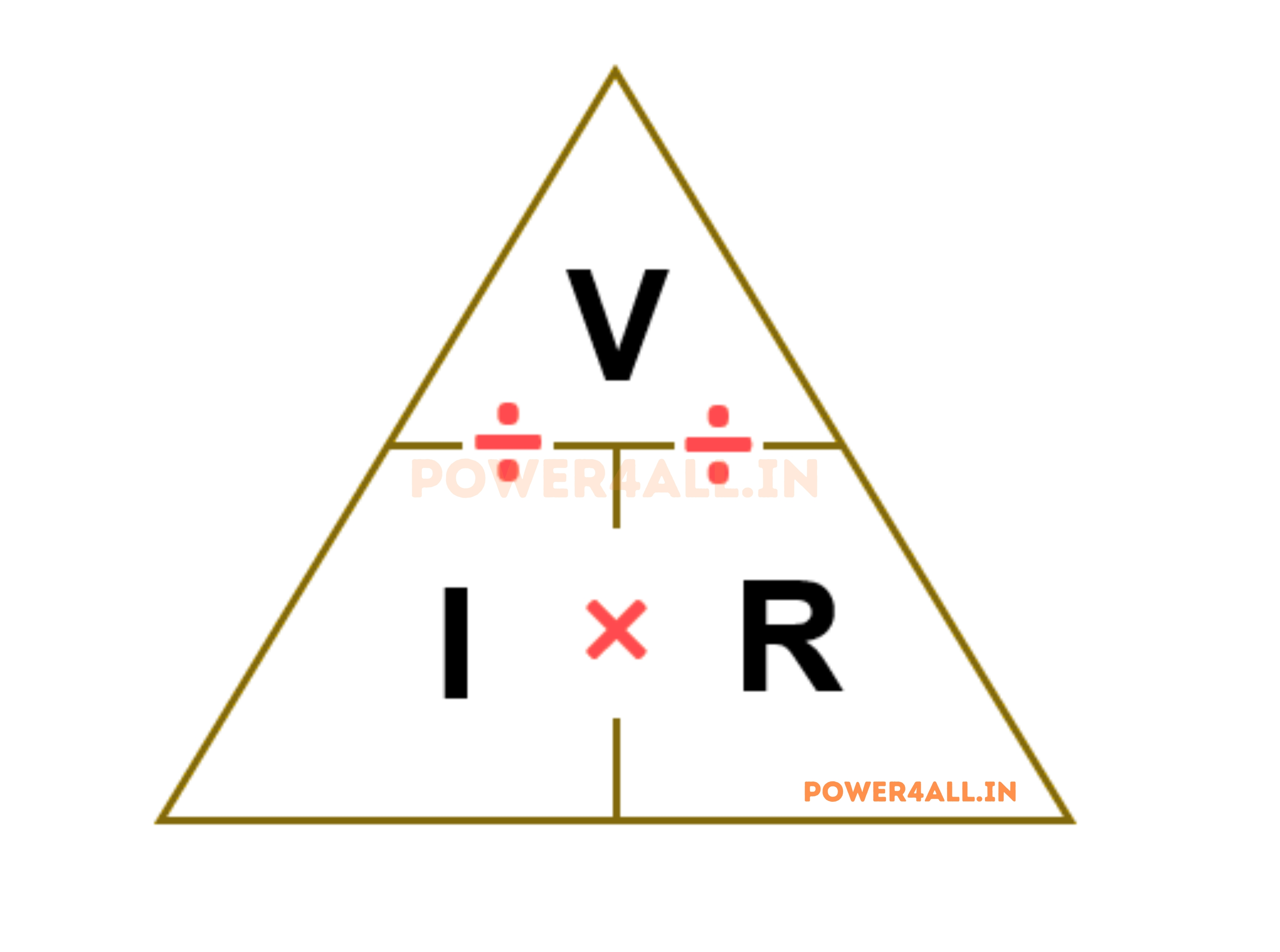
V = I × R
Ohm's Law: Voltage = Current × Resistance
Voltage (V)
Definition: Electric potential difference
Water Analogy: Water pressure in pipes
Unit: Volts (V)
Symbol: V or U in circuit diagrams
Measurement: Across components (in parallel)
Nature: Driving force for current flow
Current (I)
Definition: Flow of electric charge
Water Analogy: Water flow rate (gallons/minute)
Unit: Amperes (A)
Symbol: I in circuit diagrams
Measurement: Through components (in series)
Nature: Result of voltage applied across resistance
Resistance (R)
Definition: Opposition to current flow
Water Analogy: Pipe friction and narrowness
Unit: Ohms (Ω)
Symbol: R in circuit diagrams
Measurement: With power disconnected
Nature: Material property limiting current
Energy and Power Relationships
Power and Energy in Electrical Circuits
P = V × I = V² / R = I² × R
Power relationships combining voltage, current, and resistance
Complete Power Calculation Example
Given: 12V power supply connected to 4Ω resistor
Energy Conversion and Conservation
Resistive Loads
In resistors, electrical energy converts entirely to heat. This is useful in heaters and incandescent bulbs but represents loss in most other applications.
Light Generation
LEDs and fluorescent lights convert electrical energy to light with much higher efficiency than incandescent bulbs, reducing waste heat.
Mechanical Work
Motors convert electrical energy to mechanical energy with 80-95% efficiency, with losses appearing as heat in windings and mechanical friction.
Energy Storage
Batteries and capacitors store electrical energy chemically or in electric fields, with some energy lost as heat during charging and discharging.
How Voltage Works: The Complete Process
Understanding how voltage actually works requires examining the atomic-level behavior of electrons, the creation of electric fields, and the mechanisms that establish and maintain potential differences in electrical systems.
The Atomic and Molecular Perspective
From Atoms to Voltage: The Complete Picture
Electron Behavior in Different Materials
Fascinating Facts About Electron Motion
- Drift speed: Electrons move at only ~1mm/second in typical wires
- Random motion: Individual electrons move at 1,000 km/second randomly
- Net movement: Voltage causes small net drift in one direction
- Quantity: About 6.24×10¹⁸ electrons per ampere per second
- Signal speed: Electric field propagates at ~70% speed of light
- Direction: Electrons flow opposite to conventional current
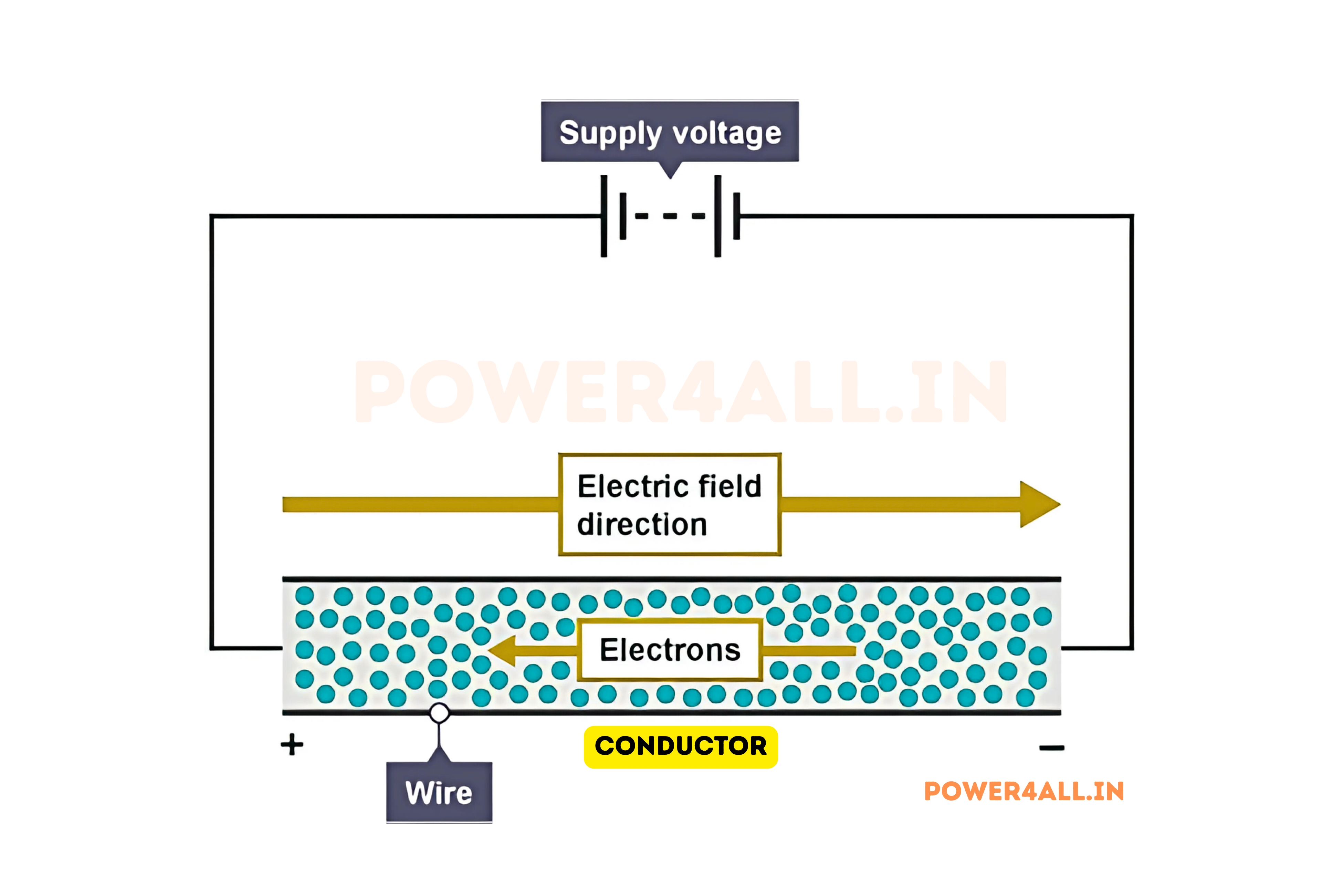
Electric Field Creation and Propagation
How Voltage Creates and Maintains Electric Fields
Voltage doesn't directly push electrons - it creates an electric field throughout the conductor that exerts force on all free charges simultaneously. This field is what actually drives current flow.
Electric Field Strength and Direction
E = V / d
Electric Field Strength (E) = Voltage (V) / Distance (d)
Field Properties
- Direction: Always from positive to negative potential
- Strength: Inversely proportional to distance between potentials
- Uniformity: Constant in uniform conductors and parallel plates
- Propagation speed: Established at nearly speed of light
- Penetration: Extends throughout conducting material
Force on Charge Carriers
- Force equation: F = q × E (force = charge × field)
- Acceleration: F = m × a (Newton's second law)
- Terminal velocity: Balanced by collisions with atoms
- Collective motion: Billions of electrons respond together
- Drift velocity: Net movement much slower than random motion
Why Lights Turn On Instantly
Although individual electrons move slowly through wires, the electric field propagates at nearly light speed. When you flip a switch, the field change reaches all points in the circuit almost instantly, causing immediate current flow and light illumination throughout the entire circuit simultaneously.
Electric Field in Common Applications
- Household wire (12 AWG, 120V): E = 120V/0.1m = 1,200 V/m
- Car battery terminal (12V, 1cm gap): E = 12V/0.01m = 1,200 V/m
- Power line (13.8kV, 3m clearance): E = 13,800V/3m = 4,600 V/m
- Lightning (100MV, 1km): E = 100,000,000V/1000m = 100,000 V/m
- Capacitor plates (1000V, 1mm): E = 1000V/0.001m = 1,000,000 V/m
Voltage Sources and Energy Conversion
Chemical Sources (Batteries)
Process: Chemical reactions create charge separation
- Anode reaction: Releases electrons (oxidation)
- Cathode reaction: Accepts electrons (reduction)
- Electrolyte: Allows ion flow to complete circuit
- Voltage output: Determined by chemical potential difference
Photovoltaic Sources (Solar)
Process: Light energy knocks electrons loose
- Photon absorption: Light provides energy to electrons
- Electron-hole pairs: Creates charge separation
- P-N junction: Built-in field separates charges
- Voltage output: Depends on material bandgap
Electromagnetic Sources (Generators)
Process: Magnetic field changes induce voltage
- Faraday's law: Changing magnetic flux creates voltage
- Mechanical motion: Relative movement between coil and magnet
- AC generation: Sinusoidal voltage output
- Frequency: Determined by rotation speed
Voltage Drop and Distribution
Understanding Voltage Drop in Circuits
As current flows through circuit components, voltage is "used up" or "dropped" across each component, converting electrical energy into other forms.
Kirchhoff's Voltage Law (KVL)
∑V = 0
The sum of all voltage drops in a closed loop equals zero
Series Circuit Example
Circuit: 12V battery, 100Ω and 200Ω resistors in series
Total resistance: R_total = 100Ω + 200Ω = 300Ω
Current: I = V/R = 12V/300Ω = 0.04A
Voltage drops:
- V₁ = I×R₁ = 0.04A×100Ω = 4V
- V₂ = I×R₂ = 0.04A×200Ω = 8V
- Total: 4V + 8V = 12V ✓
Energy Conversion Examples
Resistor (Heat)
Voltage drop across resistors converts electrical energy to heat through electron collisions with atoms.
LED (Light)
Forward voltage drop in LEDs converts electrical energy to photons through electron-hole recombination.
Motor (Motion)
Voltage across motor windings creates magnetic fields that convert electrical energy to mechanical motion.
Types of Voltage: DC vs AC and Beyond
Voltage comes in different forms, each with unique characteristics and applications. Understanding these types is crucial for selecting appropriate power sources and designing circuits for specific needs.
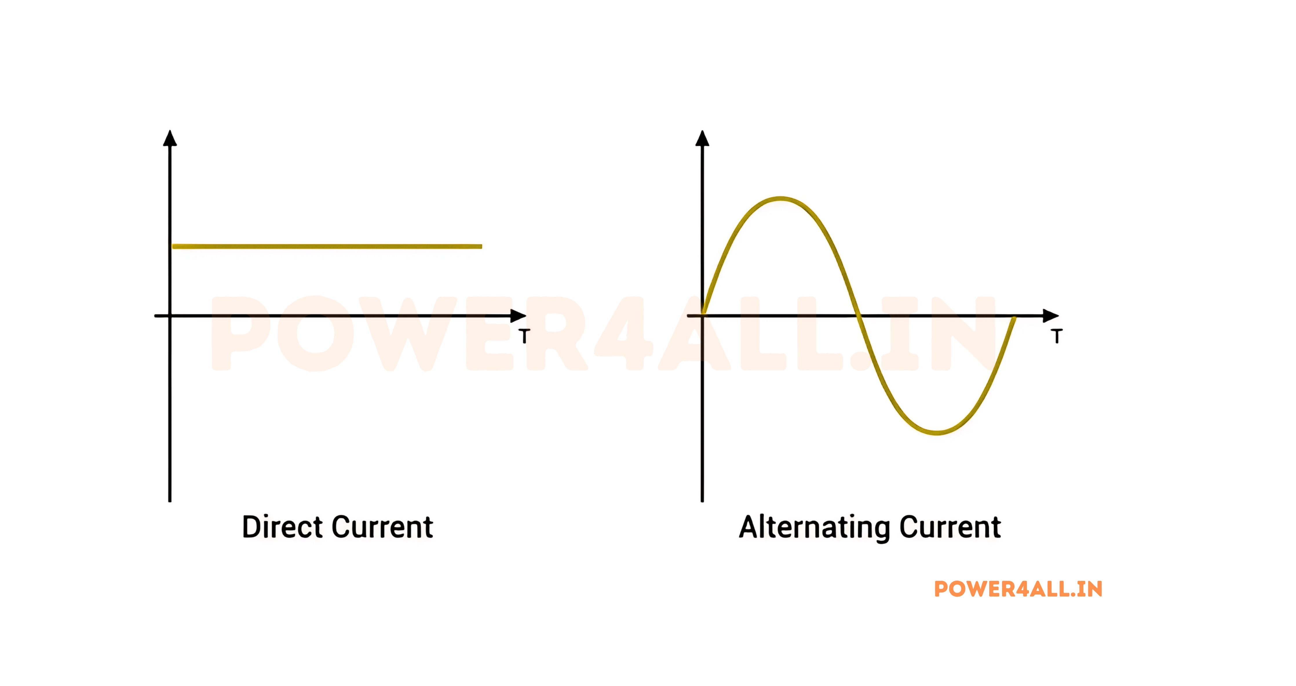
Direct Current (DC) Voltage
Pure DC Voltage
Characteristics: Constant magnitude and polarity
- Voltage level: Remains constant over time
- Polarity: Positive and negative terminals don't change
- Current direction: Always flows in the same direction
- Waveform: Straight horizontal line on oscilloscope
Common Sources
- Batteries (chemical cells)
- DC power supplies
- Solar panels
- DC generators
Pulsating DC Voltage
Characteristics: Varying magnitude but constant polarity
- Ripple voltage: Small AC component on DC base
- Filtering: Capacitors smooth the pulsations
- Regulation: Voltage regulators stabilize output
- Quality factor: Measured by ripple percentage
Common Sources
- Rectified AC (after diode bridge)
- Switching power supplies
- Poorly filtered DC supplies
- Battery chargers
Alternating Current (AC) Voltage
AC Voltage Fundamentals
AC voltage continuously changes magnitude and direction, following a sinusoidal pattern in most power systems.
Key AC Parameters
| Parameter | Definition | Mathematical Expression | Typical Values | Importance |
|---|---|---|---|---|
| Peak Voltage (Vp) | Maximum instantaneous voltage | Vp = √2 × Vrms | 170V (120V RMS) | Insulation design, component ratings |
| RMS Voltage (Vrms) | Effective voltage (heating equivalent) | Vrms = Vp / √2 | 120V, 230V, 480V | Power calculations, standard ratings |
| Peak-to-Peak (Vpp) | Total voltage swing | Vpp = 2 × Vp | 340V (120V RMS) | Oscilloscope measurements |
| Frequency (f) | Cycles per second | f = 1 / T | 50Hz, 60Hz, 400Hz | Transformer design, motor speed |
| Period (T) | Time for one complete cycle | T = 1 / f | 16.67ms (60Hz) | Timing calculations |
v(t) = Vp × sin(2πft + φ)
Instantaneous AC voltage as function of time
AC Voltage Advantages
Easy Voltage Transformation
Transformers can easily step AC voltage up or down for efficient transmission and safe distribution.
Long-Distance Transmission
High-voltage AC reduces transmission losses over long distances compared to equivalent DC systems.
Motor Operation
AC motors are simpler, more reliable, and easier to control than DC motors for many applications.
Specialized Voltage Types
Square Wave Voltage
Characteristics: Instantaneous transitions between levels
- Rise time: Nearly instantaneous transitions
- Duty cycle: Percentage of time at high level
- Harmonics: Contains odd harmonics of fundamental
- Applications: Digital circuits, switching power supplies
Sawtooth Voltage
Characteristics: Linear rise, rapid fall (or vice versa)
- Linear ramp: Constant rate of voltage change
- Retrace time: Fast return to starting level
- Applications: CRT displays, oscilloscope time base
- Generation: Capacitor charging through constant current
Pulse Voltage
Characteristics: Short-duration voltage spikes
- Pulse width: Duration of the voltage pulse
- Repetition rate: Frequency of pulse occurrence
- Amplitude: Peak voltage level
- Applications: Digital communication, radar, ignition systems
Voltage Quality and Disturbances
Power Quality Issues
| Disturbance Type | Characteristics | Duration | Typical Causes | Effects on Equipment |
|---|---|---|---|---|
| Voltage Sag | 10-90% of nominal voltage | 0.5 cycles to 1 minute | Motor starting, faults | Computer resets, motor stalling |
| Voltage Swell | 110-180% of nominal voltage | 0.5 cycles to 1 minute | Load switching, faults | Component damage, insulation stress |
| Voltage Spike | Brief voltage increase | 0.5-200 microseconds | Lightning, switching | Semiconductor damage, data corruption |
| Voltage Flicker | Cyclical voltage variations | Continuous | Arc furnaces, large motors | Light flickering, visual annoyance |
| Harmonic Distortion | Non-sinusoidal waveform | Continuous | Non-linear loads | Overheating, equipment malfunction |
Protection Measures
Modern equipment includes various protection mechanisms like surge protectors, uninterruptible power supplies (UPS), and voltage regulators to handle power quality issues.
Voltage Sources: Power Generation and Supply
Voltage sources are devices that provide electrical potential difference to drive current through circuits. Understanding different types of voltage sources helps in selecting the right power supply for specific applications.
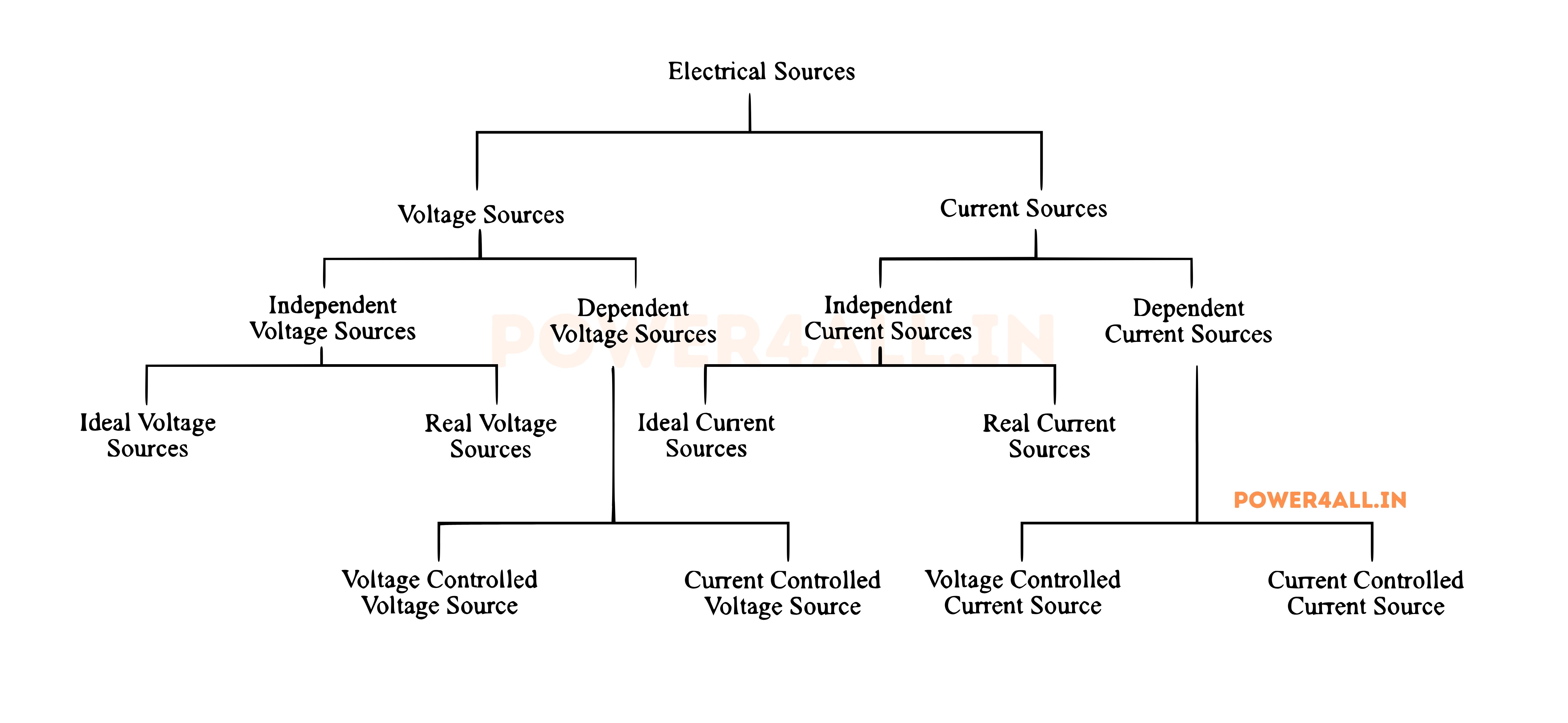
Primary Voltage Sources
Chemical Batteries
Principle: Chemical energy converted to electrical energy
Primary Batteries (Non-rechargeable)
- Alkaline: 1.5V, long shelf life, general purpose
- Lithium: 3V, excellent in extreme temperatures
- Zinc-carbon: 1.5V, economical, low drain devices
- Silver oxide: 1.55V, stable voltage, watches
Secondary Batteries (Rechargeable)
- Lead-acid: 2V/cell, automotive, UPS systems
- Lithium-ion: 3.7V/cell, high energy density
- NiMH: 1.2V/cell, hybrid vehicles
- LiFePO4: 3.2V/cell, long cycle life, safety
Solar Cells (Photovoltaic)
Principle: Light energy converted to electrical energy
Cell Technologies
- Monocrystalline: 0.6V/cell, highest efficiency (~22%)
- Polycrystalline: 0.6V/cell, good efficiency (~18%)
- Thin-film: 0.6V/cell, flexible, lower cost
- Perovskite: Emerging technology, high potential
System Configurations
- Grid-tied: Connected to utility grid
- Off-grid: Battery storage systems
- Hybrid: Grid connection with backup
- Microinverters: Individual panel optimization
Generators (Electromagnetic)
Principle: Mechanical energy converted to electrical energy
AC Generators (Alternators)
- Synchronous: Fixed speed, power grid applications
- Induction: Variable speed, wind turbines
- Permanent magnet: High efficiency, small size
- Wound field: Controllable excitation
DC Generators
- Separately excited: External field supply
- Self-excited: Series, shunt, or compound
- Permanent magnet: Simple, maintenance-free
- Applications: Welding, electric vehicles
Electronic Voltage Sources
Power Supplies and Converters
Linear Power Supplies
Operation: Continuous voltage regulation using linear devices
- Transformer: Steps down AC voltage
- Rectifier: Converts AC to pulsating DC
- Filter: Smooths voltage ripple
- Regulator: Maintains constant output
Advantages
- Low noise and ripple
- Fast transient response
- Simple design
- No electromagnetic interference
Disadvantages
- Low efficiency (60-70%)
- Heat generation
- Large and heavy
- Limited input voltage range
Switching Power Supplies
Operation: High-frequency switching for voltage conversion
- Switching element: MOSFET or IGBT
- Inductor/Transformer: Energy storage/transfer
- Control circuit: PWM feedback control
- Output filter: Smooths switched output
Advantages
- High efficiency (85-95%)
- Compact and lightweight
- Wide input voltage range
- Cost-effective
Disadvantages
- Switching noise
- Complex design
- EMI generation
- Slower transient response
DC-DC Converter Topologies
| Topology | Voltage Relationship | Isolation | Efficiency | Applications |
|---|---|---|---|---|
| Buck (Step-down) | Vout < Vin | No | 90-95% | CPU power, LED drivers |
| Boost (Step-up) | Vout > Vin | No | 90-95% | Battery-powered devices |
| Buck-Boost | Vout ≠ Vin | No | 85-90% | Battery backup systems |
| Flyback | Variable | Yes | 80-85% | Low-power isolated supplies |
| Forward | Variable | Yes | 85-90% | Medium-power supplies |
Alternative and Emerging Sources
Thermoelectric Generators
Convert temperature differences directly to voltage using the Seebeck effect. Applications include waste heat recovery and remote sensing.
Fuel Cells
Convert chemical energy of hydrogen directly to electricity with high efficiency and water as the only byproduct.
Piezoelectric Generators
Generate voltage from mechanical stress or vibration. Used in energy harvesting from motion, vibration, and pressure.
RF Energy Harvesting
Capture ambient radio frequency energy and convert it to usable DC voltage for low-power wireless devices.
Voltage Source Selection Criteria
- Power requirements: Voltage level, current capacity, power rating
- Regulation: Acceptable voltage variation under load changes
- Efficiency: Energy conversion efficiency requirements
- Isolation: Need for electrical isolation from input
- Size/weight: Physical constraints and portability
- Cost: Initial cost and operating expenses
- Reliability: Lifetime and maintenance requirements
- Environment: Temperature, humidity, vibration tolerance
Measuring Voltage: Tools and Techniques
Accurate voltage measurement is fundamental to electrical work, troubleshooting, and circuit analysis. Understanding measurement tools, techniques, and safety procedures ensures reliable results and personal safety.
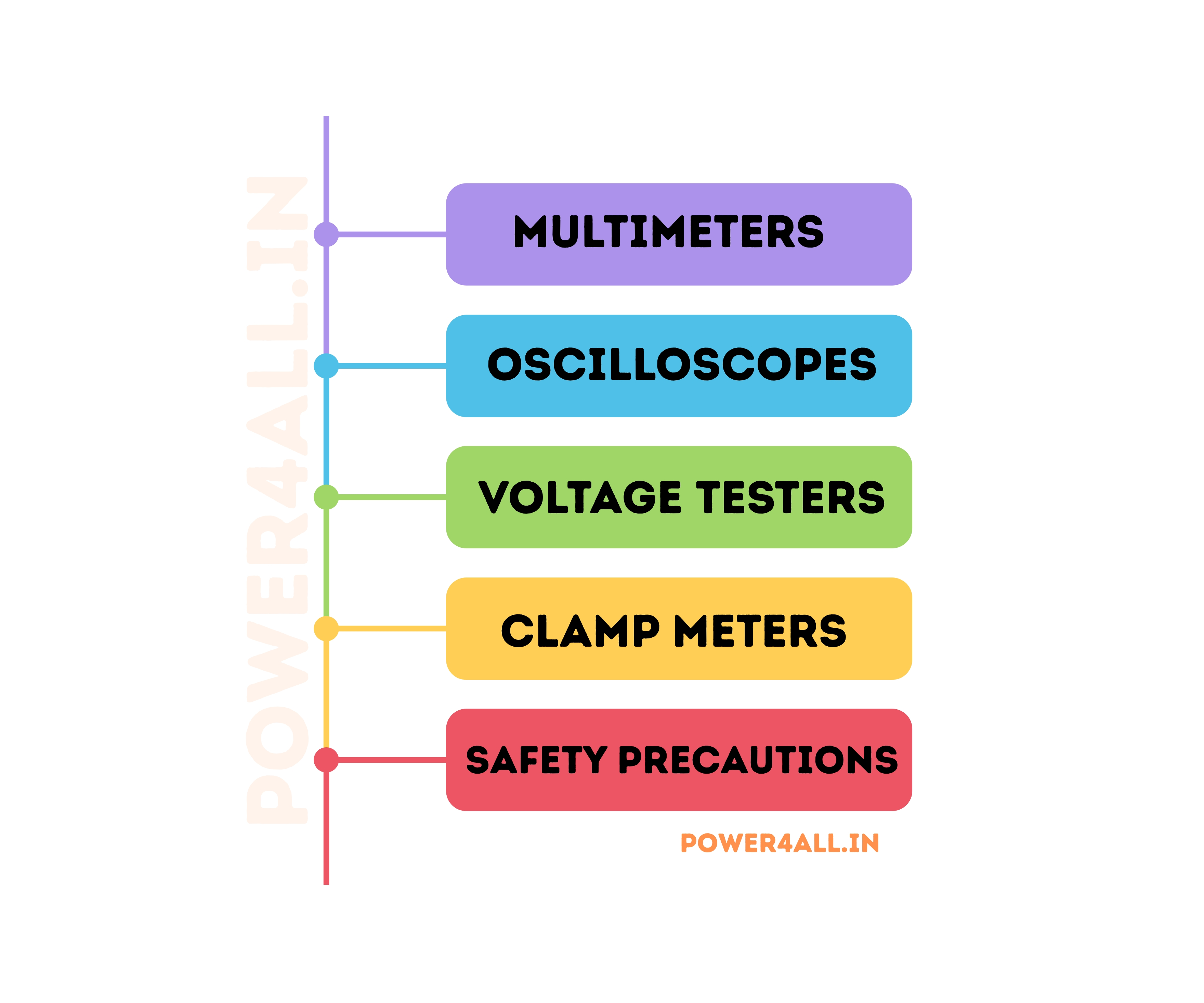
Voltage Measurement Instruments
Digital Multimeters (DMM)
Most common voltage measurement tool
Key Specifications
- Accuracy: ±0.1% to ±3% of reading
- Resolution: 3.5 to 8.5 digits display
- Input impedance: 10MΩ typical for voltage
- Bandwidth: DC to several kHz for AC
- Safety rating: CAT I/II/III/IV classifications
Measurement Capabilities
- DC voltage: 200mV to 1000V ranges
- AC voltage: True RMS or average responding
- Frequency: Built-in frequency counter
- Other functions: Current, resistance, continuity
Oscilloscopes
Visual voltage measurement and waveform analysis
Advantages
- Waveform display: See voltage vs. time
- High bandwidth: MHz to GHz frequencies
- Multiple channels: Compare multiple signals
- Triggering: Capture specific events
- Storage: Digital storage oscilloscopes
Measurement Features
- Peak-to-peak voltage: Maximum voltage swing
- RMS calculations: Automatic RMS measurements
- Rise/fall time: Signal transition analysis
- Frequency analysis: FFT capabilities
Specialized Meters
Purpose-built voltage measurement instruments
Analog Volt Meters
- Moving coil: DC voltage measurement
- Moving iron: AC voltage measurement
- Electrodynamic: Precision AC/DC measurement
- Advantages: Fast response, no power required
High-Voltage Meters
- Electrostatic: Very high voltage measurement
- Capacitive dividers: Non-contact measurement
- Optical isolation: Safety in HV applications
- Range: kV to MV measurements
Measurement Techniques and Best Practices
Proper Measurement Procedures
Basic Voltage Measurement Steps
Safety First
Always observe safety procedures:
- Turn off power when possible before connecting meters
- Use meters rated for the voltage being measured
- Inspect probes and leads for damage before use
- Keep one hand behind back when measuring high voltages
- Use appropriate PPE (personal protective equipment)
Common Measurement Errors
| Error Type | Cause | Effect | Prevention |
|---|---|---|---|
| Loading Error | Low meter input impedance | Reduced voltage reading | Use high-impedance meters (10MΩ+) |
| Probe Compensation | Mismatched probe capacitance | Frequency response errors | Properly compensate oscilloscope probes |
| Ground Loops | Multiple ground connections | Noise and interference | Use differential measurements |
| Range Selection | Inappropriate voltage range | Poor resolution or overload | Select range just above expected value |
AC Voltage Measurement Considerations
AC Voltage Measurement Challenges
True RMS vs Average Responding
True RMS Meters
- Accuracy: Correct for any waveform shape
- Applications: Non-sinusoidal waveforms, harmonics
- Cost: More expensive than average responding
- Crest factor: Handles high peak-to-RMS ratios
Average Responding
- Calibration: Scaled for sine wave RMS
- Accuracy: ±1% for pure sine waves only
- Error: Significant error with distorted waveforms
- Cost: Less expensive, basic meters
Waveform Factor Corrections
Average responding meters show incorrect readings for non-sinusoidal waveforms:
- Square wave: 11% higher reading than true RMS
- Triangle wave: 4% higher reading than true RMS
- Distorted sine: Error depends on harmonic content
- Pure sine wave: Correct reading (calibrated reference)
Frequency Response Limitations
Bandwidth Considerations
Different instruments have different frequency limitations:
- Basic DMM: DC to 1kHz typical
- True RMS DMM: DC to 10kHz typical
- AC voltmeter: 20Hz to 100kHz typical
- Oscilloscope: DC to several GHz possible
Measurement Safety Categories
| Safety Category | Application | Voltage Rating | Installation Type | Example Locations |
|---|---|---|---|---|
| CAT I | Protected circuits | Up to 1000V | Equipment level | Electronics, protected equipment |
| CAT II | Local distribution | Up to 1000V | Equipment level | Appliances, portable equipment |
| CAT III | Distribution panels | Up to 1000V | Installation level | Panel boards, motor circuits |
| CAT IV | Primary supply | Up to 1000V | Utility level | Service entrance, utility meters |
Voltage in Circuits: Analysis and Applications
Understanding how voltage behaves in different circuit configurations is essential for circuit analysis, design, and troubleshooting. Voltage distribution follows specific laws that govern all electrical circuits.
Kirchhoff's Voltage Law (KVL)
∑V = 0
The algebraic sum of all voltages around any closed loop equals zero
Understanding KVL
Physical Meaning
KVL is based on conservation of energy. When you start at any point in a circuit and travel around a complete loop back to the starting point, the net energy change must be zero.
Simple KVL Example
Circuit: 12V battery with 8Ω and 4Ω resistors in series
Current: I = 12V/(8Ω + 4Ω) = 1A
Voltage drops:
- V₁ = 1A × 8Ω = 8V
- V₂ = 1A × 4Ω = 4V
KVL check: +12V - 8V - 4V = 0 ✓
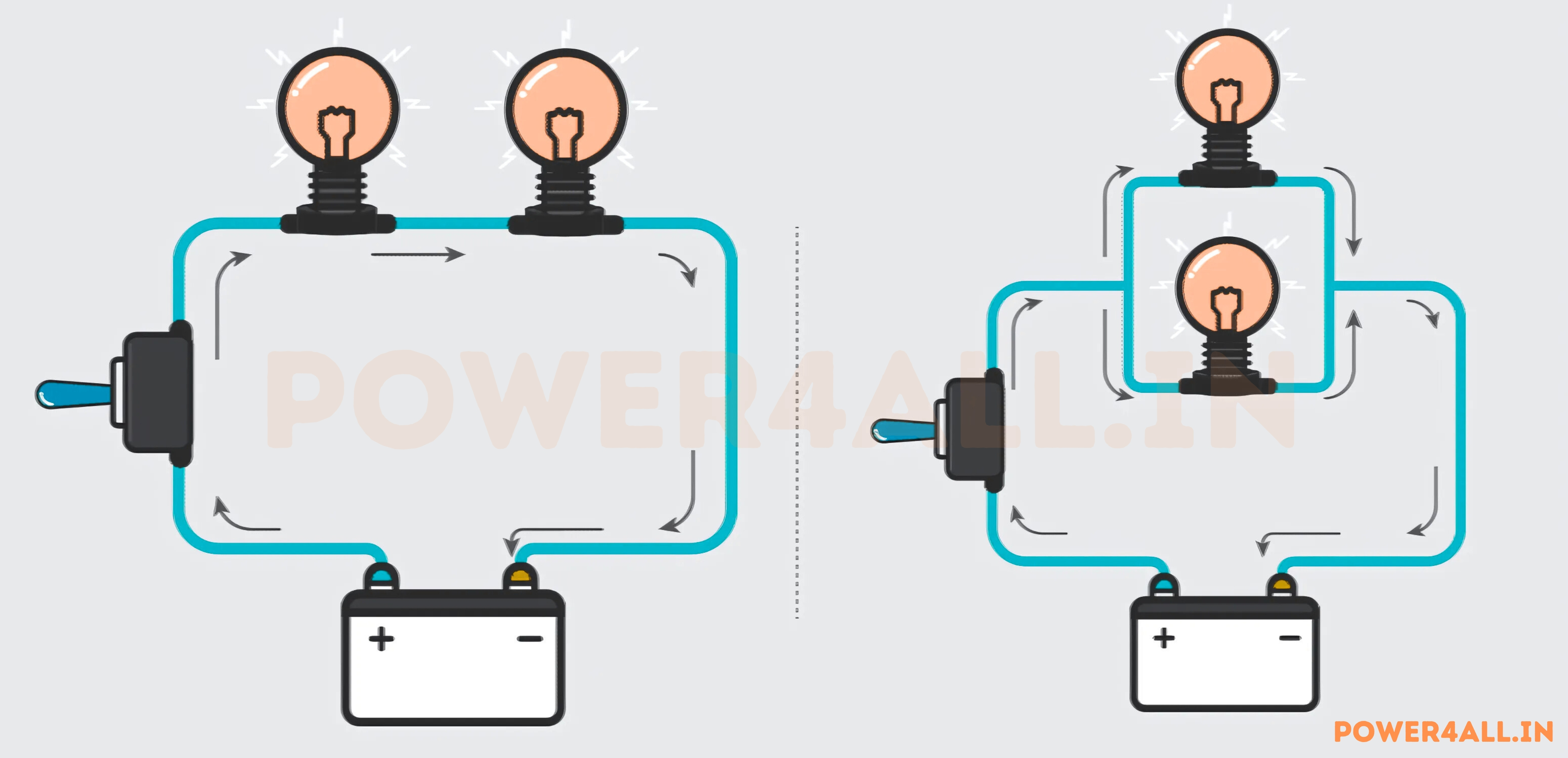
Series Circuits: Voltage Division
Voltage Division in Series Circuits
In series circuits, voltage divides proportionally among components based on their resistance values. This fundamental principle enables countless circuit applications from simple voltage references to complex sensor networks.
Voltage Divider Formula
V_out = V_in × (R2 / (R1 + R2))
Output voltage in a two-resistor voltage divider
Series Circuit Characteristics
Same Current
All components in series carry identical current. Current is determined by total voltage and total resistance.
Voltage Addition
Individual voltage drops add up to equal the supply voltage. This satisfies Kirchhoff's Voltage Law.
Proportional Division
Larger resistances receive proportionally larger voltage drops. This enables precise voltage scaling.
Practical Voltage Divider Example
Circuit: 12V supply with 10kΩ and 5kΩ resistors in series
Total resistance: Rtotal = 10kΩ + 5kΩ = 15kΩ
Current: I = 12V / 15kΩ = 0.8mA
Voltage drops:
- V₁ (across 10kΩ) = 0.8mA × 10kΩ = 8V
- V₂ (across 5kΩ) = 0.8mA × 5kΩ = 4V
- Check: 8V + 4V = 12V ✓
Applications: Sensor biasing, reference voltages, analog-to-digital conversion
Loading Effects
Important Consideration
Voltage dividers work accurately only when the load resistance is much higher than the divider resistances. Low load resistance will "load down" the divider, reducing output voltage.
Rule of thumb: Load resistance should be at least 10× larger than the divider's equivalent resistance.
Parallel Circuits: Voltage Distribution
Voltage Behavior in Parallel Circuits
In parallel circuits, all components share the same voltage while currents divide based on individual resistances. This configuration is fundamental to power distribution systems.
Parallel Circuit Characteristics
Equal Voltages
All parallel branches have identical voltage across them, equal to the supply voltage.
- Kirchhoff's Voltage Law: All parallel paths have same potential difference
- Independent operation: Each branch operates independently
- Failure isolation: One branch failure doesn't affect others
Current Division
Total current divides among branches inversely proportional to their resistances.
- Lower resistance: Draws more current
- Current calculation: I = V/R for each branch
- Total current: Sum of all branch currents
I_total = I₁ + I₂ + I₃ + ... + Iₙ
Total current equals sum of branch currents
Household Electrical System Example
Voltage: 120V AC supply to all outlets
Devices in parallel:
- 100W light bulb: I = 100W/120V = 0.83A
- 1500W microwave: I = 1500W/120V = 12.5A
- 200W computer: I = 200W/120V = 1.67A
- Total current: 0.83A + 12.5A + 1.67A = 15A
Circuit breaker rating: 20A (provides safety margin)
Common Voltage Levels: Understanding Standards
Voltage levels are standardized across different applications to ensure safety, compatibility, and efficiency. Understanding these standards is essential for proper system design and safe operation.
Safety Voltage Classifications
| Classification | Voltage Range (DC) | Voltage Range (AC RMS) | Safety Level | Typical Applications | Protection Required |
|---|---|---|---|---|---|
| Extra-Low Voltage (ELV) | ≤ 120V DC | ≤ 50V AC | Safe to touch | Electronics, control circuits, LED lighting | Basic insulation |
| Low Voltage (LV) | 120V - 1500V DC | 50V - 1000V AC | Can cause shock | Household, commercial, small industrial | GFCI, proper grounding |
| Medium Voltage (MV) | 1.5kV - 35kV DC | 1kV - 35kV AC | Dangerous | Distribution systems, large motors | Switchgear, trained personnel |
| High Voltage (HV) | 35kV - 100kV DC | 35kV - 100kV AC | Lethal | Transmission lines, substations | Specialized equipment, clearances |
| Extra-High Voltage (EHV) | > 100kV DC | > 100kV AC | Extremely lethal | Long-distance transmission | Extensive safety systems |
Worldwide Power System Standards
Residential Power Systems
North America
- Single-phase: 120V, 60Hz (outlets, lighting)
- Split-phase: 240V, 60Hz (dryers, stoves, AC)
- Service entrance: 120V/240V, 100A-400A typical
Europe/Asia/Africa
- Single-phase: 230V, 50Hz (most outlets)
- Three-phase: 400V, 50Hz (high-power appliances)
- Tolerance: ±10% voltage variation allowed
Other Regional Standards
- Japan: 100V, 50Hz (east) / 60Hz (west)
- Brazil: 127V/220V, 60Hz
- Australia: 230V, 50Hz
Commercial & Industrial Systems
Low Voltage Distribution
- 208V Three-phase: Small commercial buildings
- 480V Three-phase: Industrial facilities, large HVAC
- 600V Systems: Canadian industrial standard
Medium Voltage Distribution
- 4.16kV: Large industrial facilities
- 13.8kV: Commercial distribution
- 25kV: Utility distribution feeders
Power Quality Standards
- Voltage regulation: ±5% steady-state
- Harmonic distortion: <5% THD typical
- Power factor: >0.9 required for large loads
Electronic System Voltages
Digital Logic Levels
- 5V TTL: Traditional digital circuits
- 3.3V CMOS: Modern microcontrollers, FPGAs
- 1.8V/1.2V: Advanced processors, memory
- Differential: LVDS, CML for high-speed signals
Power Supply Rails
- +12V: Motors, fans, analog circuits
- +5V: Legacy digital, USB power
- +3.3V: Modern digital systems
- ±15V: Op-amps, analog circuits
- Negative voltages: -5V, -12V for specialized circuits
Battery-Powered Systems
- 1.5V: AA, AAA alkaline batteries
- 3.7V: Lithium-ion cells
- 9V: Transistor batteries
- 12V: Automotive, UPS systems
Voltage Level Selection Criteria
Factors Influencing Voltage Choice
Power Transmission Efficiency
Higher voltages reduce transmission losses by reducing current for the same power:
P_loss = I² × R_line
Power loss is proportional to current squared
Transmission Loss Comparison
Load: 1MW over 10km line (R = 1Ω total)
- At 1kV: I = 1000A, Loss = 1000² × 1 = 1MW (100%!)
- At 10kV: I = 100A, Loss = 100² × 1 = 10kW (1%)
- At 100kV: I = 10A, Loss = 10² × 1 = 0.1kW (0.01%)
This demonstrates why long-distance transmission uses very high voltages.
Safety Considerations
Touch Safety
Voltages below 50V AC / 120V DC are generally considered safe to touch under normal conditions.
Arc Flash Risk
Higher voltages can sustain dangerous arcs. Arc flash studies required for systems >480V.
Clearance Requirements
Minimum air gaps and creepage distances increase with voltage to prevent flashover.
Economic Factors
- Equipment cost: Higher voltage equipment is more expensive
- Installation cost: Higher voltages require specialized installation
- Operating efficiency: Higher voltages reduce energy losses
- Maintenance requirements: Specialized training and equipment needed
Voltage Safety: Critical Protection Measures
Electrical safety is paramount when working with voltage. Understanding hazards, safety procedures, and protection devices can prevent injury, death, and property damage. Safety must never be compromised for convenience or speed.
Critical Safety Warning
Electricity can kill instantly and silently. Even experienced electricians can be seriously injured or killed by electrical accidents. Always follow proper safety procedures, use appropriate PPE, and when in doubt, consult a qualified professional.
Understanding Electrical Hazards
Physiological Effects of Electric Current
Current Levels and Human Response
| Current Level | Physiological Effect | Duration Tolerance | Safety Implications |
|---|---|---|---|
| 1 mA | Barely perceptible | Indefinite | Generally safe threshold |
| 5 mA | Maximum "safe" current | Indefinite | GFCI trip threshold |
| 10-20 mA | Muscular control lost | Minutes | Cannot let go of conductor |
| 50 mA | Ventricular fibrillation possible | Seconds | Potentially lethal |
| 100-200 mA | Certain ventricular fibrillation | Instant | Usually fatal |
| > 200 mA | Severe burns, muscle contraction | Instant | Massive tissue damage |
Key Understanding
It's current through the body, not voltage, that causes injury. However, higher voltages can drive larger currents through body resistance. Voltage determines current: I = V / R_body.
Electrical Fire Hazards
Common Causes
- Overloaded circuits: Current exceeds wire capacity
- Poor connections: High resistance causes heating
- Damaged insulation: Arcing and short circuits
- Arc faults: Sustained arcs ignite surroundings
Prevention Measures
- Proper circuit protection: Breakers, fuses sized correctly
- Arc fault circuit interrupters (AFCI): Detect dangerous arcs
- Regular inspection: Check for damaged wiring
- Load calculation: Don't exceed circuit capacity
Fire Power Calculation
Scenario: Loose connection with 0.5Ω resistance, 15A load
Power dissipated: P = I²R = 15² × 0.5 = 112.5W
Heat generation: Enough to ignite most materials
Prevention: Proper torque on connections, quality components
Arc Flash and Blast Hazards
Arc Flash Characteristics
- Temperature: 35,000°F (19,400°C) - hotter than sun's surface
- Light intensity: Can cause permanent eye damage
- Sound pressure: Can rupture eardrums
- Pressure wave: Can knock people down
Arc Flash Energy Calculation
E = 4.184 × Cf × En × (t/0.2) × (610ˣ/D²)
Arc flash incident energy (cal/cm²)
Protection Strategies
- De-energize when possible: Lockout/tagout procedures
- Remote operation: Operate switches from safe distance
- Arc-resistant equipment: Designed to contain arc energy
- Personal protective equipment: Arc-rated clothing and equipment
Essential Safety Procedures
Lockout/Tagout (LOTO) Procedures
LOTO procedures prevent accidental energization during maintenance work. These procedures are legally required in many jurisdictions and have saved countless lives.
Six-Step LOTO Process
Lock and Tag Requirements
Locks
Physical devices that prevent operation. Each worker applies their own lock. Only the person who applied the lock can remove it.
Tags
Information devices explaining why equipment is locked out. Include date, reason, authorized person, and expected completion.
Group Lockout
When multiple workers are involved, use group lockout boxes where each worker applies their personal lock to a common container.
Critical Rule
Never remove another person's lock. Even supervisors and maintenance managers must not remove locks applied by others. The person who applied the lock is the only one authorized to remove it.
Protective Devices and Systems
Ground Fault Circuit Interrupters (GFCI)
Function: Detect ground faults and interrupt current flow
- Trip threshold: 4-6 mA current imbalance
- Response time: < 25 milliseconds
- Protection: Prevents electrocution from ground faults
- Testing: Monthly test/reset required
- Applications: Bathrooms, kitchens, outdoor outlets
Arc Fault Circuit Interrupters (AFCI)
Function: Detect dangerous arcing conditions
- Detection: Parallel and series arc faults
- Response time: < 0.5 seconds
- Protection: Prevents fires from arc faults
- Testing: Monthly test button check
- Applications: Bedrooms, living areas (NEC required)
Surge Protection Devices (SPD)
Function: Protect against voltage spikes and surges
- Response time: Nanoseconds
- Protection levels: Type 1, 2, and 3 devices
- Clamping voltage: 330V-2000V typical
- Energy rating: Joules of surge energy absorbed
- Applications: Whole house, panel, and device protection
Practical Applications of Voltage
Voltage enables countless applications that power our modern world. From the smallest electronic devices to massive industrial systems, understanding these applications helps in selecting appropriate voltage sources and designing efficient systems.
Consumer Electronics and Appliances
Mobile Devices
Voltage Requirements: 3.7V Li-ion battery, 5V USB charging
Key Voltage Rails
- Battery voltage: 3.0V - 4.2V (Li-ion)
- Processor core: 0.8V - 1.2V (ultra-low power)
- Memory (RAM): 1.2V - 1.8V
- Display/Radio: 2.8V - 3.3V
- USB charging: 5V (USB-A) to 20V (USB-C PD)
Power Management Challenges
- Efficiency: >90% to maximize battery life
- Heat generation: Thermal throttling in compact space
- Fast charging: 18W-100W+ charging speeds
- Multiple rails: 10+ different voltage levels needed
Household Appliances
Voltage Requirements: 120V/240V AC mains power
Major Appliances
- Refrigerator: 120V, 3-5A (compressor motor)
- Electric dryer: 240V, 30A (heating elements)
- Air conditioner: 240V, 20-50A (large motors)
- Electric range: 240V, 40-50A (heating elements)
- Water heater: 240V, 20-30A (resistance heating)
Small Appliances
- Microwave: 120V, 10-15A (magnetron)
- Toaster: 120V, 8-12A (heating elements)
- Coffee maker: 120V, 8-10A (heating plate)
- Hair dryer: 120V, 12-15A (motor + heater)
Entertainment Systems
Voltage Requirements: Various DC levels from AC adapters
Audio/Video Equipment
- LED TV: 12V internal (from AC adapter)
- Sound system: ±15V (analog audio stages)
- Gaming console: 12V (from external PSU)
- Router/modem: 5V-12V (low power)
- Speakers: Variable (amplifier dependent)
Power Efficiency Standards
- Energy Star: <0.5W standby power
- Power factor: >0.9 for >25W equipment
- Harmonic limits: IEC 61000-3-2 compliance
- Efficiency: >80% for external adapters
Industrial and Commercial Applications
Industrial Power Systems
Motor Drives
Voltage Levels: 208V, 480V, 600V three-phase
- Small motors: 208V, 1-5 HP
- Medium motors: 480V, 5-200 HP
- Large motors: 4160V, 200-5000 HP
- Variable frequency drives: Energy savings 20-50%
Power Distribution
Voltage Levels: Multi-level distribution systems
- Utility feed: 13.8kV - 34.5kV
- Plant distribution: 4.16kV - 13.8kV
- Equipment supply: 208V - 600V
- Control circuits: 24V - 120V DC/AC
Process Control
Voltage Levels: Low voltage DC for precision
- Sensor supply: 24V DC (industry standard)
- Analog signals: 0-10V, ±10V
- Digital I/O: 24V DC (robust, noise immune)
- Communication: 5V, 3.3V (fieldbus systems)
Industrial Voltage Standards
| Application | Voltage Level | Frequency | Power Range | Typical Uses |
|---|---|---|---|---|
| Control Systems | 24V DC | DC | 1W - 100W | PLCs, sensors, actuators |
| Small Motors | 208V, 3-phase | 60Hz | 1-10 HP | Pumps, fans, conveyors |
| Medium Motors | 480V, 3-phase | 60Hz | 10-500 HP | Compressors, mills, mixers |
| Large Motors | 4160V, 3-phase | 60Hz | 500-5000 HP | Crushers, large pumps |
| Arc Furnaces | 13.8kV - 34.5kV | 60Hz | 1-100 MW | Steel melting, aluminum production |
Voltage Troubleshooting Guide
Effective voltage troubleshooting requires systematic approaches, proper tools, and understanding of common problems. This guide helps diagnose and resolve voltage-related issues safely and efficiently.
Common Voltage Problems
| Problem | Symptoms | Likely Causes | Diagnostic Steps | Solutions |
|---|---|---|---|---|
| No Voltage | Complete power loss | Open circuit, blown fuse, tripped breaker | Check continuity, inspect connections | Repair open, replace fuse/reset breaker |
| Low Voltage | Dim lights, slow motors | High resistance, voltage drop, overload | Measure voltage under load | Improve connections, upgrade conductors |
| High Voltage | Bright lights, equipment damage | Regulator failure, open neutral | Check regulation, neutral integrity | Repair regulator, fix neutral connection |
| Voltage Fluctuation | Flickering, intermittent operation | Loose connections, poor regulation | Monitor voltage over time | Tighten connections, improve regulation |
| Voltage Imbalance | Uneven three-phase voltages | Unbalanced loads, phase loss | Measure all three phases | Balance loads, repair phase conductor |
Systematic Troubleshooting Approach
Voltage Drop Troubleshooting
Identifying and Solving Voltage Drop Issues
Acceptable Voltage Drop Limits
- Branch circuits: 3% maximum from panel to outlet
- Feeder circuits: 3% maximum from service to panel
- Total system: 5% maximum from service to outlet
- Motor circuits: 5% maximum during starting
Voltage Drop = I × R × L × 2
For single-phase circuits (multiply by 1.732 for three-phase)
Voltage Drop Calculation Example
Circuit: 20A load, 100ft run, 12 AWG copper wire (R = 1.59Ω/1000ft)
Calculation: VD = 20A × 1.59Ω/1000ft × 100ft × 2 = 6.36V
Percentage: 6.36V / 120V = 5.3% (exceeds 3% limit)
Solution: Use 10 AWG wire (R = 1.0Ω/1000ft) for 4.0V drop (3.3%)
Solutions for Excessive Voltage Drop
Increase Wire Size
Use larger conductor to reduce resistance and voltage drop.
Increase Voltage
Use higher voltage supply to reduce current for same power.
Reduce Distance
Relocate loads closer to power source when possible.
Multiple Circuits
Divide load among multiple smaller circuits.
Voltage Regulation: Maintaining Stable Voltage
Voltage regulation maintains stable voltage levels despite varying loads and input conditions. Good regulation is essential for proper equipment operation, energy efficiency, and preventing damage from voltage variations.
Types of Voltage Regulation
Linear Voltage Regulators
Operation: Continuous control using linear pass element
Characteristics
- Regulation: Excellent (±0.1% typical)
- Response time: Very fast (microseconds)
- Noise: Very low output noise
- Efficiency: Poor (50-70%)
- Heat generation: High (requires heat sinking)
Applications
- Precision analog circuits
- Low-power applications
- Noise-sensitive circuits
- Reference voltage sources
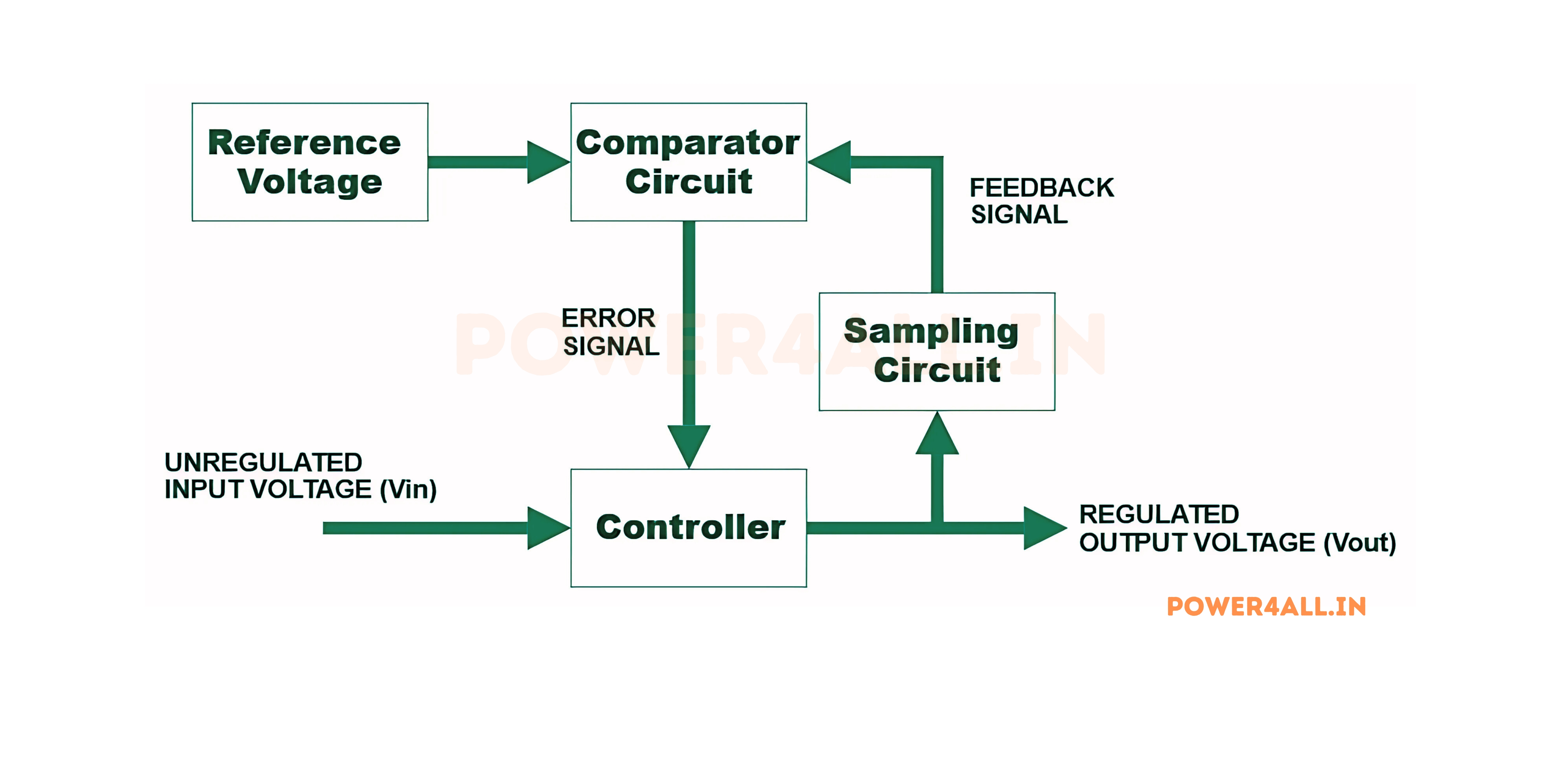
Switching Voltage Regulators
Operation: High-frequency switching with feedback control
Characteristics
- Regulation: Good (±1-3% typical)
- Response time: Moderate (milliseconds)
- Noise: Higher switching noise
- Efficiency: Excellent (85-95%)
- Heat generation: Low
Applications
- Computer power supplies
- Battery-powered devices
- High-power applications
- DC-DC converters
Automatic Voltage Regulators (AVR)
Operation: Feedback control of generator excitation
Characteristics
- Regulation: Good (±2-5% typical)
- Response time: Slow (seconds)
- Power range: Very high (MW)
- Reliability: High
- Maintenance: Moderate
Applications
- Power plant generators
- Standby generators
- Marine generators
- Industrial generators
Power System Voltage Regulation
Utility Grid Voltage Regulation Methods
Voltage Regulation Equipment
| Equipment | Voltage Range | Response Time | Regulation Range | Applications |
|---|---|---|---|---|
| Load Tap Changers | Distribution/Transmission | 30-60 seconds | ±10% (32 steps) | Substation transformers |
| Voltage Regulators | Distribution | 30-60 seconds | ±10% (32 steps) | Feeder voltage control |
| Capacitor Banks | Distribution | Minutes | Variable (steps) | Reactive power compensation |
| Static VAR Compensators | Transmission | Cycles | Continuous | Dynamic voltage support |
| STATCOM | Transmission | Milliseconds | Continuous | Fast voltage regulation |
Voltage Regulation Hierarchy
Voltage Regulation Standards
- ANSI C84.1: ±5% voltage range for normal operation
- Range A: 114V-126V (120V nominal), preferred range
- Range B: 110V-127V (120V nominal), tolerable range
- Service voltage: Voltage at customer's service entrance
- Utilization voltage: Voltage at customer's equipment
Voltage Regulation Performance Metrics
Regulation Percentage
Regulation % = (VNL - VFL) / VFL × 100, where VNL = no-load voltage, VFL = full-load voltage
Response Time
Time required to restore voltage to within acceptable limits after a disturbance
Accuracy
How closely the regulated voltage matches the desired setpoint under steady-state conditions
Stability
Ability to maintain stable voltage without oscillation or hunting around the setpoint
Frequently Asked Questions
Common questions about voltage answered by experts, covering fundamentals, applications, safety, and practical considerations.
Basic Voltage Questions
What exactly is voltage and why is it important?
Voltage is the electric potential difference between two points, representing the energy available per unit charge. It's the "electrical pressure" that drives current through circuits, making all electrical devices possible.
Key Points About Voltage
- Definition: Work done per unit charge (Joules per Coulomb)
- Measurement: Always between two points, never at a single point
- Role: Provides the driving force for electric current
- Unit: Volt (V), named after Alessandro Volta
- Analogy: Like water pressure in a plumbing system
What's the difference between AC and DC voltage?
DC voltage maintains constant magnitude and polarity, while AC voltage continuously changes both magnitude and direction in a cyclical pattern.
| Characteristic | DC Voltage | AC Voltage |
|---|---|---|
| Waveform | Straight line (constant) | Sine wave (varying) |
| Polarity | Fixed (+ and - don't change) | Alternating (+ and - switch) |
| Frequency | 0 Hz (no frequency) | 50/60 Hz (power), various (signals) |
| Transmission | Difficult over long distances | Easy with transformers |
| Storage | Direct storage in batteries | Must convert to DC for storage |
What's the relationship between voltage and current?
Voltage and current are related through Ohm's Law: V = I × R. Voltage is the driving force, current is the flow of charge, and resistance opposes the flow.
V = I × R
Voltage = Current × Resistance
Understanding the Relationship
- Voltage: Electrical pressure (like water pressure)
- Current: Flow of electrons (like water flow rate)
- Resistance: Opposition to flow (like pipe friction)
- Higher voltage: Can push more current through same resistance
- Higher resistance: Reduces current for same voltage
Safety and Practical Questions
At what voltage level does electricity become dangerous?
Danger depends on both voltage and current. Generally, voltages above 50V AC or 120V DC are considered potentially dangerous, but even lower voltages can be hazardous under certain conditions.
Safety Guidelines
- 50V AC / 120V DC: Generally considered safe touch voltage limits
- Body resistance: Varies from 1,000Ω (wet) to 100,000Ω (dry)
- Current matters: 5mA is considered maximum safe current
- Path matters: Hand-to-hand more dangerous than hand-to-foot
- Conditions matter: Wet conditions greatly increase danger
Why do different countries use different household voltages?
Historical reasons and different engineering approaches led to voltage standards. Early electrical systems developed independently in different countries before international standards existed.
Historical Development
- USA (120V): Edison's original DC system was 110V, carried over to AC
- Europe (230V): Higher voltage chosen for better efficiency
- Japan (100V): Adopted US system but lower voltage
- Advantages of 230V: Lower current, smaller wires, better efficiency
- Advantages of 120V: Considered safer, less insulation required
How do I properly measure voltage?
Voltage is measured across components (in parallel) using a voltmeter or multimeter. Always observe safety procedures and use appropriate measurement ranges.
Technical and Application Questions
What causes voltage drop and how can it be minimized?
Voltage drop is caused by current flowing through resistance in conductors and connections. It can be minimized by using larger wires, shorter runs, better connections, and higher voltages.
Larger Conductors
Bigger wires have less resistance, reducing voltage drop for same current.
Shorter Distances
Reduce wire length by placing loads closer to power source.
Higher Voltage
Higher voltage reduces current for same power, lowering I²R losses.
Better Connections
Tight, clean connections minimize resistance and voltage drop.
What are the most common voltage levels in different applications?
| Application | Voltage Level | Type | Examples |
|---|---|---|---|
| Consumer Electronics | 1.2V - 12V | DC | Phones, laptops, LED lights |
| Household Power | 120V/240V | AC | Outlets, appliances |
| Automotive | 12V/24V | DC | Cars, trucks, boats |
| Industrial Motors | 208V-480V | AC 3-phase | Pumps, fans, compressors |
| Power Distribution | 4kV-35kV | AC 3-phase | Substations, feeders |
| High Voltage Transmission | 100kV-800kV | AC 3-phase | Long-distance power lines |
Conclusion: Mastering Voltage for the Future
Voltage is the fundamental driving force behind all electrical phenomena, from the smallest electronic circuits to the largest power systems. Understanding voltage principles, measurement techniques, safety considerations, and applications is essential for anyone working with electrical systems.
Key Takeaways
Fundamental Understanding
Voltage is electric potential difference that drives current flow. It's measured between two points and represents energy per unit charge.
Safety First
Always prioritize safety when working with voltage. Use proper procedures, PPE, and measurement techniques to prevent injury.
Practical Applications
Voltage knowledge applies across all electrical fields, from consumer electronics to industrial power systems and emerging technologies.
Continuous Learning
Voltage technology continues evolving with smart grids, renewable energy, electric vehicles, and quantum applications.
Congratulations!
You've completed the comprehensive voltage guide. You now have a solid foundation in voltage principles, measurement techniques, safety procedures, and practical applications. Continue exploring and applying this knowledge in your electrical projects and career.