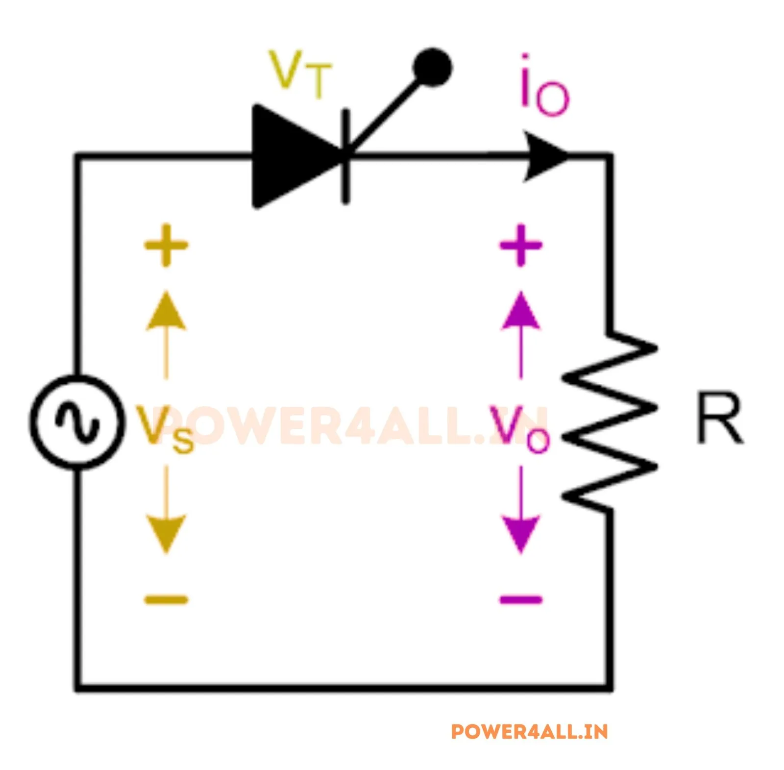
What is a single-phase half-wave controlled rectifier?
A single-phase half-wave controlled rectifier uses a single thyristor (SCR) in series with the load. During each positive half-cycle the SCR is triggered at a chosen firing angle α; it then conducts and passes the supply to the load until the current falls to zero. Because only one half of each cycle is used, the output is a train of single pulses — a simple, low-cost way to obtain a controllable DC from single-phase AC.
Output voltage equations (resistive load)
At α = 0 the SCR behaves like a diode and Vdc = Vm/π ≈ 0.318·Vm. As α increases, the conduction window shrinks and Vdc falls smoothly to zero at α = 180°. This simulator does not plug numbers into these formulas — it integrates the real circuit through the SCR's conduction states and measures Vdc and Vrms from the resulting samples, then compares them to the equations above in the accuracy panel.
Inductive load & the freewheeling diode
With an R-L load and no freewheeling diode, the inductor's stored energy keeps the SCR conducting past 180° into the negative half-cycle until the current reaches zero at the extinction angle β. This drags the output negative and lowers the average voltage. Adding a freewheeling diode across the load gives the current an alternative path when the supply goes negative: the diode clamps the output to zero, the SCR turns off at 180°, ripple falls and the average voltage rises back to (Vm/2π)(1+cos α). Toggle the freewheeling diode in the simulator to see the difference.
Adding an output filter
Half-wave output is highly pulsating (large ripple). A series inductor smooths the load current, a shunt capacitor holds the voltage near the peak and cuts ripple, and an LC filter combines both. The simulator integrates the real filter differential equations, so the Load ripple reading and the smoothed v₀ trace are physically exact.
Advanced options in this simulator
- SCR model: add a forward voltage drop
V_fand on-resistanceR_onto see the real (slightly lower) output — while the accuracy check stays locked to the ideal(Vm/2π)(1+cos α)envelope. - Transformer: a turns ratio scales the peak voltage
Vmapplied to the SCR. - Filter & protection: a series-L, shunt-C or LC output filter, an optional RC snubber, and a live protection-margin check of the SCR peak voltage (PIV vs V_RRM) and average current (vs I_T(av)).
- Harmonic spectrum analysis: a real FFT of the output voltage or load current, with the ripple / THD figure and a selectable number of harmonics.
- Export & capture: download the full waveform data as CSV, a text report of parameters and results, or a PNG screenshot of the scope.
Half-wave vs full-wave
| Feature | Half-wave controlled | Full-wave controlled |
|---|---|---|
| Devices | 1 SCR | 2–4 SCR |
| Average voltage | (Vm/2π)(1 + cos α) | (2Vm/π) cos α |
| Output pulses / cycle | 1 | 2 |
| Ripple | High | Lower |
| Transformer DC | Yes (core saturation risk) | No |
Applications
Small battery chargers, low-power DC supplies, light dimming, small heater and DC-motor speed control, and as a teaching example of phase control. For higher power and lower ripple a full-wave or bridge rectifier is preferred.
Frequently asked questions
What is the average output voltage of a half-wave controlled rectifier?
For a resistive load, Vdc = (Vm/2π)(1 + cos α). It is Vm/π at α = 0° and zero at α = 180°.
How does the firing angle control the output?
The firing angle α delays when the SCR is triggered in each positive half-cycle. A larger α shortens conduction, so the average output voltage decreases — this is phase control.
What does the freewheeling diode do?
With an inductive load it gives the load current a path when the supply reverses, clamping the output to zero, stopping the output from going negative, raising the average voltage and reducing ripple.
Why is half-wave rectification rarely used at high power?
It uses only one half of each cycle, giving high ripple, poor transformer utilisation and a DC component in the supply current that can saturate transformer cores. Full-wave rectifiers avoid these drawbacks.
What is the extinction angle β?
With an R-L load and no freewheeling diode, conduction continues past 180° until the inductor current falls to zero. That angle is the extinction angle β.
What does the harmonic spectrum show?
An FFT of the output voltage (or load current) into its DC value plus harmonics. Raising the firing angle α increases the harmonic content and the THD, shown live in the harmonic-spectrum panel. You can switch between the voltage and current spectra and choose how many harmonics to display.