Complete Resistor Mastery Guide
Master the fundamentals of resistors - from basic concepts and color codes to advanced applications in modern electronics and circuit design
Complete Learning Path - Resistor Fundamentals to Applications
Navigate through comprehensive coverage of resistors from basic principles to advanced applications
What is a Resistor?
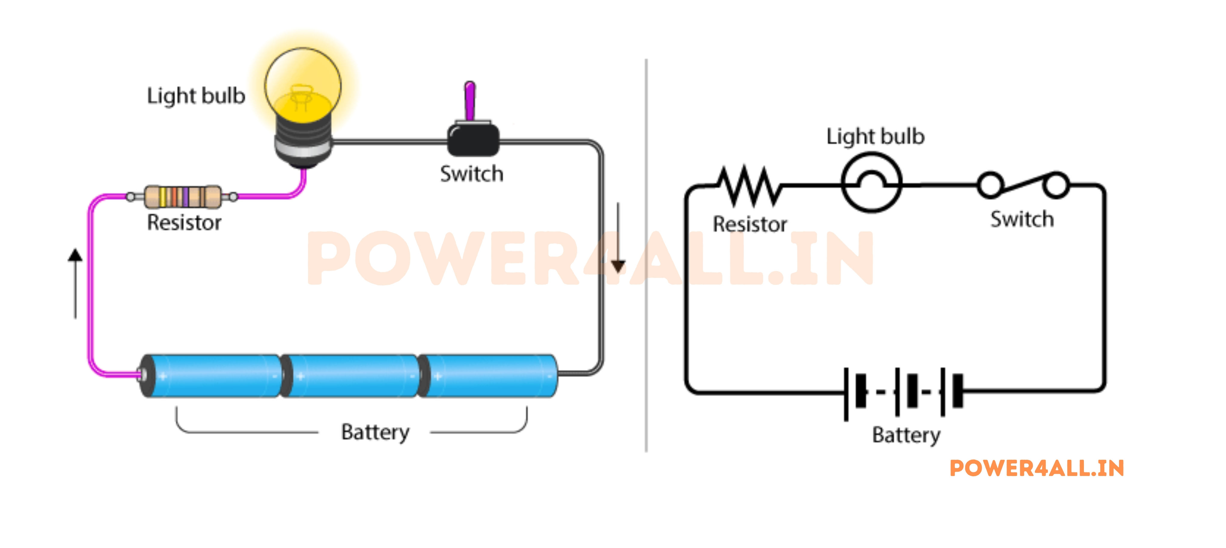
A resistor is a passive electronic component that opposes the flow of electric current, creating a voltage drop across its terminals. Think of it like a narrow section in a water pipe that restricts water flow - resistors do the same thing with electricity, and this property makes them one of the most fundamental and essential components in all electronic circuits.
The Water Pipe Analogy
Imagine water flowing through a pipe. If you place a narrow section in the pipe, it restricts the water flow and creates pressure differences. Similarly, a resistor restricts electrical current and creates voltage differences.
Perfect Comparison
- Water flow restriction → Current flow restriction
- Pipe narrowing → Resistor material property
- Pressure drop → Voltage drop across resistor
- Flow rate control → Current level control
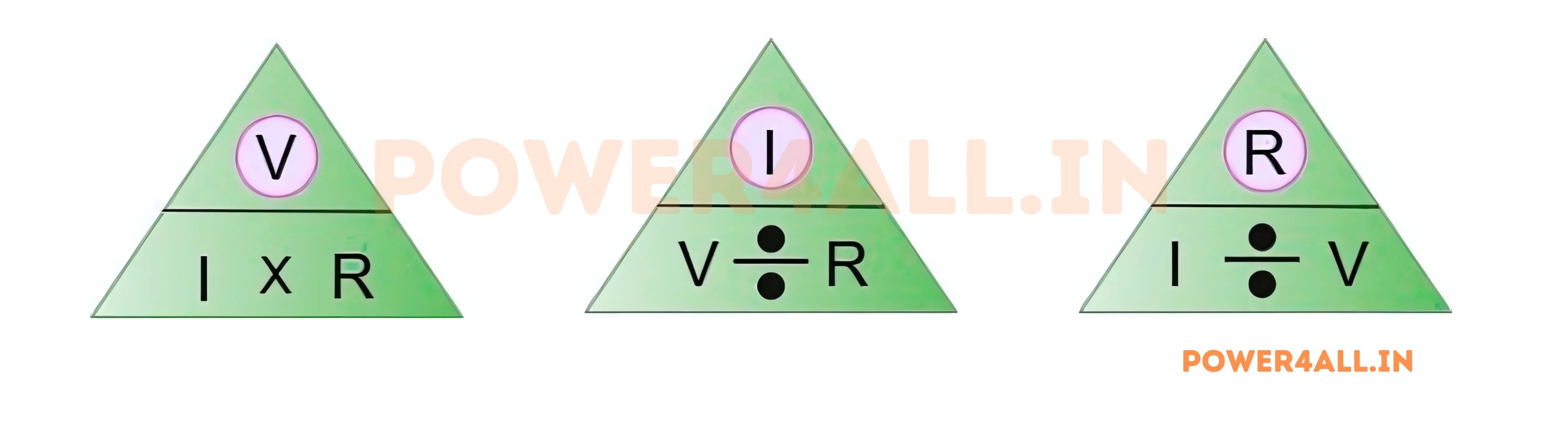
R = V / I
Resistance equals Voltage divided by Current (Ohm's Law)
Why Resistors are Essential
Resistors might seem like simple components that just "resist" current, but they're actually the workhorses of electronics. Without resistors, most electronic circuits would be impossible to build because we need precise control over current and voltage levels.
Current Control
Resistors limit current to safe levels for sensitive components like LEDs, microprocessors, and sensors, preventing damage from overcurrent.
Voltage Division
Resistors create specific voltage levels needed by different parts of a circuit, like converting 12V to 5V for digital logic circuits.
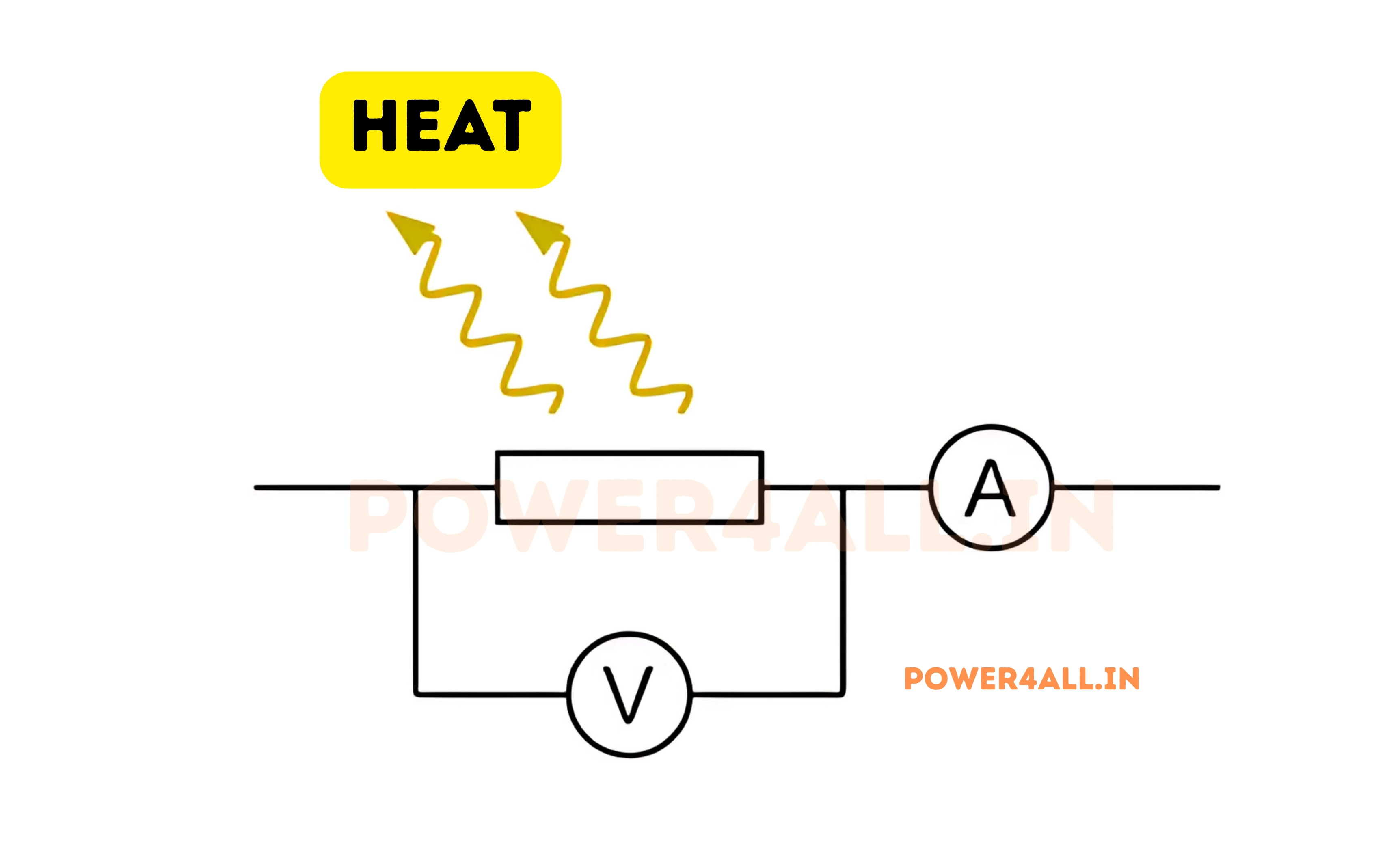
Heat Generation
Resistors convert electrical energy to heat energy, used in applications like electric heaters, toasters, and hair dryers.
Signal Conditioning
Resistors shape electrical signals, filter noise, and set operating points for amplifiers and other active components.
Resistor Symbol and Units
Circuit Symbols
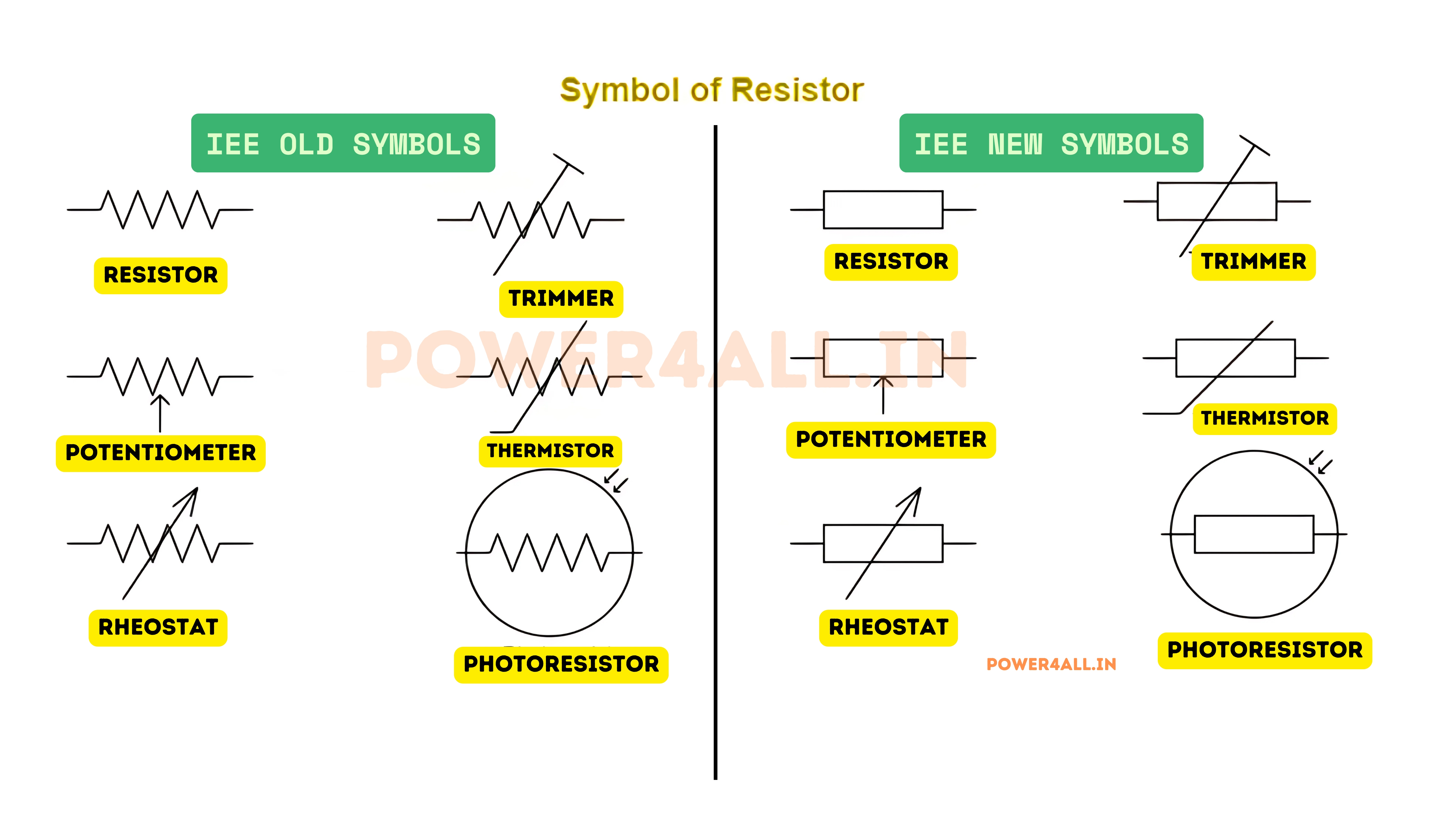
- American (ANSI): Zigzag line pattern
- International (IEC): Rectangle with connecting lines
- Variable resistor: Arrow through symbol
- Photoresistor: Symbol with light arrows
- Thermistor: Symbol with temperature notation
Units of Measurement
- Ohm (Ω): Basic unit of resistance
- Kiloohm (kΩ): 1,000 ohms
- Megohm (MΩ): 1,000,000 ohms
- Milliohm (mΩ): 0.001 ohms
- Named after: Georg Simon Ohm, German physicist
Everyday Resistor Examples
- LED current limiting: 220Ω resistor protects LED from burning out
- Volume control: Variable resistor (potentiometer) in audio equipment
- Heating element: Low-value, high-power resistor in electric heaters
- Pull-up resistor: 10kΩ resistor ensures digital signals stay high
- Temperature sensor: Thermistor changes resistance with temperature
- Light sensor: Photoresistor varies with light intensity
Did You Know?
The first resistors were made from carbon powder mixed with clay and baked into ceramic tubes. Modern resistors can be as small as a grain of sand (surface mount) or as large as a brick (high-power applications), with resistance values ranging from fractions of an ohm to billions of ohms!
Resistor Fundamentals: How They Work
Understanding how resistors actually work involves exploring the atomic-level interactions that create resistance, the materials used in construction, and the fundamental principles that govern their behavior in electrical circuits.
The Physics of Resistance
What Creates Electrical Resistance?
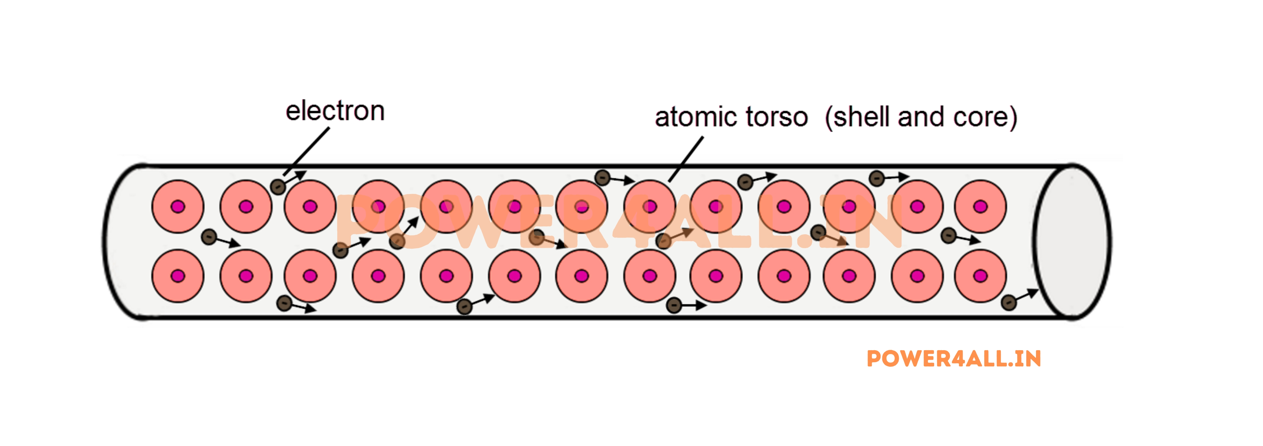
Resistance occurs when moving electrons collide with atoms in a material. These collisions convert some electrical energy into heat energy, which is why resistors get warm when current flows through them.
Microscopic View of Resistance
R = ρ × L / A
Resistance = Resistivity × Length / Cross-sectional Area
Factors Affecting Resistance
| Factor | Effect on Resistance | Why This Happens | Practical Example |
|---|---|---|---|
| Material Type | Different materials have vastly different resistance | Atomic structure affects electron mobility | Copper (low) vs Glass (very high) |
| Length | Longer = Higher resistance | More material = more collisions | 100ft vs 10ft wire |
| Cross-section | Thicker = Lower resistance | More paths for electron flow | Thick vs thin wire |
| Temperature | Usually higher temp = higher resistance | More atomic vibration = more collisions | Cold vs hot filament bulb |
Resistor Construction Materials
Carbon-Based Resistors
Most common and economical option
Carbon Composition
- Material: Carbon powder mixed with ceramic binder
- Construction: Molded into cylindrical shape
- Tolerance: ±5% to ±20% typical
- Advantages: Low cost, available in many values
- Disadvantages: Temperature sensitive, noisy
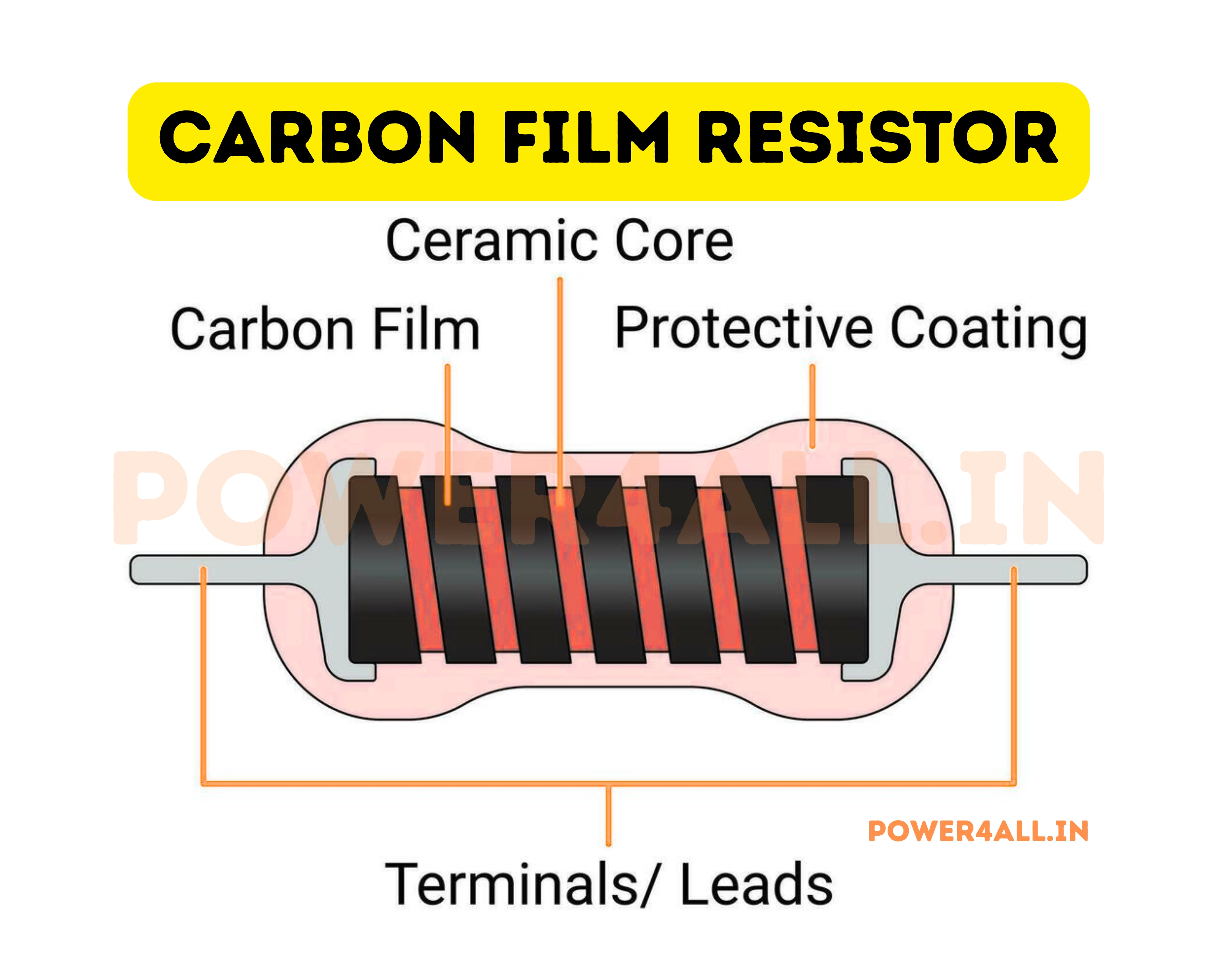
Carbon Film
- Material: Thin carbon film on ceramic core
- Tolerance: ±1% to ±5% typical
- Better performance: More stable than composition
- Applications: General purpose circuits
Metal-Based Resistors
Higher precision and stability
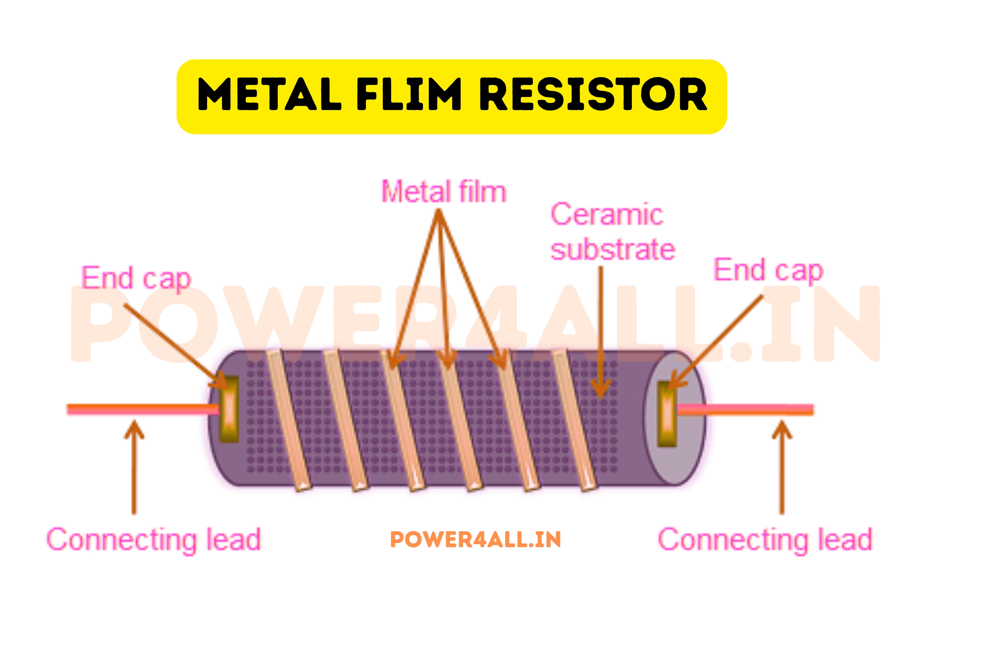
Metal Film
- Material: Thin metal alloy film (nichrome, tantalum)
- Tolerance: ±0.1% to ±1% achievable
- Temperature coefficient: Very low (stable)
- Noise level: Very low electrical noise
- Applications: Precision circuits, instrumentation
Metal Oxide
- Material: Metal oxide film on ceramic
- Power handling: Higher than metal film
- Temperature range: Excellent high-temp performance
- Applications: Power supplies, automotive
Wire Wound Resistors
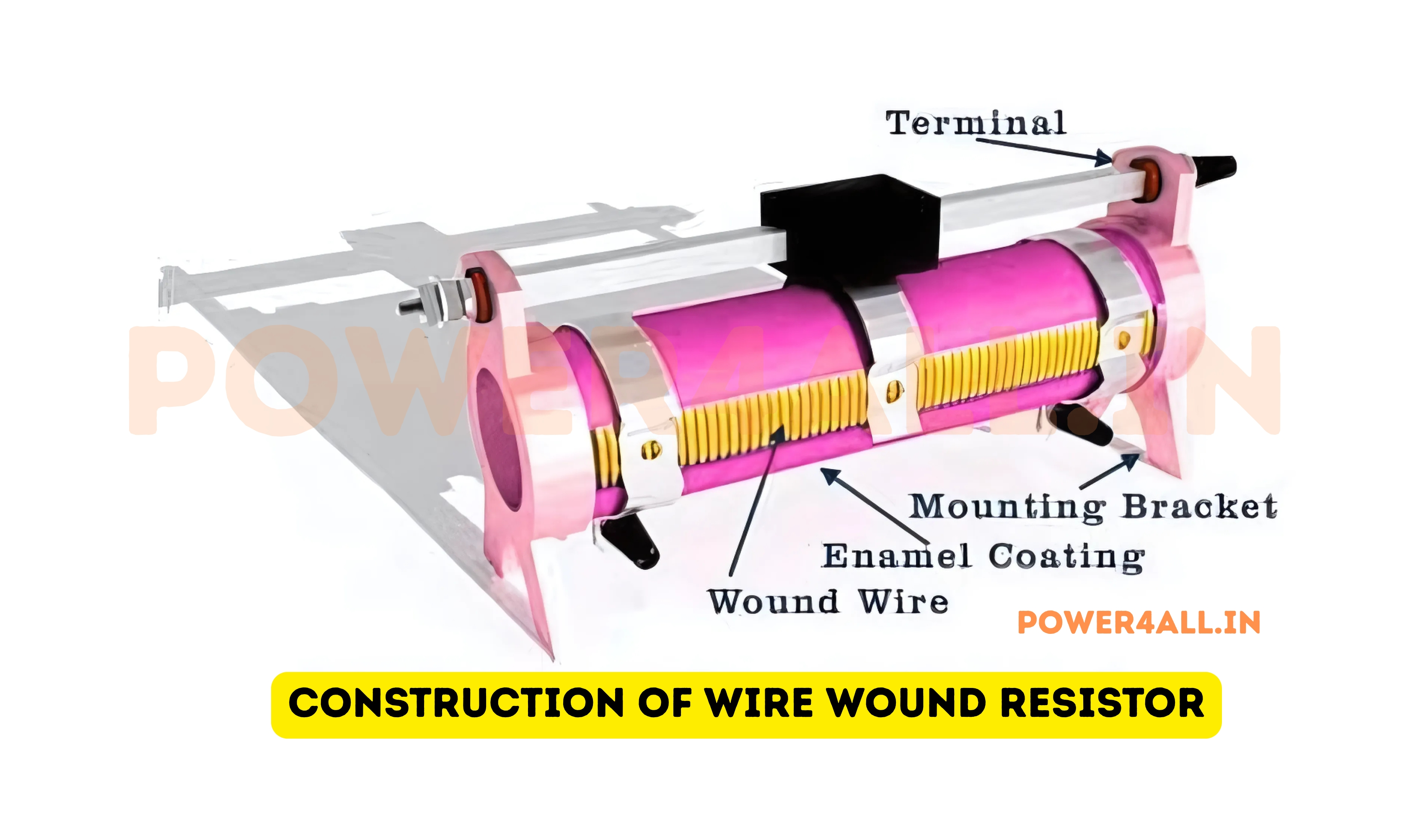
High power and precision applications
Construction Details
- Material: Resistance wire wound on ceramic core
- Wire types: Nichrome, constantan, manganin
- Power rating: 1W to thousands of watts
- Precision: ±0.01% achievable
- Limitation: Inductive at high frequencies
Specialty Types
- Precision wire wound: Laboratory standards
- Power wire wound: High wattage applications
- Non-inductive: Bifilar winding for RF use
- Adjustable: Variable tap positions
Temperature Effects on Resistance
How Temperature Changes Affect Resistor Performance
Temperature significantly affects resistor values. This effect is quantified by the Temperature Coefficient of Resistance (TCR), measured in parts per million per degree Celsius (ppm/°C).
R(T) = R₀ × [1 + α(T - T₀)]
Resistance at temperature T, where α is the temperature coefficient
| Resistor Type | Temperature Coefficient | Change per 100°C | Applications |
|---|---|---|---|
| Carbon composition | -800 to -1200 ppm/°C | -8% to -12% | Non-critical circuits |
| Carbon film | -200 to -800 ppm/°C | -2% to -8% | General purpose |
| Metal film | ±50 to ±200 ppm/°C | ±0.5% to ±2% | Precision circuits |
| Wire wound | ±20 to ±50 ppm/°C | ±0.2% to ±0.5% | High precision |
Temperature Effect Example
1kΩ metal film resistor (±100 ppm/°C) temperature change from 25°C to 125°C:
- Temperature change: ΔT = 125°C - 25°C = 100°C
- Resistance change: ΔR = 1000Ω × 100 ppm/°C × 100°C = 10Ω
- New resistance: R = 1000Ω + 10Ω = 1010Ω
- Percentage change: 1% increase
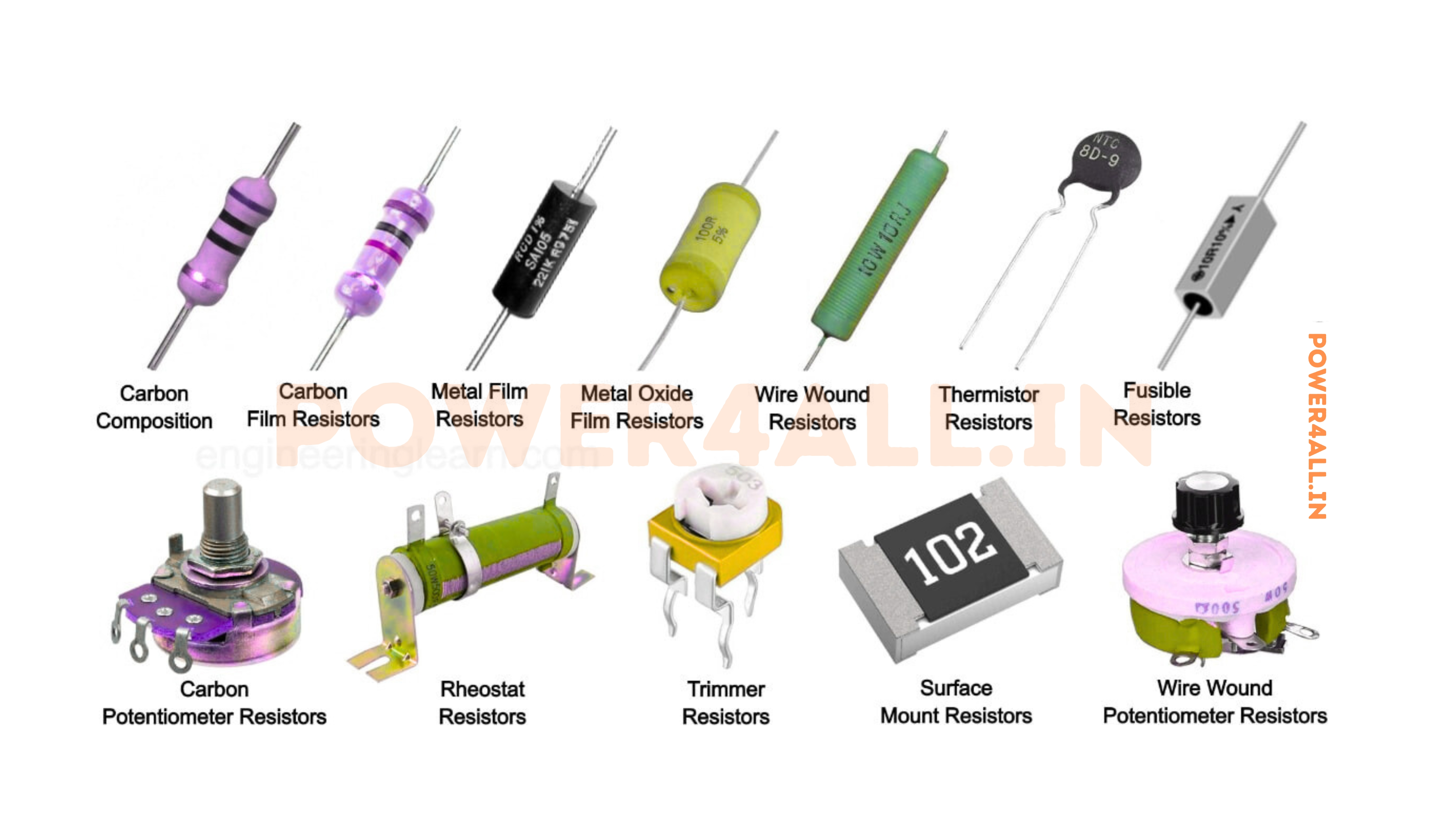
Types of Resistors: Complete Classification
Resistors come in many different types, each designed for specific applications and requirements. Understanding the various types helps in selecting the right resistor for your particular need, whether it's precision measurement, high power handling, or special environmental conditions.
Fixed Value Resistors
Through-Hole Resistors
Traditional resistors with leads for PCB mounting
Standard Sizes and Power Ratings
- 1/8 Watt (0.125W): 3-4mm body, general electronics
- 1/4 Watt (0.25W): 6mm body, most common size
- 1/2 Watt (0.5W): 8-9mm body, higher power needs
- 1 Watt: 11mm body, power supply circuits
- 2-5 Watts: Larger bodies, heat dissipation
Advantages
- Easy to handle and identify
- Color code clearly visible
- Good for prototyping
- Replaceable in circuits
- Lower cost than surface mount
Common Applications
- Hobby electronics and DIY projects
- Educational circuit boards
- Prototype development
- Repair and replacement work
- Low-volume production
Surface Mount Resistors (SMD)
Tiny resistors for modern electronics
Standard SMD Sizes
- 0201: 0.02" × 0.01" (0.6mm × 0.3mm)
- 0402: 0.04" × 0.02" (1.0mm × 0.5mm)
- 0603: 0.06" × 0.03" (1.6mm × 0.8mm)
- 0805: 0.08" × 0.05" (2.0mm × 1.25mm)
- 1206: 0.12" × 0.06" (3.2mm × 1.6mm)
Advantages
- Extremely compact size
- Lower parasitic inductance
- Automated assembly friendly
- Better high-frequency performance
- Cost effective in volume
Where You Find Them
- Smartphones and tablets
- Computer motherboards
- Automotive electronics
- IoT devices and sensors
- High-density circuit boards
Power Resistors
High wattage resistors for power applications
Power Ratings and Constructions
- 5-10 Watts: Ceramic housed, finned heat sinks
- 25-50 Watts: Aluminum housed, bolt mounting
- 100+ Watts: Liquid cooled, fan cooled options
- Kilowatt range: Grid resistors, load banks
Special Features
- Excellent heat dissipation
- Low temperature rise
- Robust construction
- High current capability
- Industrial mounting options
High Power Applications
- Motor start/brake resistors
- Load testing equipment
- Power supply bleeder resistors
- Heating elements
- Dynamic braking systems
Variable Resistors
Adjustable and Variable Resistance Components
Potentiometers (Pots)
Three-terminal variable resistors used for voltage division and user controls. The resistance between the center terminal and either end can be adjusted by turning a shaft or sliding a control.
Rotary Potentiometers
- Linear taper: Resistance changes proportionally
- Logarithmic taper: For audio volume controls
- Multi-turn: 10+ turns for precision adjustment
- Ganged: Multiple pots on one shaft
- Applications: Volume, tone, tuning controls
Slide Potentiometers
- Linear motion: Sliding control instead of rotary
- Visual feedback: Position easily seen
- Motorized versions: Computer controlled
- Precision types: Laboratory instruments
- Applications: Audio mixers, test equipment
Rheostats
Two-terminal variable resistors used to control current in a circuit. Unlike potentiometers, rheostats are connected in series with the load.
Rheostat Applications
- Light dimmers: Control incandescent bulb brightness
- Motor speed control: DC motor speed adjustment
- Heater control: Temperature adjustment
- Laboratory power supplies: Current limiting
Trimpots (Trimmer Potentiometers)
Small, preset variable resistors used for one-time or infrequent adjustments during manufacturing or servicing.
| Type | Adjustment Method | Typical Use | Adjustment Frequency |
|---|---|---|---|
| Cermet trimpot | Screwdriver adjustment | Circuit calibration | Set once during production |
| Carbon trimpot | Screwdriver or thumb wheel | Bias adjustment | Occasional service adjustment |
| Multi-turn trimpot | Precision screw drive | Precision calibration | Factory calibration only |
Special Purpose Resistors
Thermistors
Temperature-sensitive resistors
Types and Characteristics
- NTC (Negative Temperature Coefficient): Resistance decreases with temperature
- PTC (Positive Temperature Coefficient): Resistance increases with temperature
- Temperature range: -55°C to +200°C typical
- Sensitivity: Much higher than standard resistors
Thermistor Applications
- Temperature measurement and control
- Inrush current limiting (PTC)
- Temperature compensation circuits
- Digital thermometers
- Automotive temperature sensors
Photoresistors (LDR)
Light-dependent resistors
Operating Principles
- Light sensitivity: Resistance decreases with light intensity
- Material: Cadmium sulfide (CdS) most common
- Response time: Milliseconds to seconds
- Resistance range: MΩ in dark to kΩ in light
LDR Applications
- Automatic street lighting
- Camera light meters
- Security systems
- Display brightness control
- Solar tracking systems
Varistors (VDR)
Voltage-dependent resistors
Protection Characteristics
- Normal operation: Very high resistance
- Overvoltage condition: Resistance drops dramatically
- Clamping voltage: Limits voltage to safe levels
- Self-resetting: Returns to high resistance automatically
Varistor Applications
- Surge protection in power supplies
- Lightning protection systems
- Motor protection circuits
- Telecommunication equipment
- Automotive electronics protection
Resistor Color Code System: Reading Resistor Values
The resistor color code is a standardized system for indicating the resistance value and tolerance of through-hole resistors. Learning to read color codes is essential for working with electronics, as it allows you to quickly identify resistor values without needing measurement equipment.
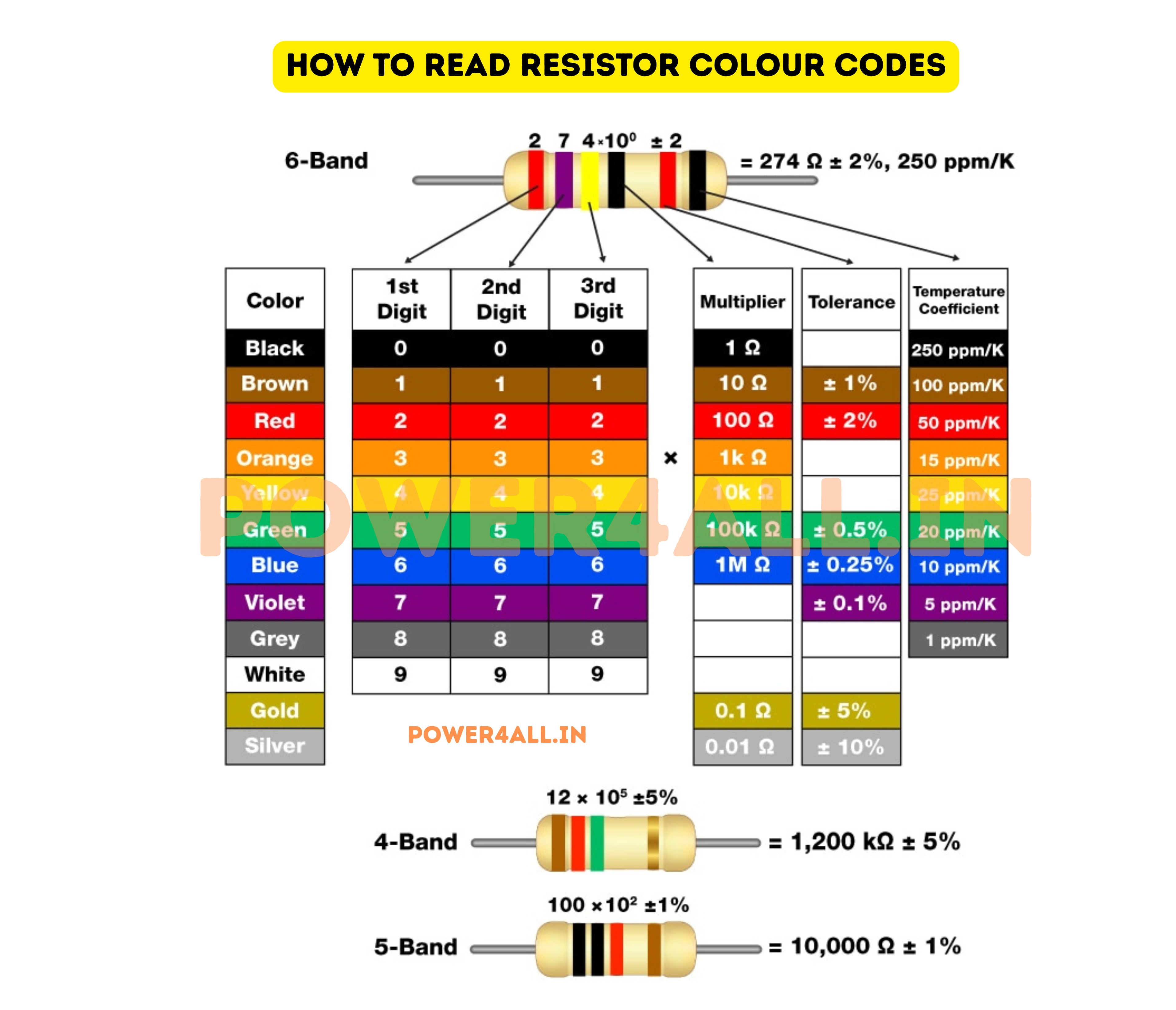
Standard Color Code Chart
| Color | Digit Value | Multiplier | Tolerance | Color Sample |
|---|---|---|---|---|
| Black | 0 | ×1 (10⁰) | - | Black |
| Brown | 1 | ×10 (10¹) | ±1% | Brown |
| Red | 2 | ×100 (10²) | ±2% | Red |
| Orange | 3 | ×1,000 (10³) | - | Orange |
| Yellow | 4 | ×10,000 (10⁴) | - | Yellow |
| Green | 5 | ×100,000 (10⁵) | ±0.5% | Green |
| Blue | 6 | ×1,000,000 (10⁶) | ±0.25% | Blue |
| Violet | 7 | ×10,000,000 (10⁷) | ±0.1% | Violet |
| Grey | 8 | ×100,000,000 (10⁸) | ±0.05% | Grey |
| White | 9 | ×1,000,000,000 (10⁹) | - | White |
| Gold | - | ×0.1 (10⁻¹) | ±5% | Gold |
| Silver | - | ×0.01 (10⁻²) | ±10% | Silver |
Reading Different Band Configurations
4-Band Resistors
Most common configuration (±5% or ±10% tolerance)
Band Order (left to right)
Example: 4-Band Reading
Colors: Red, Violet, Orange, Gold
- Red (1st): 2
- Violet (2nd): 7
- Orange (3rd): ×1,000
- Gold (4th): ±5%
- Result: 27 × 1,000 = 27,000Ω = 27kΩ ±5%
5-Band Resistors
Precision resistors (±1% or better tolerance)
Band Order (left to right)
Example: 5-Band Reading
Colors: Brown, Black, Orange, Red, Brown
- Brown (1st): 1
- Black (2nd): 0
- Orange (3rd): 3
- Red (4th): ×100
- Brown (5th): ±1%
- Result: 103 × 100 = 10,300Ω = 10.3kΩ ±1%
6-Band Resistors
High precision with temperature coefficient
Band Order (left to right)
| 6th Band Color | Temperature Coefficient | Application |
|---|---|---|
| Brown | 100 ppm/°C | General precision |
| Red | 50 ppm/°C | High precision |
| Orange | 15 ppm/°C | Ultra precision |
| Yellow | 25 ppm/°C | Precision instruments |
Memory Aids for Color Codes
Popular Mnemonics for Remembering Color Codes
Classic Mnemonics
For colors 0-9 (Black, Brown, Red, Orange, Yellow, Green, Blue, Violet, Grey, White):
- "Big Brown Rabbits Often Yield Great Big Vegetables Grown Wild"
- "Bad Boys Race Our Young Girls But Violet Generally Wins"
- "Black Brown Red Orange Yellow Green Blue Violet Grey White" (direct memorization)
Practical Reading Tips
Orientation
Tolerance band (usually gold or silver) goes on the right. If unsure, the tolerance band is typically separated from other bands.
Good Lighting
Read colors under good lighting. Some colors (brown/red, orange/yellow) can be difficult to distinguish in poor light.
Verification
Use a multimeter to verify readings, especially when learning or when colors are unclear or faded.
Apps Available
Smartphone apps can help identify resistor values using camera recognition, useful for beginners or difficult-to-read resistors.
Common Reading Mistakes
- Wrong orientation: Reading from right to left instead of left to right
- Color confusion: Mistaking brown for red, or orange for yellow
- Band counting: Missing or misidentifying the number of bands
- Multiplier confusion: Forgetting that multiplier adds zeros, doesn't multiply digits
- Tolerance ignorance: Not considering the tolerance range in calculations
Ohm's Law & Resistor Calculations
Ohm's Law is the fundamental relationship that governs how voltage, current, and resistance interact in electrical circuits. Understanding this law and its applications is essential for working with resistors and designing circuits that function safely and effectively.
The Fundamental Relationship
V = I × R
Voltage equals Current times Resistance
Derived Formulas
- Current: I = V / R
- Resistance: R = V / I
- Power: P = V × I = I²R = V²/R
Simple Example
9V battery connected to 1000Ω resistor:
- Current: I = V/R = 9V/1000Ω = 0.009A = 9mA
- Power: P = V²/R = 9²/1000 = 81/1000 = 0.081W = 81mW
- Safe operation: 81mW is well within a 1/4W resistor rating
Practical Calculation Examples
LED Current Limiting
Calculate resistor value to limit LED current
Result
Use a 470Ω, 1/4W resistor. This will give slightly more current (21.1mA) but within safe limits for most LEDs.
Voltage Divider Design
Create specific voltage from higher supply voltage
V_out = V_in × R2 / (R1 + R2)
Voltage divider formula
Power Dissipation Analysis
Ensure resistors can handle the power safely
Power Safety
Always derate power ratings by 50% or more for reliability. A 1/4W resistor should only handle about 0.125W in continuous operation.
Advanced Calculations
Complex Circuit Analysis with Multiple Resistors
Kirchhoff's Laws Application
For complex circuits with multiple resistors, we use Kirchhoff's Voltage Law (KVL) and Current Law (KCL) along with Ohm's Law.
Kirchhoff's Voltage Law (KVL)
Sum of voltage drops around any closed loop equals zero
ΣV = 0
Around any closed loop
Series Circuit Example
12V battery with 1kΩ and 2kΩ in series:
- Total resistance: 1kΩ + 2kΩ = 3kΩ
- Current: I = 12V/3kΩ = 4mA
- V across 1kΩ: 4mA × 1kΩ = 4V
- V across 2kΩ: 4mA × 2kΩ = 8V
- Check: 4V + 8V = 12V ✓
Kirchhoff's Current Law (KCL)
Current entering a node equals current leaving
ΣI_in = ΣI_out
At any node
Parallel Circuit Example
12V supply with 1kΩ and 2kΩ in parallel:
- Current through 1kΩ: I₁ = 12V/1kΩ = 12mA
- Current through 2kΩ: I₂ = 12V/2kΩ = 6mA
- Total current: I_total = 12mA + 6mA = 18mA
- Equivalent resistance: R_eq = 12V/18mA = 667Ω
- Check: 1/(1/1k + 1/2k) = 667Ω ✓
Temperature Effects on Calculations
Real-world resistor values change with temperature, affecting circuit calculations.
| Parameter | Cold (0°C) | Room Temp (25°C) | Hot (75°C) | Effect on Circuit |
|---|---|---|---|---|
| 1kΩ carbon resistor | 1020Ω | 1000Ω | 960Ω | ±4% current variation |
| 1kΩ metal film resistor | 1005Ω | 1000Ω | 995Ω | ±0.5% current variation |
| Current through resistor | 4.9mA | 5.0mA | 5.2mA | Proportional to resistance change |
Common Calculation Mistakes
Avoid These Common Errors
- Unit confusion: Mixing mA and A, kΩ and Ω in calculations
- Power miscalculation: Using wrong power formula for the given parameters
- Series/parallel confusion: Adding resistances incorrectly
- Tolerance ignorance: Not considering resistor tolerance in critical calculations
- Real-world factors: Ignoring temperature, aging, and tolerance effects
Power Ratings & Heat Management
Power rating is one of the most critical specifications for resistors, as it determines how much electrical power the resistor can safely dissipate as heat. Understanding power ratings, heat generation, and thermal management is essential for reliable circuit design and preventing component failure.
Understanding Power Dissipation
Why Resistors Generate Heat
When current flows through a resistor, electrical energy is converted to heat energy. This is not a byproduct or inefficiency - it's exactly how resistors work! The heat generation follows the fundamental power equations.
P = I²R = V²/R = V×I
Power dissipated as heat (in Watts)
Heat Generation Example
100Ω resistor with 1A current:
- Power: P = I²R = 1² × 100 = 100W
- Heat equivalent: Same as a 100W light bulb!
- Voltage drop: V = IR = 1A × 100Ω = 100V
- Temperature rise: Could exceed 500°C without cooling
- Conclusion: Needs proper heat sink and ventilation
Standard Power Ratings
| Power Rating | Physical Size | Typical Applications | Maximum Current* | Heat Considerations |
|---|---|---|---|---|
| 1/8 W (0.125W) | 3-4mm length | Low-power electronics, sensors | 11mA (1kΩ) | Minimal heating |
| 1/4 W (0.25W) | 6mm length | General electronics, indicators | 16mA (1kΩ) | Slight warming |
| 1/2 W (0.5W) | 8-9mm length | Power supplies, drivers | 22mA (1kΩ) | Noticeably warm |
| 1 W | 11mm length | Power circuits, current limiting | 32mA (1kΩ) | Hot to touch |
| 2-5 W | 15-20mm length | Power supplies, motor circuits | 45-71mA (1kΩ) | Requires heat sinking |
| 10+ W | Special packages | Power systems, heaters | 100+mA (1kΩ) | Active cooling needed |
*Maximum current values calculated for 1kΩ resistance using P = I²R at rated power
Derating and Safety Factors
Why You Should Never Use Full Power Rating
Using a resistor at its full power rating in continuous operation leads to high temperatures, shorter life, and potential failure. Proper engineering practice requires derating for reliability.
Recommended Derating Guidelines
50% Derating (Conservative)
Use only 50% of rated power for maximum reliability and long life. A 1W resistor should only dissipate 0.5W continuously.
70% Derating (Standard)
Industry standard for most applications. Provides good balance between component utilization and reliability.
Temperature Derating
Power rating decreases with ambient temperature. At 70°C ambient, most resistors can only handle 50% of their rated power.
Pulse vs Continuous
Resistors can handle higher power for short pulses. Continuous operation requires more conservative ratings.
| Application Type | Recommended Derating | Reason | Example |
|---|---|---|---|
| Critical systems | 50% or less | Maximum reliability required | Medical devices, aerospace |
| Commercial products | 60-70% | Balance cost vs reliability | Consumer electronics |
| High temperature environment | 40-50% | Reduced heat dissipation | Automotive under-hood |
| Pulse applications | 80-90% | Thermal mass absorbs heat | Switch-mode power supplies |
Derating Calculation Example
Need to dissipate 0.75W continuously in a 50°C environment:
- 50% derating: Need 0.75W ÷ 0.5 = 1.5W rated resistor
- Temperature derating: At 50°C, further reduce by 20%
- Final requirement: 1.5W ÷ 0.8 = 1.875W
- Selection: Choose 2W or 3W rated resistor
Heat Dissipation and Thermal Management
Natural Air Cooling
Simplest cooling method for low to medium power
Key Factors
- Surface area: Larger resistors dissipate heat better
- Orientation: Vertical mounting improves convection
- Spacing: Allow air circulation around components
- Enclosure ventilation: Provide air inlet/outlet
Natural Cooling Guidelines
- Space resistors at least 5mm apart
- Mount power resistors vertically when possible
- Keep hot components away from sensitive ICs
- Use larger PCB copper areas for heat spreading
Heat Sinks and Forced Air
Enhanced cooling for higher power applications
Heat Sink Types
- Aluminum extrusions: Cost-effective, good performance
- Finned heat sinks: Maximum surface area
- Thermal interface materials: Improve heat transfer
- Mounting hardware: Proper mechanical and thermal contact
R_thermal = ΔT / P
Thermal resistance = Temperature rise / Power
Liquid Cooling
Ultimate cooling for very high power applications
Applications
- Load testing: Kilowatt-level resistive loads
- Industrial systems: High-power motor controls
- Research equipment: Precision high-power circuits
- Grid applications: Utility-scale resistive loads
When to Use Liquid Cooling
Consider liquid cooling for continuous power dissipation above 50W per resistor, or when ambient temperatures exceed 40°C.
Temperature Rise and Safety
Safety Warning
Resistors operating at high power can reach temperatures exceeding 200°C (392°F). This can cause burns, ignite flammable materials, or damage nearby components. Always consider fire safety and component spacing in high-power designs.
Temperature Rise Estimation
Typical thermal resistance values for air-cooled resistors:
- 1/4W resistor: 300°C/W → 0.25W × 300 = 75°C rise
- 1W resistor: 100°C/W → 1W × 100 = 100°C rise
- 5W resistor: 50°C/W → 5W × 50 = 250°C rise
- With heat sink: Can reduce thermal resistance by 10× or more
Series & Parallel Resistor Combinations
Understanding how resistors behave when connected in series and parallel is fundamental to circuit design. These combinations allow you to create precise resistance values, divide voltages, control currents, and increase power handling capability beyond what single resistors can provide.
Series Resistor Combinations
Series Connection Rules
In series connections, resistors are connected end-to-end in a single path. Current must flow through each resistor in sequence.
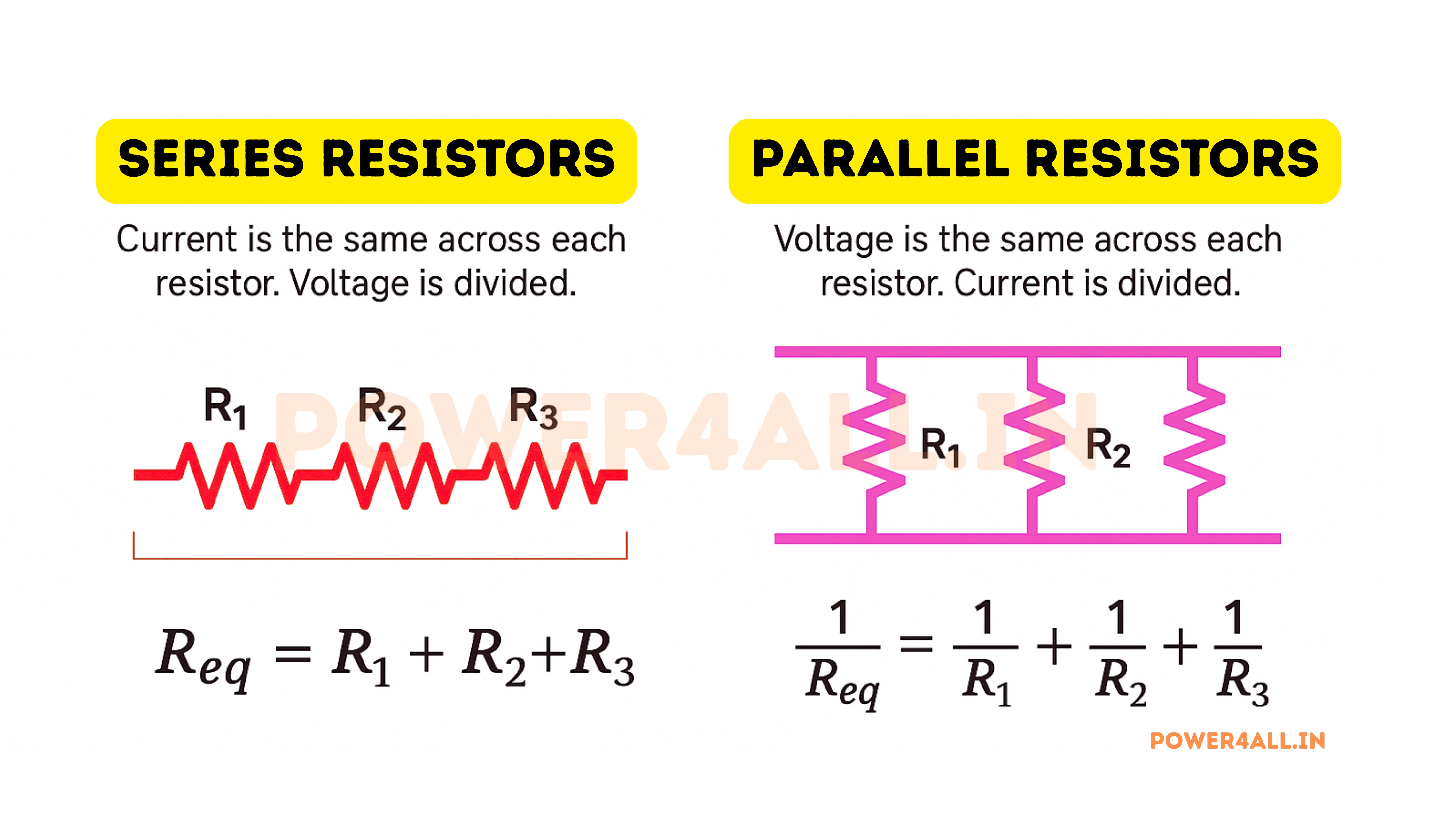
R_total = R1 + R2 + R3 + ...
Total resistance equals sum of individual resistances
Key Characteristics
- Same current: Identical current through all resistors
- Voltage divides: Voltage splits proportionally
- Power adds: Total power = sum of individual powers
- Higher total resistance: Always greater than largest individual resistor
Series Example
Three resistors: 100Ω, 220Ω, 330Ω in series with 12V:
- Total resistance: 100 + 220 + 330 = 650Ω
- Circuit current: I = 12V ÷ 650Ω = 18.5mA
- Voltage across 100Ω: 18.5mA × 100Ω = 1.85V
- Voltage across 220Ω: 18.5mA × 220Ω = 4.07V
- Voltage across 330Ω: 18.5mA × 330Ω = 6.08V
- Check: 1.85 + 4.07 + 6.08 = 12V ✓
Practical Series Applications
Voltage Dividers
Create specific voltages from higher supply voltage
V_out = V_in × R2/(R1+R2)
Output voltage from voltage divider
3.3V from 5V Supply
- Ratio needed: 3.3V/5V = 0.66
- Choose R1 = 1.7kΩ, R2 = 3.3kΩ
- Check: 5V × 3.3k/(1.7k+3.3k) = 3.3V ✓
- Current: 5V/5kΩ = 1mA (low power)
Current Limiting
Control current to sensitive components
LED Current Limiting Chain
3 LEDs in series with current limiting resistor:
- Supply voltage: 12V
- LED voltage drop: 3 × 2.1V = 6.3V
- Resistor voltage: 12V - 6.3V = 5.7V
- Desired current: 20mA
- Required resistor: 5.7V ÷ 20mA = 285Ω
- Use standard: 270Ω or 300Ω
High Voltage Applications
Distribute voltage stress across multiple resistors
High Voltage Divider
1000V measurement with 10:1 divider:
- R1 (high side): 9MΩ (900V across it)
- R2 (low side): 1MΩ (100V across it)
- Output: 100V for 1000V input
- Safety: Each resistor sees only portion of total voltage
Parallel Resistor Combinations
Parallel Connection Rules
In parallel connections, resistors are connected side-by-side with common connection points. Each resistor provides an alternate path for current.
1/R_total = 1/R1 + 1/R2 + 1/R3 + ...
Reciprocal formula for parallel resistance
Key Characteristics
- Same voltage: Identical voltage across all resistors
- Current divides: Current splits based on resistance
- Power adds: Total power = sum of individual powers
- Lower total resistance: Always less than smallest individual resistor
Parallel Example
Three resistors: 100Ω, 200Ω, 300Ω in parallel with 12V:
- 1/R_total = 1/100 + 1/200 + 1/300
- 1/R_total = 0.01 + 0.005 + 0.0033 = 0.0183
- R_total = 1/0.0183 = 54.6Ω
- Current through 100Ω: 12V ÷ 100Ω = 120mA
- Current through 200Ω: 12V ÷ 200Ω = 60mA
- Current through 300Ω: 12V ÷ 300Ω = 40mA
- Total current: 120 + 60 + 40 = 220mA
Practical Parallel Applications
When and Why to Use Parallel Resistors
Creating Non-Standard Values
Need 75Ω but only have 150Ω resistors
- Two 150Ω in parallel: R = 150Ω ÷ 2 = 75Ω ✓
- General rule: N identical resistors in parallel = R ÷ N
- Power benefit: Each resistor handles half the current
- Cost benefit: Use common values instead of special orders
Increasing Power Handling
| Configuration | Resistance | Power Rating | Current Capability | Use Case |
|---|---|---|---|---|
| Single 10Ω, 1W | 10Ω | 1W | 316mA | Basic application |
| Two 20Ω, 1W in parallel | 10Ω | 2W | 447mA | Higher power needed |
| Four 40Ω, 1W in parallel | 10Ω | 4W | 632mA | High current application |
Current Sharing and Load Distribution
Equal Current Sharing
Identical resistors in parallel share current equally, preventing any single resistor from being overloaded.
Redundancy
If one resistor fails open, others continue to carry current. Critical for safety applications.
Heat Distribution
Heat generation is spread across multiple components, improving thermal management.
Cost Optimization
Multiple low-power resistors often cost less than one high-power resistor.
Complex Combinations
Series-Parallel Networks and Advanced Calculations
Step-by-Step Analysis Method
Complex Network Example
Network: R1(100Ω) in series with [R2(200Ω) parallel with R3(300Ω)]
- Step 1: Calculate R2||R3 = (200×300)/(200+300) = 120Ω
- Step 2: Total = R1 + R2||R3 = 100Ω + 120Ω = 220Ω
- With 12V applied: Total current = 12V/220Ω = 54.5mA
- Voltage across R1: 54.5mA × 100Ω = 5.45V
- Voltage across parallel pair: 12V - 5.45V = 6.55V
- Current through R2: 6.55V/200Ω = 32.8mA
- Current through R3: 6.55V/300Ω = 21.8mA
Quick Parallel Formulas
| Configuration | Formula | Quick Calculation | Example |
|---|---|---|---|
| Two resistors | R = (R1×R2)/(R1+R2) | Product over sum | (100×200)/(100+200) = 66.7Ω |
| Equal resistors | R = R_value/N | Value divided by quantity | 4×100Ω = 100Ω/4 = 25Ω |
| One much smaller | R ≈ R_smallest | Dominated by smallest | 1Ω||1MΩ ≈ 1Ω |
Practical Applications: Resistors in Real Circuits
Resistors are found in virtually every electronic device, performing essential functions from simple current limiting to complex signal processing. Understanding their practical applications helps bridge the gap between theory and real-world circuit design.
Basic Circuit Functions
LED Current Limiting
Protecting LEDs from overcurrent damage
Why LEDs Need Current Limiting
- Exponential I-V curve: Small voltage changes cause large current changes
- No internal resistance: LEDs have virtually no current limiting
- Temperature sensitive: LED resistance decreases as they heat up
- Destructive failure: Overcurrent permanently damages LED junction
LED Resistor Calculation
Red LED: Forward voltage = 1.8V, Desired current = 15mA, Supply = 5V
- Resistor voltage: 5V - 1.8V = 3.2V
- Resistor value: R = 3.2V ÷ 0.015A = 213Ω
- Standard value: Use 220Ω (closest standard)
- Actual current: 3.2V ÷ 220Ω = 14.5mA (acceptable)
- Power rating: P = I²R = (0.0145)² × 220 = 46mW
- Resistor choice: 1/8W resistor is adequate
Pull-up and Pull-down Resistors
Ensuring digital signals have defined logic levels
Pull-up Resistors
- Function: Pull signal to logic HIGH when not driven
- Typical values: 1kΩ to 100kΩ
- Applications: Reset buttons, I2C bus, open-drain outputs
- Connection: Between signal line and VCC
Pull-down Resistors
- Function: Pull signal to logic LOW when not driven
- Typical values: 1kΩ to 100kΩ
- Applications: Switch inputs, enable pins
- Connection: Between signal line and ground
Pull-up Resistor Value Selection
Factors to consider:
- Too low (1kΩ): High power consumption when pulled low
- Too high (1MΩ): Slow switching, noise susceptible
- Typical choice (10kΩ): Good balance for most applications
- I2C bus (4.7kΩ): Standard value for I2C communication
Voltage Dividers for Sensing
Converting sensors to usable voltage ranges
Common Sensor Applications
- Potentiometer position: Variable voltage output
- Thermistor temperature: Temperature to voltage conversion
- Photoresistor light: Light intensity to voltage
- Battery monitoring: Scale down battery voltage
Temperature Sensor Circuit
10kΩ NTC thermistor with 10kΩ fixed resistor:
- At 25°C: Thermistor = 10kΩ, Output = 2.5V
- At 0°C: Thermistor = 32kΩ, Output = 1.2V
- At 50°C: Thermistor = 3.6kΩ, Output = 3.7V
- ADC input: 0-5V range covers wide temperature span
Advanced Circuit Applications
Sophisticated Uses in Modern Electronics
Operational Amplifier Circuits
Op-Amp Gain Setting
Precision resistors determine amplifier gain
Gain = 1 + (Rf / Rin)
Non-inverting amplifier gain formula
Precision Gain Example
Need exact 10× gain for sensor amplifier:
- Required: Gain = 10, so Rf/Rin = 9
- Choose Rin = 10kΩ, Rf = 90kΩ
- Tolerance effect: ±1% resistors give ±2% gain accuracy
- Temperature drift: Matched resistors cancel temperature effects
Active Filters
RC networks create frequency-selective circuits
fc = 1 / (2π × R × C)
Cutoff frequency for RC filter
Audio Filter Design
Low-pass filter for 1kHz cutoff:
- Choose C = 100nF (common value)
- Calculate R = 1/(2π×1000×100×10⁻⁹) = 1.59kΩ
- Use standard 1.6kΩ resistor
- Actual fc = 995Hz (close enough)
Digital Circuit Applications
| Application | Typical Value | Purpose | Critical Parameters |
|---|---|---|---|
| Current limiting for GPIOs | 220Ω - 1kΩ | Protect microcontroller pins | Maximum current rating |
| Crystal oscillator feedback | 1MΩ - 10MΩ | Bias crystal in linear region | Low leakage, stability |
| UART/SPI termination | 120Ω | Match transmission line impedance | Precision tolerance |
| Reset circuits | 10kΩ pull-up | Ensure defined reset state | Power consumption vs speed |
| LED indicators | 220Ω - 470Ω | Limit LED current | Power rating for continuous use |
Power Supply and Protection Circuits
Bleeder Resistors
High-value resistors across filter capacitors safely discharge stored energy when power is removed, preventing electric shock hazards.
Current Sensing
Low-value, precision shunt resistors (milliohms) measure current by monitoring voltage drop using Ohm's Law.
Thermal Compensation
Temperature-matched resistor networks compensate for thermal drift in precision circuits like voltage references.
Surge Limiting
High-power resistors limit inrush current during power-up, protecting sensitive components from startup surges.
Industry-Specific Applications
Specialized Uses Across Different Industries
Automotive Electronics
- Engine control units: Sensor conditioning, actuator control
- Safety systems: ABS, airbag deployment timing
- Comfort features: Climate control, seat heating
- Infotainment: Audio processing, display backlighting
- Charging systems: Current monitoring, protection
Automotive Requirements
Must withstand -40°C to +125°C, vibration, moisture, and electrical transients. AEC-Q200 qualified components preferred.
Medical Devices
- Patient monitoring: ECG, blood pressure, temperature sensors
- Imaging equipment: X-ray, MRI, ultrasound signal processing
- Therapeutic devices: Pacemakers, defibrillators, stimulators
- Diagnostic tools: Blood analyzers, glucose meters
- Safety isolation: Patient protection from electrical hazards
Medical Requirements
Ultra-high reliability, biocompatibility, regulatory compliance (FDA, CE marking), and fail-safe operation are mandatory.
Telecommunications
- Signal conditioning: Line drivers, receivers, equalizers
- Impedance matching: 50Ω, 75Ω transmission lines
- Power distribution: DC-DC converters, current sharing
- Protection circuits: Surge, overvoltage, ESD protection
- Filtering: EMI suppression, signal bandwidth limiting
Telecom Precision Example
75Ω coaxial cable termination:
- Requires exactly 75Ω ±1% for minimum reflections
- Temperature coefficient <100ppm/°C for stability
- Low noise for signal integrity
- High frequency performance to GHz range
Resistor Selection Guide: Choosing the Right Component
Selecting the right resistor for your application involves considering multiple factors beyond just resistance value. This comprehensive guide will help you make informed decisions based on your specific requirements, ensuring optimal performance and reliability.
Selection Criteria Matrix
| Application Type | Recommended Type | Tolerance | Power Rating | Special Requirements | Cost Impact |
|---|---|---|---|---|---|
| General purpose hobby | Carbon film, 1/4W | ±5% | 50% derating | None | Lowest cost |
| Digital circuits | Metal film or thick film | ±1% to ±5% | Low power typically | Low noise, fast response | Low to medium |
| Precision analog | Metal film, thin film | ±0.1% to ±1% | Conservative derating | Low TCR, matched pairs | Medium to high |
| RF/High frequency | Thin film, chip resistors | ±1% to ±5% | Based on power | Low inductance/capacitance | Medium to high |
| High power | Wire wound, metal oxide | ±1% to ±5% | Significant derating | Heat sinking, cooling | High |
| Automotive/Industrial | Metal film, thick film | ±1% to ±5% | Wide temp derating | AEC-Q200, wide temp range | Medium to high |
Step-by-Step Selection Process
Detailed Selection Factors
Tolerance Requirements
How accurate does your resistor need to be?
Tolerance Impact on Circuit Performance
- ±20% (Silver): Very old or low-cost applications
- ±10% (Silver): Non-critical applications, LEDs
- ±5% (Gold): General purpose, most common choice
- ±1% (Brown): Better accuracy for filters, dividers
- ±0.5% (Green): Precision measurement circuits
- ±0.1% (Violet): High-precision instrumentation
Tolerance Selection Example
Voltage divider for 3.3V from 5V (66% ratio):
- ±5% resistors: Output range 3.0V to 3.6V
- ±1% resistors: Output range 3.2V to 3.4V
- For 3.3V ±5% spec: Need ±1% resistors minimum
- Cost impact: ±1% costs ~50% more than ±5%
Temperature Considerations
How will temperature affect your circuit?
Temperature Coefficient (TCR) Impact
| Resistor Type | TCR (ppm/°C) | 100°C Change Effect |
|---|---|---|
| Carbon composition | -800 to -1200 | -8% to -12% |
| Carbon film | -200 to -800 | -2% to -8% |
| Metal film | ±50 to ±200 | ±0.5% to ±2% |
| Precision metal film | ±25 to ±50 | ±0.25% to ±0.5% |
Temperature Design Rule
For precision circuits operating over wide temperature ranges, temperature coefficient often matters more than initial tolerance. Choose TCR specification carefully.
Frequency Response
High-frequency behavior and parasitic effects
Parasitic Elements
- Parasitic inductance: Wire wound resistors have highest
- Parasitic capacitance: Limits high-frequency performance
- Skin effect: Reduces effective resistance at high frequencies
- Thermal noise: Johnson noise increases with resistance and temperature
f_corner = 1/(2π√LC)
Self-resonant frequency from parasitic L and C
High-Frequency Guidelines
- DC to 1MHz: Standard resistors work fine
- 1-100MHz: Use film resistors, avoid wire wound
- 100MHz-1GHz: Thin film chip resistors preferred
- >1GHz: Specialized RF resistors required
Standard Values and E-Series
Understanding Standard Resistor Values
Resistors are manufactured in standard values based on E-series (derived from Renard series). This system ensures adequate value coverage while minimizing the number of different values needed.
Common E-Series Values
| Series | Tolerance | Values per Decade | Example Values (1-10 range) |
|---|---|---|---|
| E6 | ±20% | 6 | 1.0, 1.5, 2.2, 3.3, 4.7, 6.8 |
| E12 | ±10% | 12 | 1.0, 1.2, 1.5, 1.8, 2.2, 2.7, 3.3, 3.9, 4.7, 5.6, 6.8, 8.2 |
| E24 | ±5% | 24 | 1.0, 1.1, 1.2, 1.3, 1.5, 1.6, 1.8, 2.0, 2.2, 2.4, 2.7, 3.0... |
| E48 | ±2% | 48 | More intermediate values available |
| E96 | ±1% | 96 | Very fine resolution for precision applications |
Finding Closest Standard Values
Selection Strategy
Need 1347Ω resistor for LED current limiting:
- E24 series closest: 1300Ω (3.5% low) or 1500Ω (11.4% high)
- Choose 1300Ω: Slightly higher LED current, usually acceptable
- Or choose 1500Ω: Lower LED current, safer for LED
- Check current: Verify actual current is within LED specifications
Series/Parallel Combinations for Exact Values
Series Combination
Add standard values to get exact resistance. Example: 1347Ω = 1000Ω + 330Ω + 18Ω (using E24 values).
Parallel Combination
Use parallel formula for values between standards. Example: 750Ω = 1500Ω || 1500Ω.
Online Calculators
Many online tools can find optimal combinations of standard values to achieve target resistance.
Cost Consideration
Single precision resistor often costs less than multiple standard values, especially in production.
Cost Optimization Strategies
Smart Cost Management
- Standardize on common values: E12 or E24 series for volume discounts
- Choose appropriate tolerance: Don't over-specify precision unnecessarily
- Consider package type: SMD often cheaper in volume than through-hole
- Plan for second sources: Ensure multiple suppliers for critical values
- Volume breaks: Significant price reduction at 1K, 10K, 100K quantities
- Obsolescence planning: Choose mainstream parts with long-term availability
Testing & Troubleshooting Resistors
Testing resistors properly and troubleshooting resistor-related problems are essential skills for anyone working with electronics. This section covers measurement techniques, common failure modes, and systematic troubleshooting approaches.
Basic Resistance Measurement
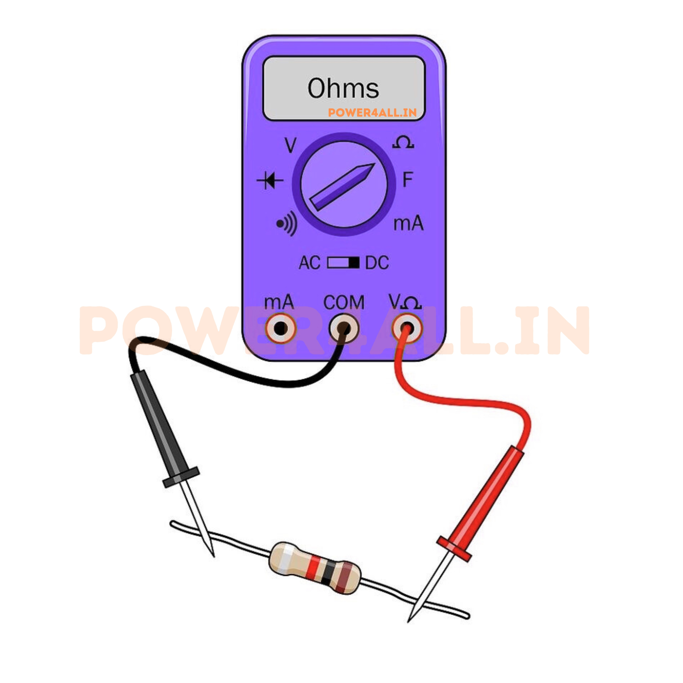
Using a Digital Multimeter
The most common tool for resistor testing
Proper Measurement Technique
Common Measurement Errors
- Parallel paths: Other circuit components affect reading
- Body resistance: Holding both probe tips affects high-value resistors
- Poor contact: Oxidized leads or dirty probes give false readings
- Wrong range: Auto-ranging may be slow or inaccurate
In-Circuit Testing Challenges
Testing resistors without removing them from circuits
Why In-Circuit Testing is Difficult
- Parallel paths: Other components provide alternate current paths
- Active components: Transistors, diodes, ICs affect measurements
- Power rails: Even small voltages can cause errors
- Coupling effects: Capacitors, inductors modify AC test signals
In-Circuit Testing Strategies
Practical Approaches
- Lift one end: Desolder one lead to isolate resistor
- Compare to schematic: Know what resistance to expect
- Use ESR meters: Specialized meters for in-circuit testing
- Functional testing: Verify circuit operation rather than component values
Precision Measurement Techniques
High-accuracy measurements for critical applications
4-Wire (Kelvin) Measurement
Eliminates lead resistance errors by using separate current-carrying and voltage-sensing leads.
R = V_sense / I_force
True resistance using 4-wire method
When to Use Precision Methods
- Low resistance: <1Ω measurements need 4-wire technique
- High accuracy: Better than 0.1% measurements
- Current shunts: Milliohm resistance measurements
- Calibration work: Standards and reference resistors
Common Resistor Failure Modes
How Resistors Fail and Why
Types of Resistor Failures
| Failure Mode | Symptoms | Common Causes | Detection Method | Prevention |
|---|---|---|---|---|
| Open Circuit | Infinite resistance, no current flow | Overcurrent, overheating, mechanical stress | DMM shows OL (overload) | Proper power derating, strain relief |
| Value Drift | Resistance changes over time | Temperature cycling, aging, moisture | Compare to color code or specs | Quality components, controlled environment |
| Thermal Damage | Discoloration, cracking, value change | Excessive power dissipation | Visual inspection, resistance check | Adequate power rating, cooling |
| Physical Damage | Cracks, broken leads, internal breaks | Mechanical stress, vibration, impact | Visual inspection, continuity test | Proper mounting, vibration damping |
| Environmental | Corrosion, contamination effects | Humidity, chemicals, salt spray | Visual inspection, performance test | Conformal coating, sealed packages |
Visual Inspection Guidelines
Color Changes
Brown, black, or dark discoloration indicates overheating. Light color changes may indicate aging or contamination.
Physical Cracks
Hairline cracks in resistor body or coating can indicate thermal stress or mechanical damage.
Lead Corrosion
Green or white deposits on leads indicate corrosion from moisture or chemical exposure.
Heat Damage Signs
Burned PCB traces, discolored nearby components, or melted plastic indicates severe overheating.
Systematic Troubleshooting Approach
Circuit-Level Troubleshooting
Component-Level Analysis
LED Circuit Troubleshooting
Problem: LED not lighting
- Check power: Is voltage present at LED circuit?
- Test LED: Use DMM diode test function
- Check current limiting resistor: Measure resistance value
- Verify connections: Look for broken traces or bad solder
- Calculate expected current: Compare to actual measurement
Advanced Testing Equipment
Professional Test Equipment for Resistors
Specialized Test Instruments
LCR Meters
Measure inductance, capacitance, and resistance
- AC test signals: Multiple frequencies available
- Parasitic measurement: See L and C components
- High accuracy: 0.1% or better capability
- Temperature testing: Some models include temperature chambers
Thermal Testing
Measure temperature coefficient and thermal behavior
- Temperature chambers: Controlled temperature environments
- Thermal cameras: Hot spot identification
- TCR measurement: Precise temperature coefficient determination
- Power cycling: Test thermal stress effects
Noise Testing
Measure electrical noise characteristics
- Current noise: Excess noise beyond thermal noise
- 1/f noise: Low-frequency noise characteristics
- Voltage coefficient: Resistance change with applied voltage
- Audio applications: Critical for high-end audio circuits
Automated Test Equipment (ATE)
Production Testing Capabilities
- High-speed measurement: Thousands of components per hour
- Statistical analysis: Track parameter distributions
- Binning: Sort components by performance grades
- Traceability: Database recording of all measurements
- Standards compliance: Automatic verification against specifications
Troubleshooting Decision Tree
Quick Troubleshooting Guide
Safety Considerations When Working with Resistors
While resistors are generally safe components, proper handling and circuit design practices are essential to prevent injury, component damage, and fire hazards, especially when working with high-power applications or sensitive electronic systems.
Important Safety Warning
HIGH TEMPERATURE HAZARD: Power resistors can reach temperatures exceeding 200°C (392°F) during normal operation. Always allow adequate cooling time before handling, and use appropriate protection when working near hot components.
Power Resistor Safety
Thermal Hazards
High-power resistors generate significant heat
Temperature Safety Guidelines
- Surface temperatures: Can exceed 200°C on high-power resistors
- Burn hazard: Instant burns possible from contact with hot surfaces
- Fire risk: Nearby flammable materials can ignite
- Component damage: Heat can damage adjacent components
Safety Precautions
- Allow 15+ minutes cooling time after power-off
- Use heat-resistant gloves when necessary
- Maintain safe clearances from flammable materials
- Install thermal protection and monitoring systems
- Use proper ventilation and heat sinks
Electrical Safety
High voltages and currents in power circuits
Electrical Hazards
- High voltage: Dangerous voltages across resistors in HV circuits
- High current: Severe burns from high-current paths
- Stored energy: Energy storage in associated reactive components
- Arc flash: Potential for electrical arcing in high-power circuits
Electrical Safety Measures
- Always de-energize circuits before working
- Use lockout/tagout procedures
- Verify zero energy state with meters
- Use appropriate PPE for voltage levels
- Follow arc flash safety protocols
Fire Prevention
Preventing fires from resistor overheating
Fire Risk Factors
- Overload conditions: Excessive current causing overheating
- Component failure: Short circuits or partial failures
- Poor ventilation: Inadequate heat dissipation
- Flammable materials: Paper, plastic, or wood near hot resistors
Fire Prevention Strategies
- Install thermal fuses and protection circuits
- Use flame-retardant materials in enclosures
- Maintain proper clearances and ventilation
- Regular inspection of high-power circuits
- Install smoke detection systems
General Safety Best Practices
- Always derate components: Use conservative power ratings
- Provide adequate cooling: Heat sinks, fans, ventilation
- Use protection circuits: Fuses, circuit breakers, thermal protection
- Regular maintenance: Inspect for signs of overheating or damage
- Proper training: Ensure all personnel understand safety procedures
- Emergency procedures: Know how to safely shut down and evacuate
Frequently Asked Questions about Resistors
Common questions and expert answers about resistors, their applications, and troubleshooting. These FAQs address both beginner and advanced topics to help you understand and work with resistors effectively.
Basic Resistor Questions
Q: What exactly does a resistor do in a circuit?
A: A resistor controls the flow of electric current by providing resistance. Think of it like a valve in a water pipe - it restricts flow and creates a voltage drop. This allows resistors to limit current to safe levels, divide voltages, and convert electrical energy to heat when needed.
Q: Why do resistors have color bands instead of printed numbers?
A: Color bands are used because they're visible from any angle, don't wear off easily, work in all lighting conditions, and can be read even when the resistor is mounted on a circuit board. Numbers might be too small to read on tiny resistors or could be oriented away from view.
Q: Can I use a higher wattage resistor than required?
A: Yes, absolutely! Using a higher wattage resistor is always safe and often recommended. A 1W resistor can handle any load that a 1/4W resistor can, plus much more. The only downsides are slightly larger size and higher cost.
Q: What happens if I use the wrong resistor value?
A: It depends on the application. In an LED circuit, wrong resistance might make the LED too dim, too bright, or damaged. In a digital circuit, it might affect switching speed or noise immunity. Always calculate the correct value using Ohm's Law for your specific application.
Practical Application Questions
Q: How do I choose between 1% and 5% tolerance resistors?
A: Use 1% resistors when circuit performance depends on precise resistance values (like precision voltage dividers, filters, or measurement circuits). Use 5% resistors for general applications like LED current limiting or pull-up resistors where exact values aren't critical. 1% resistors cost about 50% more than 5%.
Q: Why does my resistor get hot?
A: Resistors convert electrical energy to heat energy - this is normal! The heat generated follows P = I²R. If a resistor gets too hot to touch, check: (1) Is the current higher than expected? (2) Is the power rating adequate? (3) Is there proper ventilation? Use a higher wattage resistor or reduce the current if overheating occurs.
Q: Can I connect resistors in series or parallel to get the value I need?
A: Yes! Series connection adds resistances (R_total = R1 + R2), while parallel connection gives 1/R_total = 1/R1 + 1/R2. This is useful when you need a specific value not available in standard series. Just remember that tolerance stacks up, so combined tolerance will be worse than individual resistors.
Q: What's the difference between through-hole and surface mount resistors?
A: Through-hole resistors have wire leads and go through holes in the PCB - easier to handle and replace, better for prototyping. Surface mount (SMD) resistors are tiny, flat components soldered directly to PCB pads - smaller, better for automated assembly, used in modern electronics. Performance is similar, choice depends on application and assembly method.
Troubleshooting and Testing Questions
Q: How do I test if a resistor is good or bad?
A: Use a digital multimeter to measure resistance with power OFF. Compare to the color code value (within tolerance). A good resistor reads close to its rated value. A bad resistor might read infinite (open), zero (shorted), or significantly outside tolerance. Visual signs include discoloration, cracks, or burn marks.
Q: Why does my multimeter show a different value than the color code?
A: Several possibilities: (1) Reading error - double-check color code interpretation, (2) Tolerance - resistor may be within spec but at the edge of tolerance, (3) Meter accuracy - cheap meters have poor accuracy, (4) Test conditions - temperature affects resistance, (5) Parallel paths - other circuit components affecting measurement.
Q: Can I test resistors while they're in the circuit?
A: It's difficult and often inaccurate. Other components create parallel paths that affect readings. For accurate testing, either lift one end of the resistor or remove it completely. Some specialized meters can compensate for parallel effects, but basic multimeters cannot.
Q: My circuit worked before but now doesn't - could it be a resistor?
A: Possible, especially if you see visual damage. Resistors can fail due to overcurrent (open circuit), overheating (value change), or physical damage. Check for discolored or cracked resistors first. Measure critical resistors with a multimeter. However, other components like capacitors and semiconductors fail more often than resistors.
Advanced Technical Questions
Q: What's the difference between metal film and carbon film resistors?
A: Metal film resistors offer better tolerance (±1% vs ±5%), lower temperature coefficient (better stability), lower noise, and better long-term stability. Carbon film resistors are cheaper and adequate for non-critical applications. For precision circuits, audio, or measurement applications, choose metal film.
Q: Do resistors have inductance and capacitance?
A: Yes, all real resistors have parasitic inductance and capacitance, though usually negligible at low frequencies. Wire wound resistors have the most inductance, thin film chip resistors have the least. This matters in RF circuits or high-speed digital applications where these parasitics can affect circuit behavior.
Q: What causes resistor values to drift over time?
A: Several factors: (1) Temperature cycling causes mechanical stress, (2) Moisture absorption affects material properties, (3) Electrical stress from overcurrent/overvoltage, (4) UV exposure degrades some materials, (5) Chemical contamination from flux or environment. High-quality resistors in controlled environments drift less than 1% over years.
Q: Why are precision resistors so expensive?
A: Precision resistors require special materials (like bulk metal foil), tighter manufacturing controls, extensive testing, and lower yields. A ±0.01% resistor might cost 100× more than a ±5% resistor, but for applications requiring that precision (like calibration standards), the cost is justified by performance needs.
Conclusion: The Fundamental Building Block of Electronics
Resistors are truly the fundamental building blocks of electronic circuits. From the simplest LED circuit to the most complex computer processor, resistors play essential roles in controlling current, dividing voltages, and managing power throughout the system.
Key Takeaways from Our Journey
Fundamental Importance
Resistors are present in virtually every electronic device, performing critical functions that enable proper circuit operation and component protection.
Color Code Mastery
Understanding the color code system allows quick identification of resistor values, essential for circuit analysis and troubleshooting.
Ohm's Law Application
The relationship V = IR governs all resistor behavior and is fundamental to understanding how electronic circuits work.
Safety Awareness
Proper power rating selection and thermal management ensure safe operation and prevent component failure or fire hazards.
Knowledge × Practice = Expertise
Your resistor mastery journey starts here!
Thank You for Learning with Power4all!
We hope this comprehensive guide has provided you with valuable insights into the world of resistors. Continue exploring our other guides and resources to expand your electronics knowledge even further.