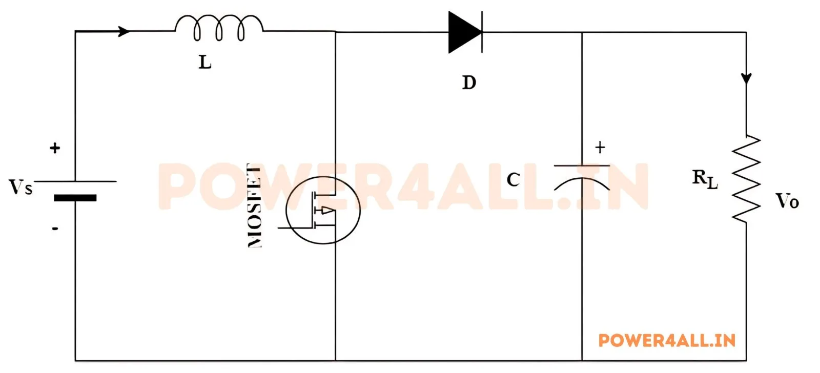
Example 1
Given: Vin=12V, Vout=48V, Pout=120W, Ripple=10%, fsw=50kHz
- Duty Cycle: D = 1 - (12/48) = 0.75 or 75%
- Output Current: Iout = 120/48 = 2.5A
- Input Current: Iin = 2.5/(1-0.75) = 10A
- Inductor Ripple: ΔIL = 0.1×10 = 1A
- Inductor: L = (12×0.75)/(1×50000) = 0.00018 H = 180 μH
- Capacitor: C ≈ 2.08 µF (ΔVout = 4.8V)
- Load Resistor: R = 48/2.5 = 19.2 Ω
Example 2
Given: Vin=24V, Vout=48V, Pout=240W, Ripple=20%, fsw=100kHz
- Duty Cycle: D = 1 - (24/48) = 0.5 or 50%
- Output Current: Iout = 240/48 = 5A
- Input Current: Iin = 5/(1-0.5) = 10A
- Inductor Ripple: ΔIL = 0.2×10 = 2A
- Inductor: L = (24×0.5)/(2×100000) = 0.00006 H = 60 μH
- Capacitor: C ≈ 2.08 µF (ΔVout = 4.8V)
- Load Resistor: R = 48/5 = 9.6 Ω
Example 3
Given: Vin=48V, Vout=96V, Pout=240W, Ripple=15%, fsw=75kHz
- Duty Cycle: D = 1 - (48/96) = 0.5 or 50%
- Output Current: Iout = 240/96 = 2.5A
- Input Current: Iin = 2.5/(1-0.5) = 5A
- Inductor Ripple: ΔIL = 0.15×5 = 0.75A
- Inductor: L = (48×0.5)/(0.75×75000) = 0.000427 H = 427 μH
- Capacitor: C ≈ 0.694 µF (ΔVout = 9.6V)
- Load Resistor: R = 96/2.5 = 38.4 Ω
A boost converter is a switch-mode DC-DC converter that steps a lower input voltage up to a higher regulated output. It is the mirror image of the buck converter and is the go-to circuit whenever a device must run from a supply that is lower than the voltage it needs — for example driving a 12 V rail from a 3.7 V lithium cell.
How it works
The switch first connects the inductor directly across the input, storing energy in its magnetic field as the current ramps up. When the switch opens, that stored energy is released in series with the input, so the two voltages add and push current through a diode into the output capacitor. Because energy is pumped over only part of each cycle, the output can be much higher than the input. The ideal relationship is Vout = Vin / (1 − D), so a duty cycle of 0.5 doubles the voltage and 0.75 quadruples it.
Design considerations
Unlike a buck, the boost draws current from the source continuously through the inductor, and the input current is higher than the output current (power in = power out, so stepping voltage up steps current down at the output). The inductor is sized from the allowed ripple current, and the output capacitor must supply the full load during the switch-on time, so low-ESR capacitors matter. Duty cycles above roughly 0.8–0.9 are avoided because efficiency falls and control becomes difficult as (1 − D) approaches zero.
Where boost converters are used
Battery-powered products (single-cell to 5 V/12 V), LED backlight and flash drivers, power-factor-correction (PFC) front-ends in mains supplies, photovoltaic MPPT stages, and supercapacitor and USB power-delivery circuits. Any time the load voltage sits above the source, a boost is involved.
Common questions
Can a boost converter output a voltage lower than the input? No — even at 0% duty the diode passes the input straight through, so the minimum output is roughly Vin. If you need both step-up and step-down use a buck-boost, SEPIC or ZETA topology.
Why does my input current seem so high? Because the output current is lower than the input current by the voltage ratio; a 3.7 V-to-12 V boost delivering 1 A out draws well over 3 A from the battery.