Single Phase Full Bridge Inverter
A single-phase full bridge inverter is designed to convert DC input into a two-level AC output with full supply voltage, making it ideal for applications ranging from home power backup to industrial motor drives and solar energy systems.
Introduction
The inverter, an electrical device, is utilized to convert a direct current (DC) input supply into an alternating current (AC) voltage of standard magnitude and frequency at the output. The device is also referred to as a DC to AC converter.
In an ideal setting, the input and output of the inverter can be represented by sinusoidal and non-sinusoidal waveforms. When the input source to the inverter is a voltage source, it is designated as a voltage source inverter (VSI); while, when the input source to the inverter is a current source, it is termed as a current source inverter (CSI).
Inverters are categorized into two types based on the type of load being used, namely single-phase inverters and three-phase inverters. Single-phase inverters can be further categorized as half-bridge inverters and full-bridge inverters. This article offers an extensive explanation of the construction and operational principles of a full-bridge inverter.
What is a Single Phase Full Bridge Inverter?
A single phase full bridge inverter is a type of power electronic circuit that takes DC and turns it into AC with two output levels, typically for running household appliances or small machines. It uses four switches-these could be transistors, MOSFETs, or thyristors-arranged in a bridge shape. The switches are turned on and off in pairs: first one diagonal pair, then the other. This alternates the direction of current through the load, creating an AC output.
Unlike the half-bridge inverter, which needs a split (three-wire) DC supply, the full bridge inverter works with a regular two-wire DC supply, making it simpler to connect. Full bridge inverters are popular because they can provide the full supply voltage across the load, offer higher output power, and are more efficient for most single-phase AC applications. The output frequency and waveform can be controlled by adjusting how long each pair of switches is on and off, allowing the inverter to run different types of loads, from simple resistive heaters to motors and electronics.
Circuit Diagram of Single Phase Full-Bridge Inverter
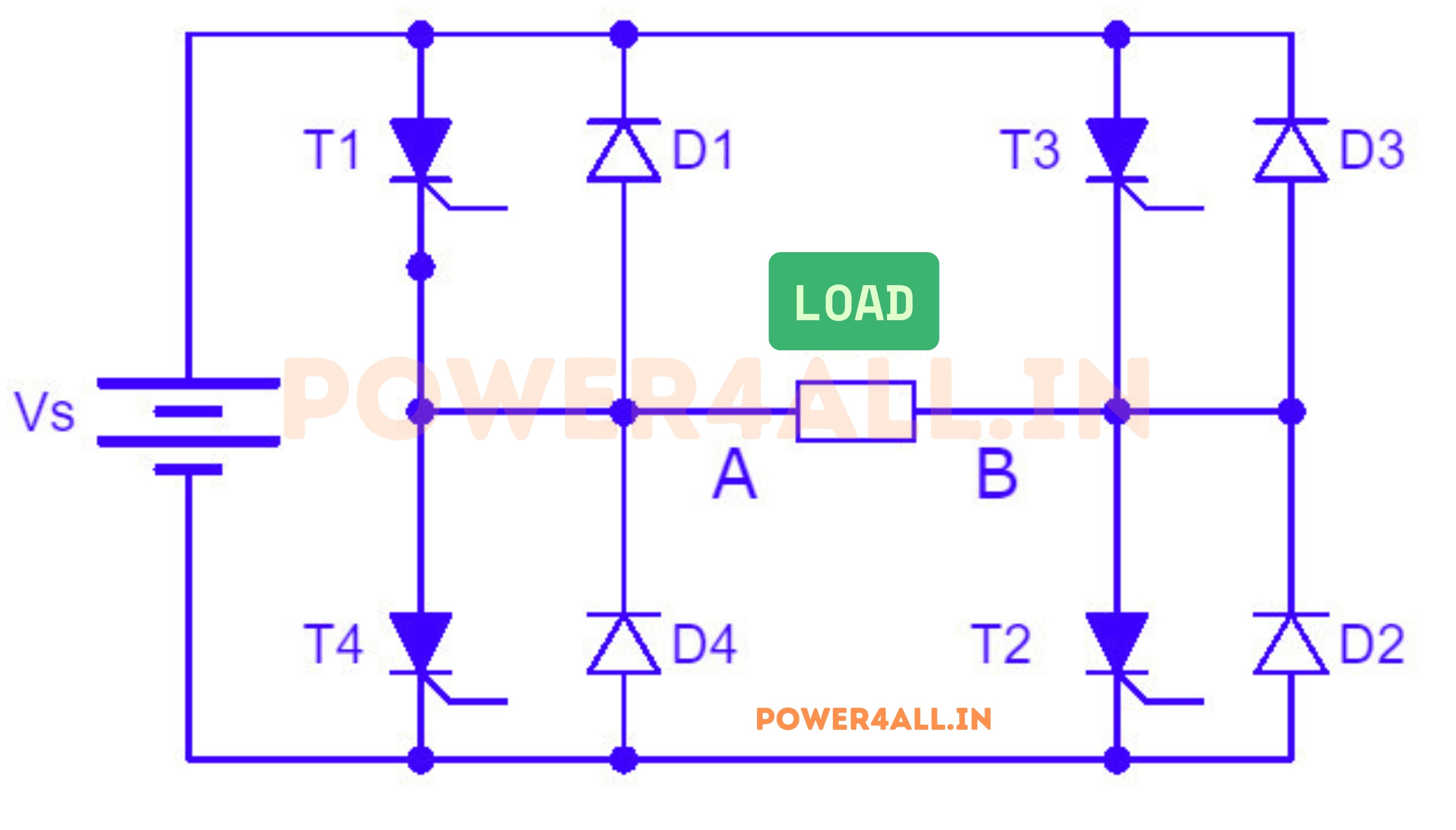
This is a simple diagram of a single-phase full bridge inverter. The main job of this circuit is to convert DC power (from the battery on the left, labeled Vs) into AC power for the load in the middle.
- Vs: This is the DC voltage source, like a battery or a power supply.
- Load (R): This is the device or appliance that uses the AC power, like a light bulb or motor.
- C1 and C2: These are capacitors that help stabilize the voltage and current in the circuit.
- Switches (S1, S2, S3, S4): These are electronic switches (like transistors or MOSFETs) that turn on and off in pairs.
- Diodes (D1, D2, D3, D4): These protect the switches and help with current flow, especially when the load is inductive.
The switches are arranged in a bridge shape. When one pair of switches (S1 and S4) is turned on, current flows through the load in one direction. When the other pair (S2 and S3) is turned on, the current flows in the opposite direction. This switching creates an AC output across the load.
Working Principle of Full Bridge Inverter
This circuit is designed to convert DC to AC for a single-phase system, specifically suitable for single-phase loads. When analyzing this circuit, it is imperative to consider the polarity of the load. If the current flows from point A to point B, it is assumed as positive. Likewise, if point A is positive concerning point B, the voltage is also positive. Adhering to this convention is crucial for comprehending the waveforms and their characteristics.
Case 1: When the switches T1 and T2 are ON
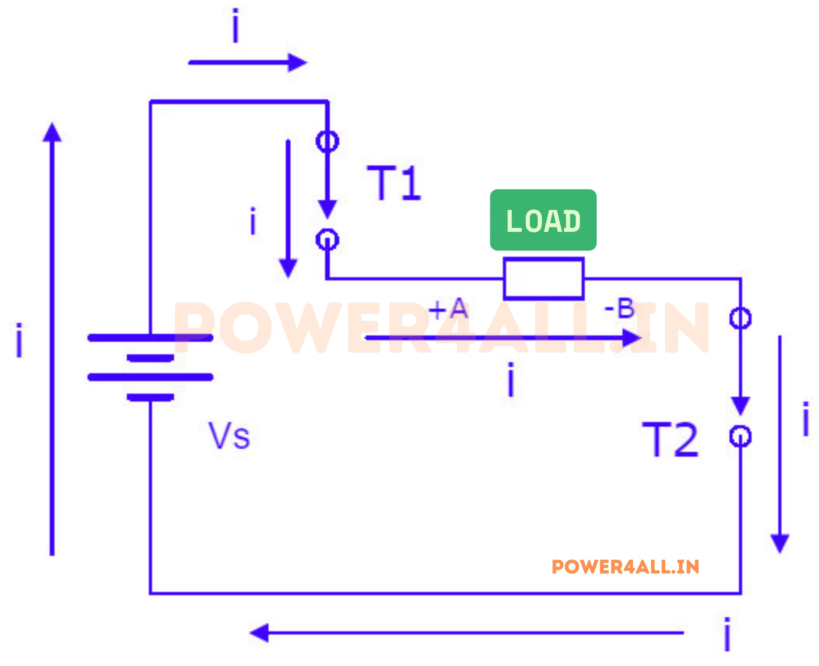
The equivalent circuit appears as depicted. It is imperative to consistently strive to construct an equivalent circuit, as it facilitates the simplified analysis of a circuit. Presently, the current originates from the DC source in a specific direction, with T1 and T2 activated, and T3 and T4 in a deactivated state. Consequently, T1 and T2 establish a short circuit, while T3 and T4 create an open circuit.
Considering "i" as the current flow, the current flows through the following direction: point a - b - c - d. The output voltage will be positive A with respect to B. Consequently, the current will return through this direction: point d - e - f. In summary, the supplied voltage will directly appear across the load terminal due to the short circuit. The supply is directly connected to the load. As a result, output current is positive according to the assumed current convention from A to B. Therefore, the current is also positive.
The output voltage, +VS, is determined by the short circuit direct supply applied to the load terminal. It is essential to note that any voltage input will be directly across the load terminal.
Case 2: When the switches T3 and T4 are ON
In the following scenario, it is assumed that switches T3 and T4 are in the on position, while switches T1 and T2 are turned off, resulting in the circuit configuration illustrated below.
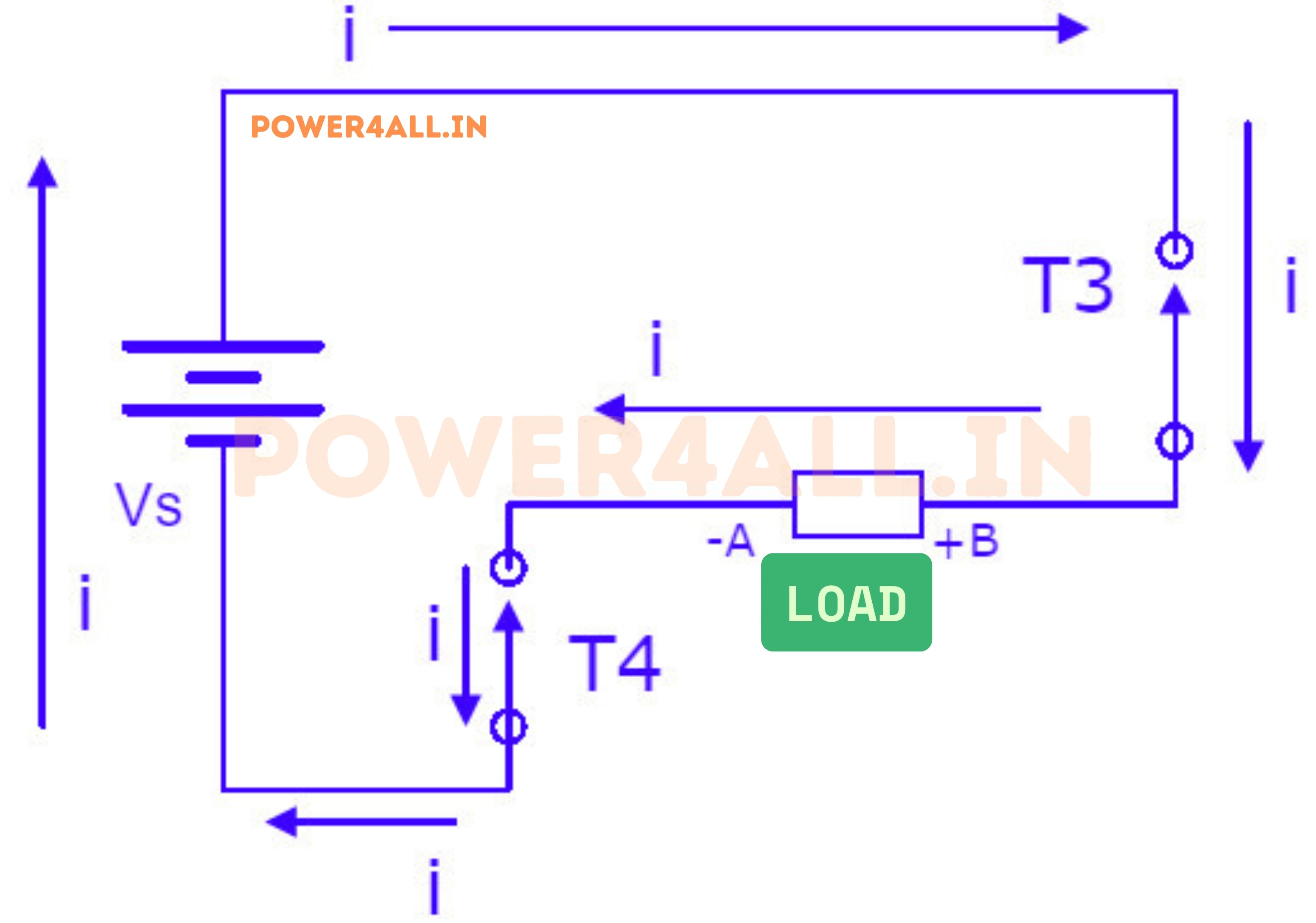
Terminal T3 and T4 are connected to a short circuit, allowing current to flow from point A to point F, and then back to the power source..
In this scenario, the output current is considered negative as it flows from point B to point A, contrary to our established convention. Consequently, the negative direction is acknowledged. Upon close observation, it is apparent that the output voltage also manifests as negative. Therefore, the entirety of VS is supplied and is directly observed across the load terminal..
After careful observation, it is evident that the positive symbol (+) is directly connected to B, signifying a positive correlation, while the negative symbol (-) is directly connected to A. Consequently, the resulting output voltage is determined to be equal to -VS.
While analyzing the circuit, a critical consideration is the conversion of DC to AC, which can be elucidated through waveforms. Notably, the triggering of T1 and T2 will be conducted, followed by their deactivation for the remaining duration. Subsequently, T3 and T4 will be activated only when T1 and T2 are turned off. It is imperative to observe this sequence as simultaneous activation of these components could result in a short circuit, thereby impeding the output and potentially damaging the power supply.
Waveform of Single-Phase Full Bridge Inverter
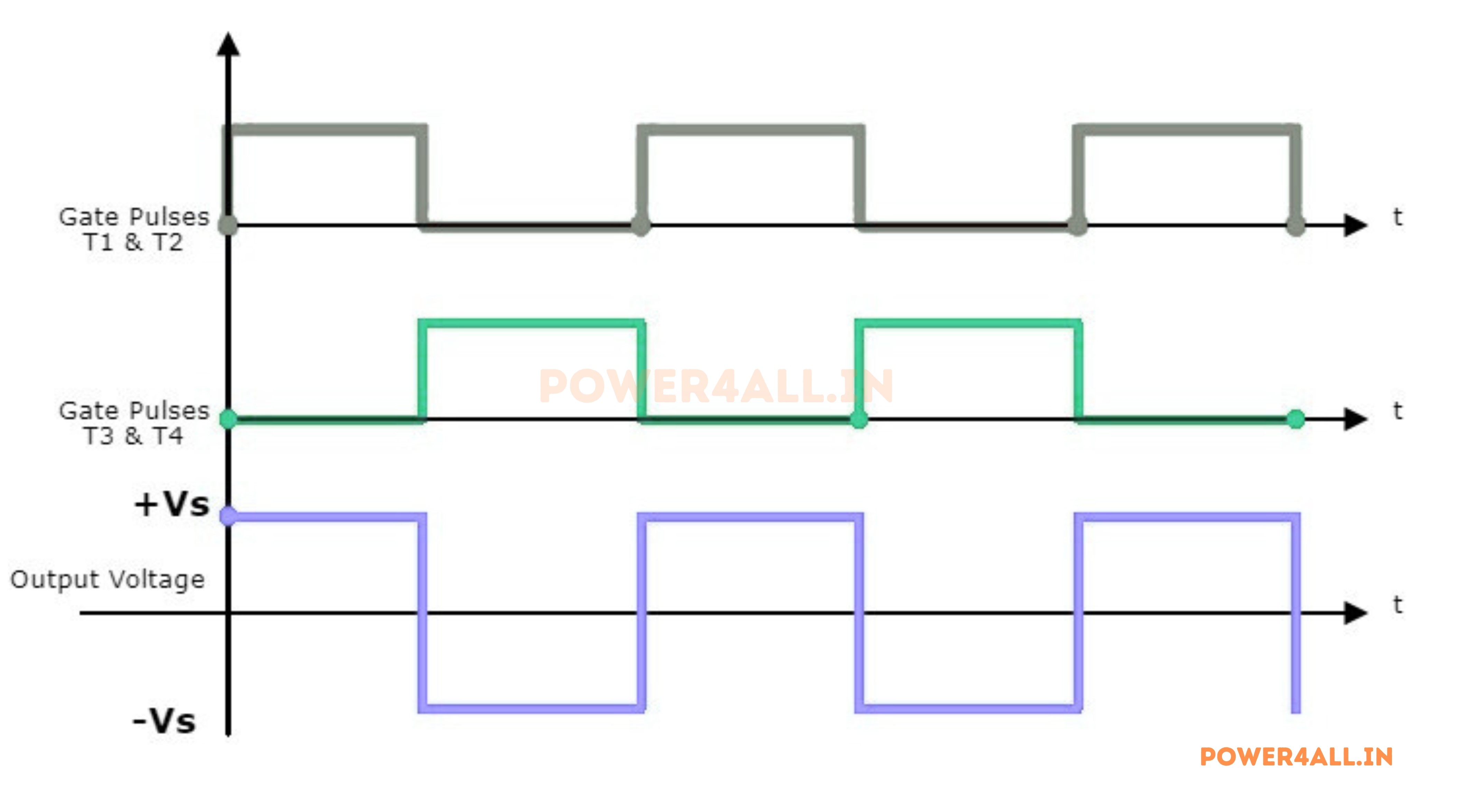
So it looks like this, when T1 and T2 are turned on and the output voltage is (+) VS. Consequently once T1 and T2 are turned off and T3 and T4 are turned on, the voltage or current will immediately change to (-) VS according to the inference that we have noted down with respect to case 2.
Again in the next cycle, when T1 and T2 are triggered, the output voltage will be equal to (+) VS. The voltage across the load will basically be the supply voltage, so it changes instantly. As a result, there will be no deviations where it increases slowly or decreases slowly. So this is for a resistive load, as a result, it will change instantly.
The output voltage will be a square wave. The output voltage will be equal to the supply voltage, so it changes instantly. As a result, there will be no deviations where it increases slowly or decreases slowly. So this is for a resistive load, as a result, it will change instantly.
Advantages
- There is minimal fluctuation of voltage in the circuit.
- It is also suitable for high input voltage.
- Energy-Efficient.
- The current rating of the circuit is equal to the load current.
- It drives slightly more voltage ripples than a half-bridge inverter.
Disadvantages
- The efficiency of the full bridge inverter ( 95% ) is less than the half-bridge inverter (99%).
- Losses and noise are high, so it requires more switching elements.
- The full bridge inverter is more complex than the half-bridge inverter.
- It is analogous to the half-bridge inverter. However, it’s an extra segment to attach the ground point to the load.
Applications
- This is used in the application of a higher voltage requirement.
- It can be applicable in low and medium power example square wave / quasi square wave voltage.
- Solar inverters can use this type of power inverter.
- It also uses in these types of devices like AC variable motors, heating induction devices, standby power supplies etc.