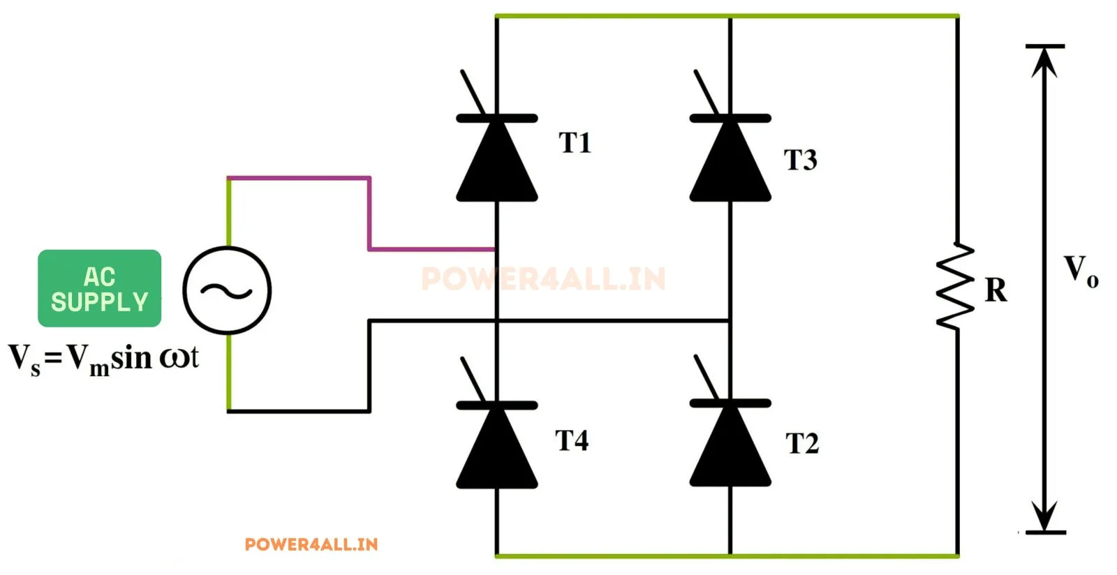
What is a single-phase full-wave controlled rectifier?
A single-phase full-wave fully-controlled rectifier is a bridge of four thyristors (SCRs). The diagonal pairs T1·T2 and T3·T4 are triggered alternately at the firing angle α, so both halves of the AC supply are used and the load always receives current in the same direction. Unlike a diode bridge, the firing angle lets you set the DC output — and because there is no freewheeling path, the output voltage can go negative, giving true two-quadrant operation.
Output voltage equations
The average output depends on the conduction mode:
With a highly inductive load the current never stops, so the output follows the supply even when it is negative and Vdc = (2Vm/π)cos α. This is positive for α < 90° (rectifying) and negative for α > 90° (inverting). With a purely resistive load the current stops at every zero crossing, the output cannot go negative, and Vdc = (Vm/π)(1 + cos α). The simulator detects the conduction mode automatically and checks the correct formula.
Two-quadrant operation & inversion
For α > 90° the average output voltage is negative. If the load contains an active source (for example a DC-motor back-EMF, set a negative E in the simulator), the current keeps flowing and power flows from the DC side back to the AC supply — line-commutated inversion. This is exactly how a DC drive performs regenerative braking. A purely passive load cannot invert, so its current simply becomes discontinuous for large α — you can see both behaviours in the simulator.
Advanced options in this simulator
- SCR model: add a forward drop
V_fand on-resistanceR_on; the bridge conducts through two SCRs in series so the drop is2·V_f + 2·R_on·i. The accuracy check stays locked to the ideal envelope. - Transformer: a turns ratio scales the peak voltage
Vmapplied to the bridge. - Filter & protection: a series-L, shunt-C or LC output filter, an optional RC snubber, and a live protection-margin check of the SCR peak voltage (PIV vs V_RRM) and average current (vs I_T(av)).
- Harmonic spectrum analysis: a real FFT of the output voltage or load current with the ripple / THD figure (relative to |DC|, so it works in inversion too).
- Export & capture: download the full waveform data as CSV, a text report, or a PNG screenshot of the scope.
Full converter vs semi-converter
| Feature | Full converter (4 SCR) | Semi-converter (2 SCR + 2 diode) |
|---|---|---|
| Average voltage | (2Vm/π)cos α | (Vm/π)(1 + cos α) |
| Quadrants | Two (rectify + invert) | One (rectify only) |
| Output polarity | Can go negative | Always ≥ 0 |
| Freewheeling | None (by design) | Inherent |
| Input power factor | Lower (displacement = α) | Higher (≈ α/2) |
Compare with the single-phase semi-converter simulator.
Applications
DC-motor drives with regenerative braking, battery charging, electrochemical processes, HVDC-style line-commutated converters, and any application needing a bidirectional (rectify/invert) controllable DC link from a single-phase AC supply.
Frequently asked questions
What is the average output voltage of a full-wave controlled rectifier?
For continuous (inductive) conduction, Vdc = (2Vm/π)cos α. For a resistive load the output is discontinuous and Vdc = (Vm/π)(1 + cos α).
When does the converter invert?
For α > 90° the average voltage is negative. If the load has an active source (e.g. a motor back-EMF), power flows back to the AC supply — line-commutated inversion, used in regenerative braking.
Why is there no freewheeling diode?
A fully-controlled bridge deliberately omits the freewheeling diode so the output can go negative for inversion. Adding one clamps the output to zero on the negative half and makes it a one-quadrant converter like a semi-converter.
How is it different from a semi-converter?
A full converter uses four SCRs and works in two quadrants with Vdc = (2Vm/π)cos α; a semi-converter uses two SCRs and two diodes, works in one quadrant with Vdc = (Vm/π)(1 + cos α) and has a better power factor.
What causes discontinuous conduction?
A resistive or lightly-inductive load lets the current fall to zero before the next pair is fired. The simulator flags CCM (continuous) or DCM (discontinuous) and uses the matching formula.
What does the harmonic spectrum show?
An FFT of the output voltage (or load current). The ripple is dominated by the 2nd harmonic (2f) as in an uncontrolled bridge, but raising the firing angle α increases the overall harmonic content and THD. Switch between the voltage and current spectra and choose how many harmonics to display.