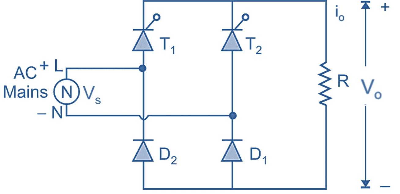
What is a single-phase semi-converter?
A single-phase semi-converter, also called a half-controlled bridge rectifier, is an AC-to-DC power converter built from two thyristors (SCRs) and two diodes. The thyristors — T1 and T2 — give you control over the average DC output voltage through the firing angle α, while the diodes D1 and D2 (together with the natural freewheeling action) prevent the output voltage from ever becoming negative. This makes the semi-converter a one-quadrant converter: it delivers an adjustable positive voltage and positive current, but it cannot return power to the AC source.
Compared with a fully-controlled bridge (four thyristors), the semi-converter is cheaper, needs a simpler gate-drive circuit, and — thanks to freewheeling — draws a source current with a better input power factor at the same firing angle. It is widely used in DC motor speed control, battery charging, electroplating, and adjustable DC power supplies.
How it works — modes of operation
With the peak supply voltage Vm and supply vₛ = Vm·sin(ωt), the converter passes through four intervals every cycle:
- 0 → α (freewheel): the load current from the previous half-cycle freewheels through T2 and D1; output
v₀ = 0, source currentiₛ = 0. - α → π (powering, positive half): thyristor T1 is fired and conducts with diode D1; the load sees
v₀ = vₛand the source deliversiₛ = +i₀. - π → π+α (freewheel): the supply reverses, so the inductive load current freewheels through T1 and D2; output
v₀ = 0again. - π+α → 2π (powering, negative half): thyristor T2 is fired and conducts with diode D2; the load sees
v₀ = |vₛ|andiₛ = −i₀.
So each thyristor conducts for 180° (from its firing instant to the next thyristor's firing), while each diode commutates naturally at the supply zero-crossings. You can see all of this in the simulator's conducting-devices strip and the individual iT1, iT2, iD1, iD2 current traces.
Output voltage & current equations
The average (DC) and RMS output voltages of a single-phase semi-converter are independent of the load type:
At α = 0, the converter behaves like an uncontrolled full-wave rectifier with Vdc = 2Vm/π ≈ 0.637·Vm. As α increases, Vdc falls smoothly to zero at α = 180°. For a highly inductive load the average load current is simply Idc = Vdc / R (with a back-EMF load, Idc = (Vdc − E) / R). This simulator does not plug numbers into these formulas to draw the curves — it integrates L·di/dt = v₀ − R·i − E through the real device states, reaches steady state, and then measures Vdc and Vrms from the samples, comparing them to the equations above so you can trust the waveforms.
Symmetrical vs asymmetrical configuration
Two circuit layouts give identical output voltage:
| Symmetrical semi-converter | The two thyristors share a common cathode and the two diodes share a common anode (shown in the circuit above). Both cathodes sit on the positive output rail, simplifying the gate-drive supply. |
|---|---|
| Asymmetrical semi-converter | Each leg of the bridge contains one thyristor and one diode. The SCRs do not share a common cathode, so isolated gate drives are required, but device stress is distributed differently. |
Semi-converter vs full-converter
| Feature | Semi-converter (half-controlled) | Full-converter (fully-controlled) |
|---|---|---|
| Devices | 2 SCR + 2 diode | 4 SCR |
| Average voltage | (Vm/π)(1 + cos α) | (2Vm/π) cos α |
| Output polarity | Positive only (1-quadrant) | Can go negative (2-quadrant, inversion) |
| Freewheeling | Inherent (built-in) | None (needs external FWD) |
| Input power factor | Higher (displacement ≈ α/2) | Lower (displacement = α) |
| Regeneration | Not possible | Possible (α > 90°) |
Advanced options in this simulator
- Device model: add a forward drop
V_fand on-resistanceR_on; each conduction path is one SCR + one diode, so the total drop is2·V_f + 2·R_on·i. The accuracy check stays locked to the ideal(Vm/π)(1+cos α)envelope. - Transformer: a turns ratio scales the peak voltage
Vmapplied to the converter. - Filter & protection: a series-L, shunt-C or LC output filter, an optional RC snubber, and a live protection-margin check of the device PIV (= Vm) and average current against the ratings you enter.
- Harmonic spectrum analysis: a real FFT of the output voltage or load current with the ripple / THD figure, alongside the existing source-current power-factor and THD readouts.
- Export & capture: download the full waveform data as CSV, a text report, or a PNG screenshot of the scope.
Adding an output filter (L, C or LC)
The raw semi-converter output is a chopped, ripply DC. A low-pass output filter smooths it before it reaches the load:
- Series inductor (L / choke-input): opposes changes in current, so it smooths the load current and forces continuous conduction. On its own it barely changes the average voltage — a choke has zero average volt-drop.
- Shunt capacitor (C / capacitor-input): holds the output voltage near the peak of the supply, cutting voltage ripple sharply and raising the average toward
Vm(peak charging), at the cost of pulsed, spiky input current. - LC filter: a series L followed by a shunt C gives the best of both — strong ripple attenuation with well-behaved current. Ripple falls with the square of the ratio of switching to LC-resonant frequency.
This simulator models the filter exactly — it integrates the real filter differential equations rather than applying an approximate factor — so the load-voltage average, ripple and current spikes you see are physically correct. Try the filter presets and watch the Load ripple reading drop.
Advantages & applications
Advantages: fewer controlled devices and lower cost, simpler triggering, inherent freewheeling, and an improved input power factor versus a full converter. Limitations: one-quadrant operation only (no regeneration), and higher output-voltage ripple at large firing angles.
Applications: DC motor speed control, battery charging, electroplating and electrolysis, traction auxiliaries, adjustable DC power supplies, and any load that needs a controllable positive DC voltage from a single-phase AC mains.
Frequently asked questions
What is the average output voltage of a single-phase semi-converter?
The average DC output voltage is Vdc = (Vm/π)(1 + cos α), where Vm is the peak supply voltage and α is the firing angle. It equals 2Vm/π at α = 0° and falls to zero at α = 180°.
Why does a semi-converter have a better power factor than a full converter?
Freewheeling makes the input current sit in phase with the supply for longer, so its fundamental component is displaced by only about α/2, versus the full α of a fully-controlled bridge. The smaller displacement angle raises the input power factor — you can confirm this in the simulator's Power factor and Displacement factor readouts.
What is the freewheeling action in a semi-converter?
When the supply reverses, the inductive load current keeps circulating through a diode and the still-conducting thyristor, short-circuiting the load. During this interval the output voltage is clamped to zero and no current is drawn from the source — visible as the flat v₀ = 0 segments and the zero-current notches in iₛ.
Does the semi-converter work with a resistive load?
Yes. With a pure-R load the output current simply follows the output voltage and is discontinuous. With an R-L load the current becomes smoother and, for a large inductance, nearly constant. Switch the load type in the simulator to compare.
Can a single-phase semi-converter invert (return power to the AC source)?
No. Because the diodes and freewheeling prevent the output voltage from going negative, the semi-converter is a one-quadrant converter and cannot operate in the inversion mode. A fully-controlled converter is required for regeneration.
What does the harmonic spectrum show?
An FFT of the output voltage (or load current). Raising the firing angle α increases the harmonic content and THD. Switch between the voltage and current spectra and choose how many harmonics to display.