SEPIC Converter
The primary function of a SEPIC converter is to step up or step down voltage from a lower level to a higher level.
- Introduction
- DC-DC SEPIC CONVERTER
- Working Principle of SEPIC Converter
- Mode I: Switch S is ON and Diode D is OFF.
- Mode II: Switch S is OFF and Diode D is ON.
- Waveform of SEPIC Converter
- Advantages of SEPIC Converter
- Disadvantages of SEPIC Converter
- Applications of SEPIC Converter
- Conclusion
- Frequently Asked Questions About SEPIC Converter – FAQs
- Related Topics
Introduction
In the world of power electronics, the SEPIC converter stands out as a versatile and practical solution for voltage regulation challenges. Short for Single-Ended Primary-Inductor Converter, this unique circuit design allows engineers to either increase or decrease input voltage while maintaining the same polarity - a feature that makes it incredibly useful when working with fluctuating power sources.
The SEPIC converter bridges the gap between basic Buck and Boost topologies, offering the best of both worlds without the polarity inversion that plagues traditional Buck-Boost designs. This makes it particularly valuable in battery-powered applications, where the supply voltage gradually decreases as the battery discharges. With a SEPIC converter, your circuit can maintain stable output voltage throughout the entire discharge cycle without complex switching between different converter types.
What I find most interesting about SEPIC converters is their elegant use of coupled inductors and a transfer capacitor to achieve their voltage conversion magic. While slightly more complex than basic converters, this design provides benefits like reduced noise and continuous input current - crucial advantages in sensitive electronic systems. From portable medical devices to solar charge controllers, the SEPIC converter has become an essential tool for engineers tackling real-world power management challenges where input voltage can swing both above and below the desired output level.
DC-DC SEPIC CONVERTER
SEPIC stands for Single-Ended Primary-Inductor Converter. It is a type of DC-to-DC converter that can accept a range of DC input voltages and deliver a stable output voltage. This converter operates similarly to Buck-Boost and Cuk converters by providing an output voltage that can be greater than, less than, or equal to the input voltage.
The SEPIC converter, akin to the Buck-Boost converter, amalgamates the functionalities of both Buck and Boost converters. In contrast to the buck-boost converter, the SEPIC converter presents various advantages. These encompass consistent polarities of input and output voltages, elevated efficiency, and the capacity for the capacitor to isolate the input and output sides.
Buck converter for voltage reduction and a boost converter for voltage increase. An alternative topology involves the use of a Buck-Boost converter, providing adjustable voltage step-up or step-down capabilities. This converter uniquely yields output with an inverted polarity. The Cuk converter operates on a similar principle to the Buck-Boost converter, but with an output polarity reversal. Common DC-DC converters, such as the buck, boost, and buck-boost, consist of one capacitor, one inductor, one diode, and one semiconductor switch. Contrastingly, the Cuk converter architecture comprises two inductors, two capacitors, a diode, and a semiconductor switch, resulting in reduced voltage ripple on both input and output sides. A detailed exploration of the Cuk converter's topology will be presented in this section.
Working Principle of SEPIC Converter
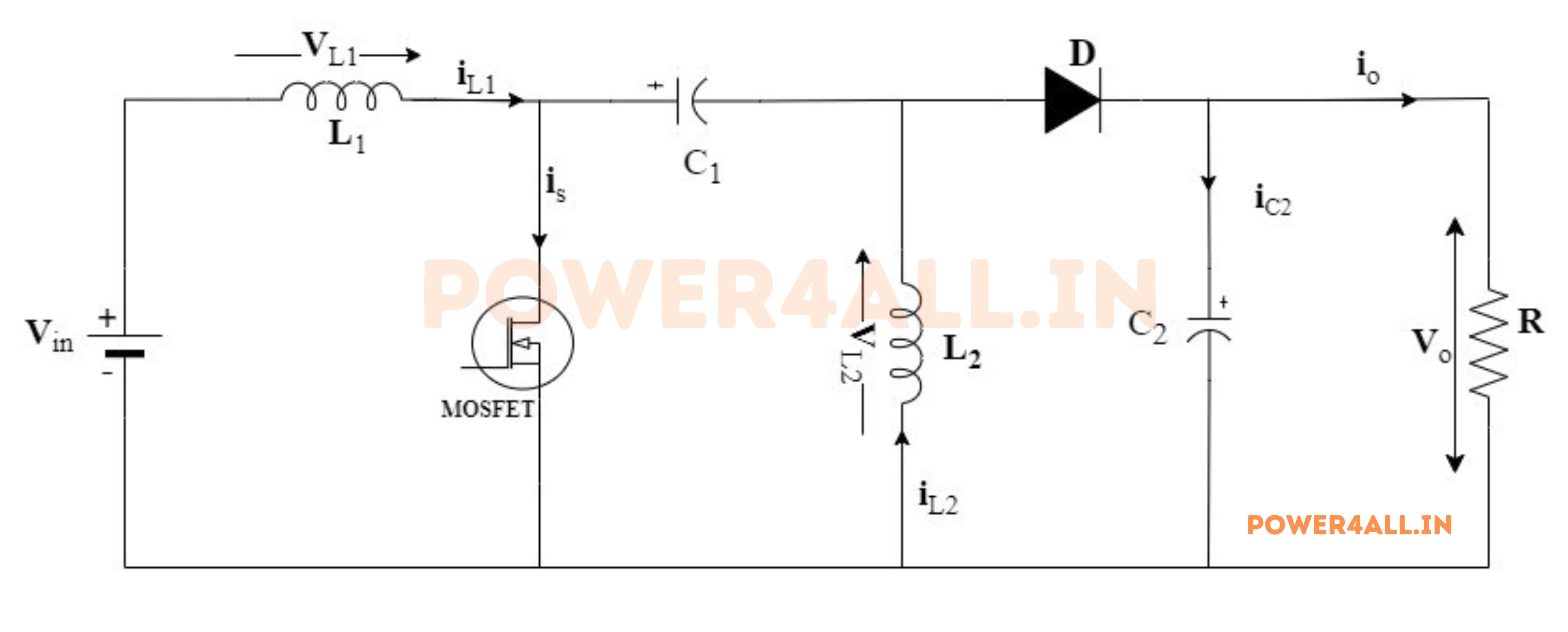
The diagram below illustrates the schematic of a fundamental single-ended primary-inductor converter (SEPIC). Similar to buck-boost and Cuk converters, the SEPIC converter employs inductors and capacitors to achieve regulated output.
The circuit diagram for a typical SEPIC converter is shown in the figure below.
here are two modes of operation of the SEPIC converter. They are:
Mode I: When the switch S is ON
When the application of a gate pulse activates the Metal-Oxide-Semiconductor Field-Effect Transistor (MOSFET), the source current initiates a flow through inductor L1, the MOSFET, and back to the source. This sequential flow causes the current IL1 in the inductor to increase, thereby commencing the inductor's charging process from the input source.
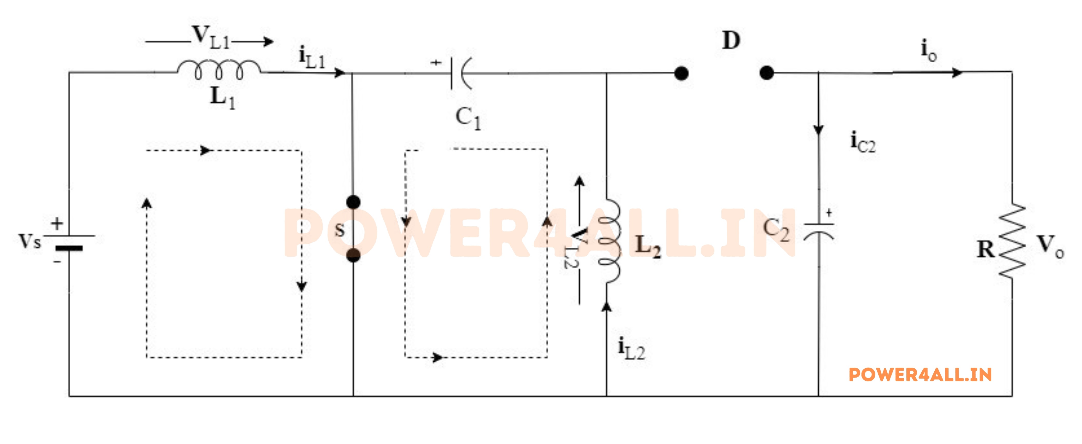
During the charging process of inductor L1, the instantaneous voltage VL1 across inductor L1 will approximate the source voltage Vin. Additionally, while the MOSFET is conducting, inductor L2 will be energized by the release of energy from capacitor C1. The energy stored in capacitor C1 will be transferred to inductor L2 through the MOSFET, as depicted above.
Mode II: Switch S is OFF and Diode D is ON
Upon deactivation of the MOSFET through the cessation of the gate pulse, the inductor L1 functions to impede abrupt changes in current, causing the inductor's polarity to reverse in accordance with Lenz's law. Consequently, the inductor commences discharging in the opposite direction, transferring its energy to capacitor C1 as depicted below.
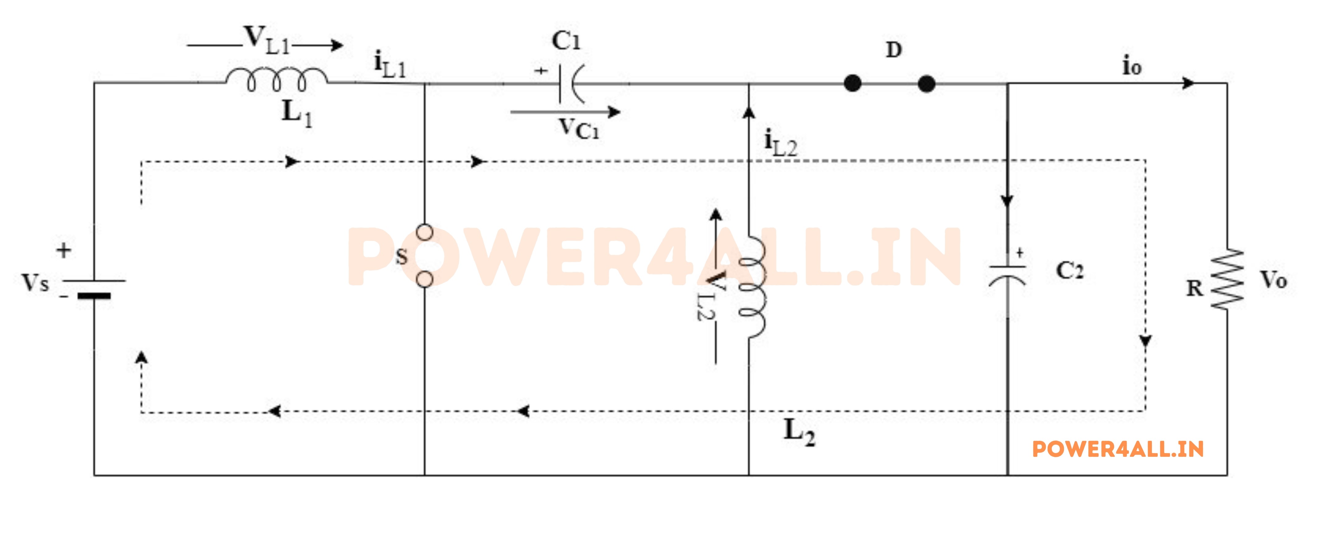
Upon the activation of the MOSFET, the previously discharged capacitor C1 will commence recharging. Consequently, the charged inductor L2 will undergo reverse discharge, leading to diode forward biasing. This will facilitate the transfer of the dissipated energy from inductor L2 to the load.
Upon activation of the MOSFET, the cycle initiates once more, leading to the charging of inductors L1 and L2 by the power source and capacitor C1, respectively. The operation of the SEPIC converter can be classified into either discontinuous conduction mode or continuous conduction mode, contingent on the reduction of current flow through the inductors to zero or not.
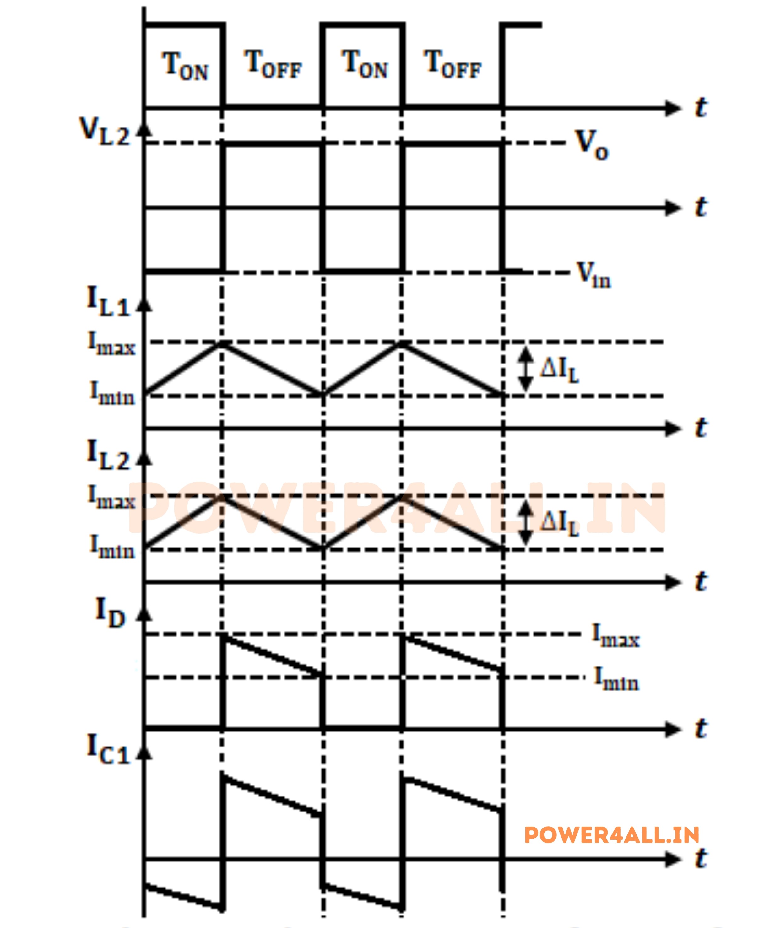
Waveform of SEPIC Converter
The waveform of a SEPIC converter is characterized by its distinct voltage and current profiles during the two operational modes. The following figure illustrates the voltage and current waveforms associated with the SEPIC converter's operation.
Advantages of SEPIC Converter
The SEPIC converter offers several advantages, making it a popular choice in various applications:
- In buck-boost and Cuk converters, the output voltage exhibits an inverted polarity in relation to the input voltage. Conversely, in the SEPIC converter, the output voltage maintains the same polarity as the input voltage.
- Capacitor C1 effectively separates the input and output sides, ensuring that any abnormal condition on one side of the circuit does not impact the other side.
- Reduced input current ripple.
- The operation of CUK and buck-boost converters inflict a significant amount of electrical stress on the components, a challenge which can be effectively addressed through the employment of a SEPIC.
- High efficiency and stable operation.
- The implementation of a coupled inductor, as opposed to using two individual inductors wound onto a single core, contributes to a more compact circuit design.
Disadvantages of SEPIC Converter
While SEPIC converters have many advantages, they also have some disadvantages:
- Similar to the Buck-Boost converter, the SEPIC converter can exhibit a pulsating output current, whereas the Cuk converter ensures a continuous output current.
- To ensure that all current from the source to the load is properly managed, it is imperative that capacitor C1 possesses a high capacitance and robust current handling capability.
- Given that the voltage across capacitor C1 reverses with each cycle, it is essential for it to be of a non-polarized nature.
Applications of SEPIC Converter
SEPIC converters find applications in various fields, including:
- Power supplies for battery-operated devices, where the input voltage can vary widely.
- LED drivers, providing constant current to LEDs.
- Solar power systems, particularly in Maximum Power Point Tracking (MPPT) applications.
- Telecommunications equipment, where low noise and ripple are critical.
- Automotive electronics, including electric vehicle power management systems.
- Medical devices, where stable voltage is crucial for sensitive electronics.
Conclusion
In conclusion, the SEPIC converter is a versatile and efficient DC-DC converter topology that can step up or step down voltage while maintaining the same polarity. Its unique design allows for continuous input and output currents, making it suitable for various applications, especially in battery-powered devices and renewable energy systems. While it has some disadvantages, its advantages often outweigh them, making it a valuable tool in power electronics.