Complete Electric Current Mastery Guide
Master the fundamentals of electric current, from basic electron flow to advanced applications in modern electronics and power systems
Complete Learning Path - Current Fundamentals to Applications
Navigate through comprehensive coverage of current from basic principles to advanced applications
What is Electric Current?
Electric current is the flow of electric charge through a conductor, similar to how water flows through a pipe. It's the movement of electrons (or other charge carriers) that enables all electrical devices to function, from the smallest microchip to massive industrial motors.
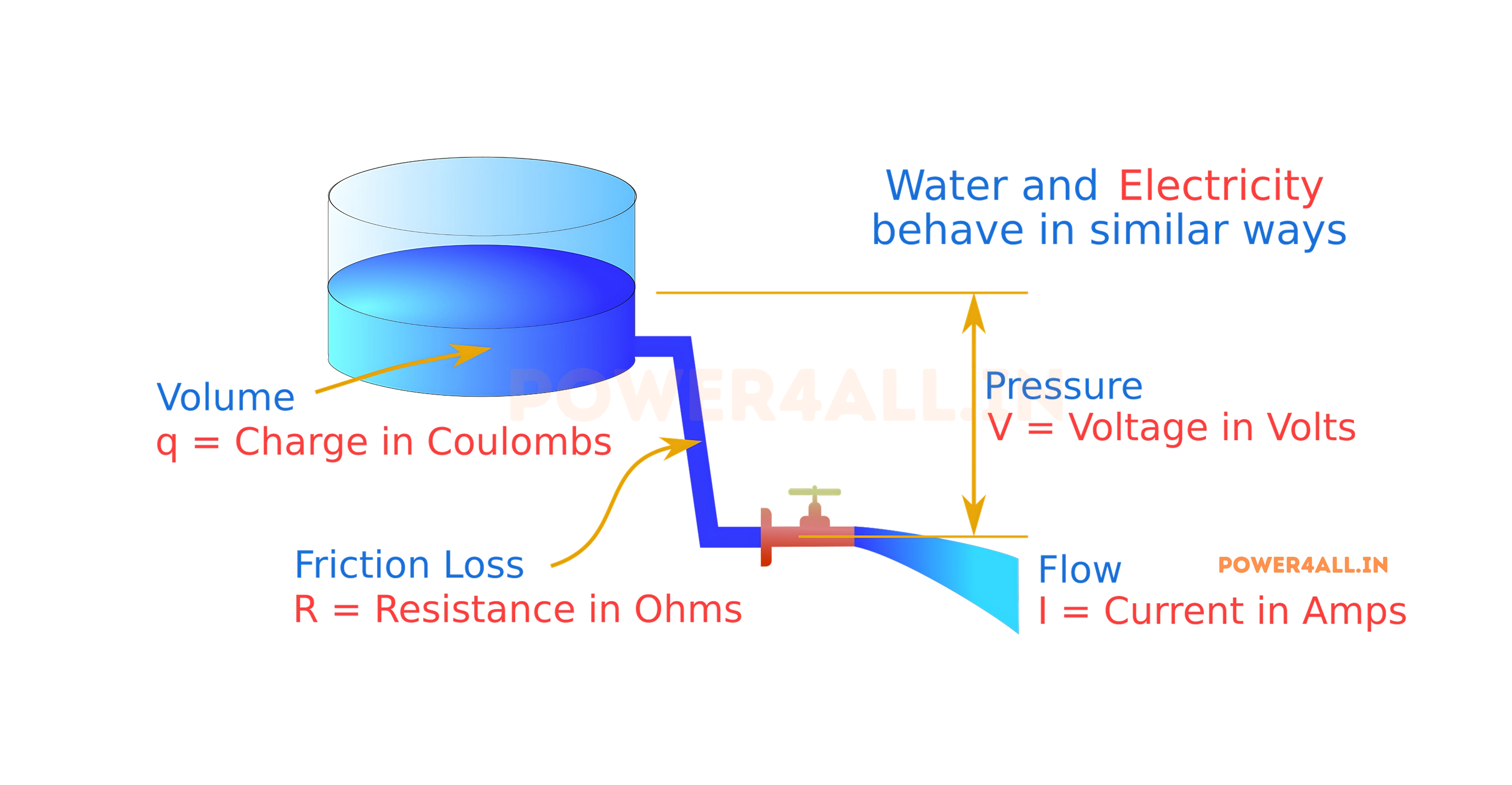
The Water Flow Analogy
Think of current like water flowing through a garden hose. Just as water flow rate is measured in gallons per minute, current is measured as charge flow per unit time.
Perfect Comparison
- Water flow rate → Electric current (charge flow rate)
- Water pressure → Voltage (electrical pressure)
- Pipe diameter → Wire size (conductor capacity)
- Pipe restrictions → Electrical resistance
I = Q / t
Current (I) equals Charge (Q) divided by Time (t)
Scientific Definition
Current is defined as the amount of electric charge that passes through a cross-section of a conductor per unit time. It's measured in amperes (A), named after André-Marie Ampère, a French physicist who made fundamental contributions to electromagnetism.
Key Understanding
One ampere equals one coulomb of charge flowing past a point in one second. To put this in perspective, one coulomb contains approximately 6.24 × 10¹⁸ electrons - that's over 6 billion billion electrons!
Current Direction: Conventional vs Electron Flow
Conventional Current
Definition: Flow from positive to negative terminal
- Historical basis: Established before electron discovery
- Standard usage: Used in circuit analysis and design
- Direction: Opposite to actual electron movement
- Practical application: All circuit laws work with this convention
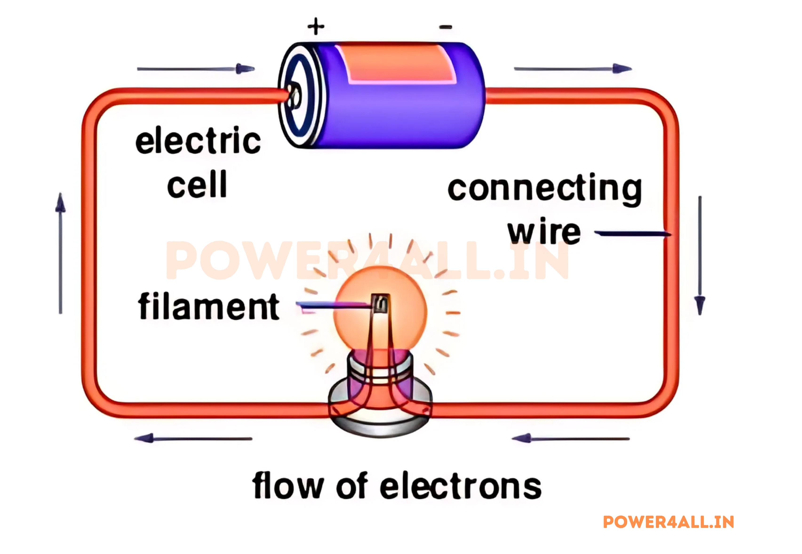
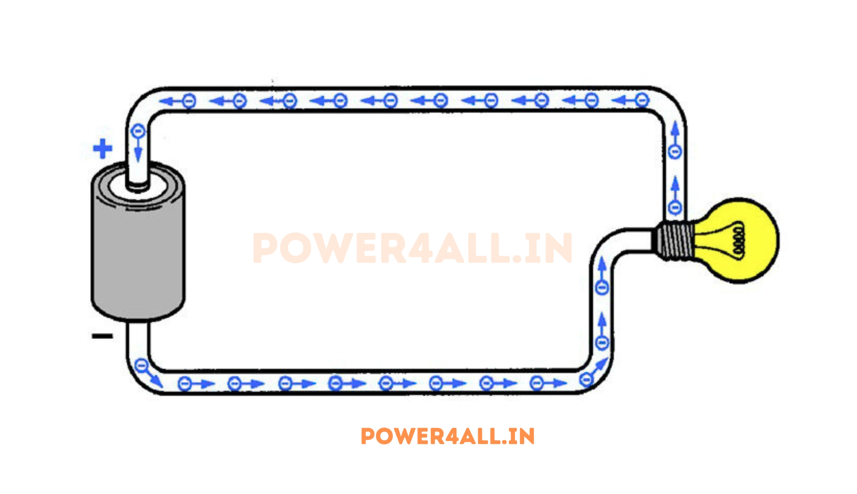
Electron Flow
Definition: Actual movement of electrons from negative to positive
- Physical reality: How electrons actually move in conductors
- Negative charge: Electrons are negatively charged particles
- Direction: From negative terminal to positive terminal
- Understanding: Helps explain physical mechanisms
Why Current is Essential
Energy Transfer
Current is the mechanism by which electrical energy is transferred from sources to loads. Without current flow, no work can be done by electrical devices.
Information Processing
In digital systems, controlled current flow represents information. Binary data, processing operations, and memory storage all depend on precise current control.
Mechanical Work
Electric motors convert current flow into mechanical motion. The interaction between current and magnetic fields produces the forces that drive countless machines.
Heat Generation
Current flow through resistance produces heat (Joule heating). This principle enables electric heaters, incandescent bulbs, and even welding applications.
Current in Different Materials
| Material Type | Charge Carriers | Current Mechanism | Typical Applications | Special Properties |
|---|---|---|---|---|
| Metals | Free electrons | Electron drift in conduction band | Wires, contacts, circuit boards | Low resistance, high conductivity |
| Semiconductors | Electrons and holes | Band-to-band conduction | Diodes, transistors, solar cells | Controllable conductivity |
| Electrolytes | Ions (positive and negative) | Ion migration in solution | Batteries, electroplating | Chemical reactions at electrodes |
| Plasma | Electrons and positive ions | Charge separation and flow | Fluorescent lights, welding | High-temperature conduction |
| Superconductors | Cooper pairs (electron pairs) | Zero-resistance quantum flow | MRI machines, power cables | Zero electrical resistance |
Amazing Current Facts
- Lightning current: Can reach 30,000 amperes for microseconds
- Human nervous system: Operates on currents of nanoamperes to microamperes
- Electric eel: Can generate currents up to 1 ampere at 600 volts
- Household circuits: Typically protected at 15-20 amperes
- Car starter motor: Can draw 100-400 amperes during starting
- LED current: Modern LEDs operate efficiently at 20-350 milliamperes
Current Fundamentals: Deep Understanding
Understanding current fundamentals involves exploring the microscopic behavior of charge carriers, the relationship between current and other electrical quantities, and the factors that influence current flow in different materials and conditions.
Microscopic View of Current Flow
Electron Motion in Conductors
In metallic conductors, current flow involves the coordinated movement of free electrons through a crystal lattice of positive ions. This process is more complex than simple electron movement.
Drift Velocity vs Random Motion
Random Thermal Motion
- Speed: ~10⁶ m/s at room temperature
- Direction: Completely random, no net movement
- Energy source: Thermal energy from temperature
- Effect on current: Zero net contribution
Drift Velocity
- Speed: ~10⁻⁴ m/s (very slow)
- Direction: Consistent toward positive terminal
- Energy source: Applied electric field (voltage)
- Effect on current: Creates net charge flow
I = n × A × v × q
Current = charge density × area × drift velocity × charge per carrier
Drift Velocity Calculation
Example: 10A current in 12 AWG copper wire
- Wire cross-section: A = 3.31 mm² = 3.31 × 10⁻⁶ m²
- Free electron density: n = 8.5 × 10²⁸ electrons/m³
- Electron charge: q = 1.6 × 10⁻¹⁹ C
- Drift velocity: v = I/(n×A×q) = 2.2 × 10⁻⁴ m/s = 0.22 mm/s
- Implication: Electrons move less than 1 mm per second!
Why Lights Turn On Instantly
Although individual electrons move very slowly, the electric field that causes their motion propagates at nearly the speed of light. When you flip a switch, the field change reaches all electrons in the circuit almost instantly, causing immediate current flow throughout the entire circuit.
Current Units and Measurements
| Unit Name | Symbol | Value in Amperes | Common Applications | Typical Range |
|---|---|---|---|---|
| Ampere | A | 1 | Household appliances, motors | 0.1A - 100A |
| Milliampere | mA | 10⁻³ | LEDs, small electronics | 1mA - 1000mA |
| Microampere | μA | 10⁻⁶ | Sensors, precision circuits | 1μA - 1000μA |
| Nanoampere | nA | 10⁻⁹ | Ultra-low power devices | 1nA - 1000nA |
| Kiloampere | kA | 10³ | Industrial processes, welding | 1kA - 100kA |
Historical Context
The ampere is one of the seven SI base units. It was originally defined as the current that produces a specific force between two parallel conductors, but since 2019, it's defined based on the elementary charge and the second, making it more fundamental and stable.
Factors Affecting Current Flow
Temperature Effects
In metals, higher temperature increases resistance and decreases current for a given voltage. In semiconductors, higher temperature can increase current due to more charge carriers.
Cross-Sectional Area
Larger conductor cross-section allows more current flow, like a wider pipe allows more water flow. Current density (A/m²) is often more important than total current.
Conductor Length
Longer conductors have higher resistance, reducing current for a given voltage. This is why power transmission uses high voltages to maintain current over long distances.
Material Properties
Different materials have vastly different current-carrying capabilities. Conductivity varies by more than 20 orders of magnitude between insulators and superconductors.
Current Density and Its Importance
J = I / A
Current Density (J) = Current (I) / Cross-sectional Area (A)
Current density is often more important than total current because it determines heating effects, magnetic field strength, and conductor stress. High current density can cause dangerous heating even with moderate total current.
Current Density Example
Comparison: 10A current in different wire sizes
- 22 AWG wire: Area = 0.326 mm², J = 30.7 A/mm² (dangerous overheating)
- 14 AWG wire: Area = 2.08 mm², J = 4.8 A/mm² (acceptable for household use)
- 10 AWG wire: Area = 5.26 mm², J = 1.9 A/mm² (very safe, low heating)
Lesson: Same current, vastly different safety implications based on current density.
How Current Works: The Complete Process
Understanding how current actually works requires examining the forces that drive charge movement, the role of electric fields, and the mechanisms that enable continuous current flow in complete circuits.
The Driving Forces Behind Current
What Makes Current Flow?
Electric Field as the Driver
Electric fields exert forces on charge carriers, causing them to accelerate. In steady current flow, this acceleration is balanced by collisions with atoms, resulting in constant average velocity (drift velocity).
Force and Motion Relationship
In a copper wire carrying 1A:
- Electric field: ~10⁻⁴ V/m (very small)
- Force per electron: ~10⁻²³ N (tiny)
- Acceleration: ~10⁷ m/s² (huge due to small electron mass)
- Collision time: ~10⁻¹⁴ s between collisions
- Result: Net drift velocity of ~0.1 mm/s
Complete Circuit Requirements
Why Circuits Must Be Complete
Current can only flow in complete circuits because charge cannot accumulate indefinitely at any point. Understanding this principle is crucial for circuit analysis and troubleshooting.
Kirchhoff's Current Law (KCL)
∑I_in = ∑I_out
Current flowing into a node equals current flowing out
Why Current Needs a Return Path
Charge Conservation
Electric charge cannot be created or destroyed in normal circuits. Every electron leaving the negative terminal must return to the positive terminal.
- Continuous flow: Requires complete path
- No charge buildup: Prevents voltage changes
- Circuit completion: Essential for sustained current
Energy Source Requirements
Voltage sources must have both terminals connected to maintain their function and provide continuous energy to charge carriers.
- Internal circulation: Chemical/mechanical processes need completion
- Energy delivery: Work done on charges in external circuit
- Sustained operation: Prevents source depletion or damage
What Happens in Open Circuits?
When a circuit opens (switch off, wire breaks):
- Immediate effect: Current drops to zero almost instantly
- Voltage changes: Full source voltage appears across the open
- Energy storage: Some energy may be stored in magnetic fields (inductors)
- Transient effects: Can cause voltage spikes in inductive circuits
Current in Different Circuit Elements
| Circuit Element | Current Behavior | Key Characteristic | Applications | Current Equation |
|---|---|---|---|---|
| Resistor | Proportional to voltage | Ohmic behavior | Current limiting, heating | I = V/R |
| Capacitor | Proportional to voltage rate of change | Stores electric charge | Filtering, timing circuits | I = C(dV/dt) |
| Inductor | Resists current changes | Stores magnetic energy | Motors, transformers | V = L(dI/dt) |
| Diode | Exponential with voltage | Unidirectional conduction | Rectification, protection | I = Is(e^(V/Vt) - 1) |
| Transistor | Controlled by input signal | Current amplification | Switching, amplification | Ic = β × Ib |
AC vs DC Current Flow Mechanisms
Different Flow Patterns for AC and DC
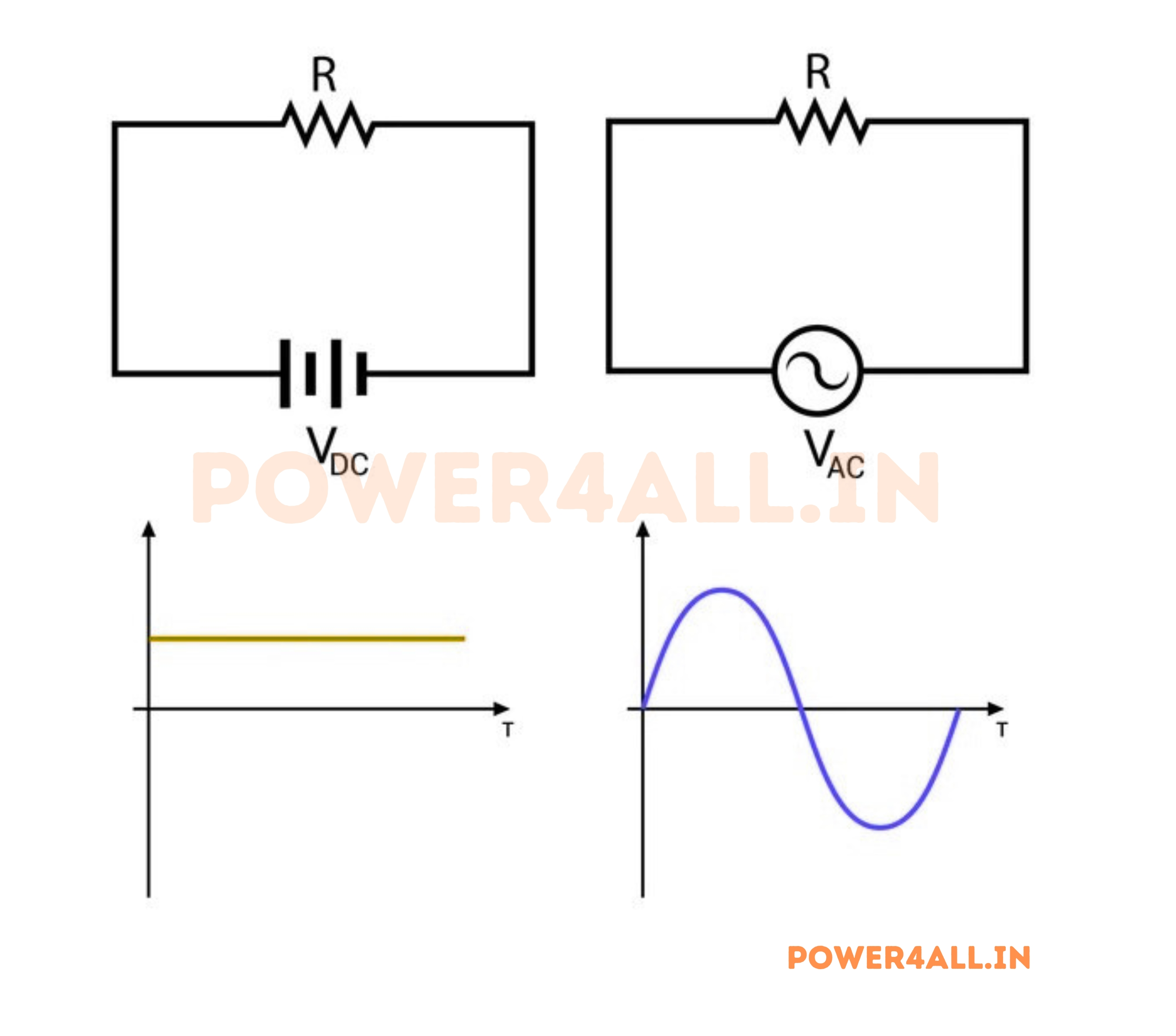
DC Current Flow
In DC circuits, charge carriers flow in one direction continuously. The drift velocity remains constant (for constant voltage and resistance), and the current direction never changes.
AC Current Flow
In AC circuits, charge carriers oscillate back and forth. They don't travel long distances but transfer energy through coordinated motion along the entire circuit length.
DC Characteristics
- Direction: Constant, unidirectional
- Magnitude: Can be constant or varying
- Energy transfer: Continuous in one direction
- Typical sources: Batteries, DC power supplies
AC Characteristics
- Direction: Alternates periodically
- Magnitude: Varies sinusoidally (typically)
- Energy transfer: Net energy flow despite alternating current
- Typical sources: Generators, transformers
AC Current in Power Systems
60Hz AC power system:
- Frequency: 60 complete cycles per second
- Period: 16.67 milliseconds per cycle
- Direction changes: 120 times per second
- Electron motion: Oscillates over tiny distances (~0.1 mm)
- Power delivery: Continuous despite oscillating current
Types of Current: Understanding Different Flow Patterns
Current comes in various forms, each with unique characteristics and applications. Understanding these different types helps in selecting appropriate circuit designs and analyzing system behavior under different conditions.
Direct Current (DC)
Pure DC Current
Characteristics: Constant magnitude and direction
- Stability: Current level remains constant over time
- Direction: Always flows in same direction
- Waveform: Horizontal line on oscilloscope
- Power calculation: P = V × I (simple multiplication)
Common DC Sources
- Batteries (chemical energy conversion)
- DC power supplies (regulated output)
- Solar panels (photovoltaic conversion)
- DC generators (mechanical to electrical)
Pulsating DC Current
Characteristics: Varying magnitude but constant direction
- Ripple: Small AC component on DC baseline
- Smoothing: Capacitors and inductors reduce ripple
- Quality factor: Measured by ripple percentage
- Applications: Rectified AC, switching power supplies
Ripple Current Sources
- Rectified AC power supplies
- Switching regulators (PWM output)
- Battery chargers
- Variable speed motor drives
Alternating Current (AC)
AC Current Fundamentals and Analysis
AC current continuously changes both magnitude and direction, following a sinusoidal pattern in most power systems. Understanding AC current parameters is crucial for power system analysis.
Key AC Current Parameters
| Parameter | Definition | Mathematical Expression | Practical Importance | Measurement |
|---|---|---|---|---|
| Peak Current (Ip) | Maximum instantaneous current | Ip = √2 × Irms | Component current rating | Oscilloscope measurement |
| RMS Current (Irms) | Effective current (heating equivalent) | Irms = Ip / √2 | Power calculations | Standard AC ammeter reading |
| Peak-to-Peak (Ipp) | Total current swing | Ipp = 2 × Ip | Circuit analysis | Oscilloscope peak-to-peak mode |
| Average Current | DC component | Iavg = 0 (pure AC) | Transformer design | DC-coupled measurement |
| Form Factor | Irms / Iavg | 1.11 (sine wave) | Waveform analysis | Calculated from measurements |
i(t) = Ip × sin(2πft + φ)
Instantaneous AC current as function of time
AC Current Advantages in Power Systems
Easy Transformation
Transformers can easily change AC current (and voltage) levels for efficient transmission and distribution.
Motor Operation
AC motors are simpler, more reliable, and easier to control than DC motors for many applications.
Circuit Protection
AC current naturally crosses zero twice per cycle, making it easier to interrupt during fault conditions.
AC Current Example
Household AC current: 60Hz, 15A RMS circuit
- Peak current: Ip = 15A × √2 = 21.2A
- Peak-to-peak: Ipp = 2 × 21.2A = 42.4A
- Period: T = 1/60Hz = 16.67ms
- Zero crossings: 120 times per second
- Power (resistive load): P = V × I = 120V × 15A = 1800W
Specialized Current Types
Pulsed Current
Characteristics: Short-duration current pulses
- Pulse width: Duration of current pulse
- Duty cycle: Percentage of time current flows
- Repetition rate: Frequency of pulse occurrence
- Applications: Digital circuits, motor control, welding
Pulse Current Applications
- Digital communication systems
- Radar and sonar transmitters
- Pulsed laser systems
- Medical defibrillators
Distorted AC Current
Characteristics: Non-sinusoidal AC waveforms
- Harmonics: Multiple frequency components
- THD: Total harmonic distortion measurement
- Causes: Nonlinear loads, switching circuits
- Effects: Heating, interference, power quality issues
Common Distortion Sources
- Switch-mode power supplies
- Variable frequency drives
- Electronic ballasts
- Computer equipment
Random/Noise Current
Characteristics: Unpredictable current variations
- Thermal noise: Johnson-Nyquist noise in resistors
- Shot noise: Discrete charge carrier effects
- Flicker noise: 1/f noise in semiconductors
- Measurement: Statistical analysis required
Noise Current Sources
- Thermal agitation in conductors
- Quantum effects in semiconductors
- Environmental electromagnetic interference
- Digital switching transients
Current Quality and Harmonics
Understanding Current Distortion and Quality Issues
Current quality affects system efficiency, equipment lifetime, and electromagnetic compatibility. Understanding and managing current distortion is crucial in modern electrical systems.
Total Harmonic Distortion (THD)
THD = √(I₂² + I₃² + I₄² + ...) / I₁
THD calculation for current harmonics
| Load Type | Typical Current THD | Dominant Harmonics | Effects | Mitigation |
|---|---|---|---|---|
| Resistive heating | < 5% | None (pure sine wave) | Minimal | Not required |
| Single-phase rectifier | 80-120% | 3rd, 5th, 7th | Neutral current, heating | Input filters, PFC circuits |
| Three-phase rectifier | 25-35% | 5th, 7th, 11th, 13th | Transformer heating | 12-pulse rectifiers, filters |
| Variable frequency drives | 30-50% | 5th, 7th, 11th, 13th | Motor heating, EMI | Line reactors, active filters |
| LED lighting | 10-30% | 3rd, 5th, 7th | Neutral current | High-quality drivers |
Harmonic Current Effects
High harmonic content in current can cause:
- Transformer overheating: Additional losses in windings and core
- Neutral conductor overloading: 3rd harmonic currents add in neutral
- Capacitor bank failures: Harmonic amplification and overheating
- Electronic equipment malfunction: Interference and power supply stress
Current Sources: Generation and Control
Current sources provide controlled current flow to circuits, independent of load variations. Understanding different types of current sources and their characteristics is essential for circuit design, testing, and specialized applications.
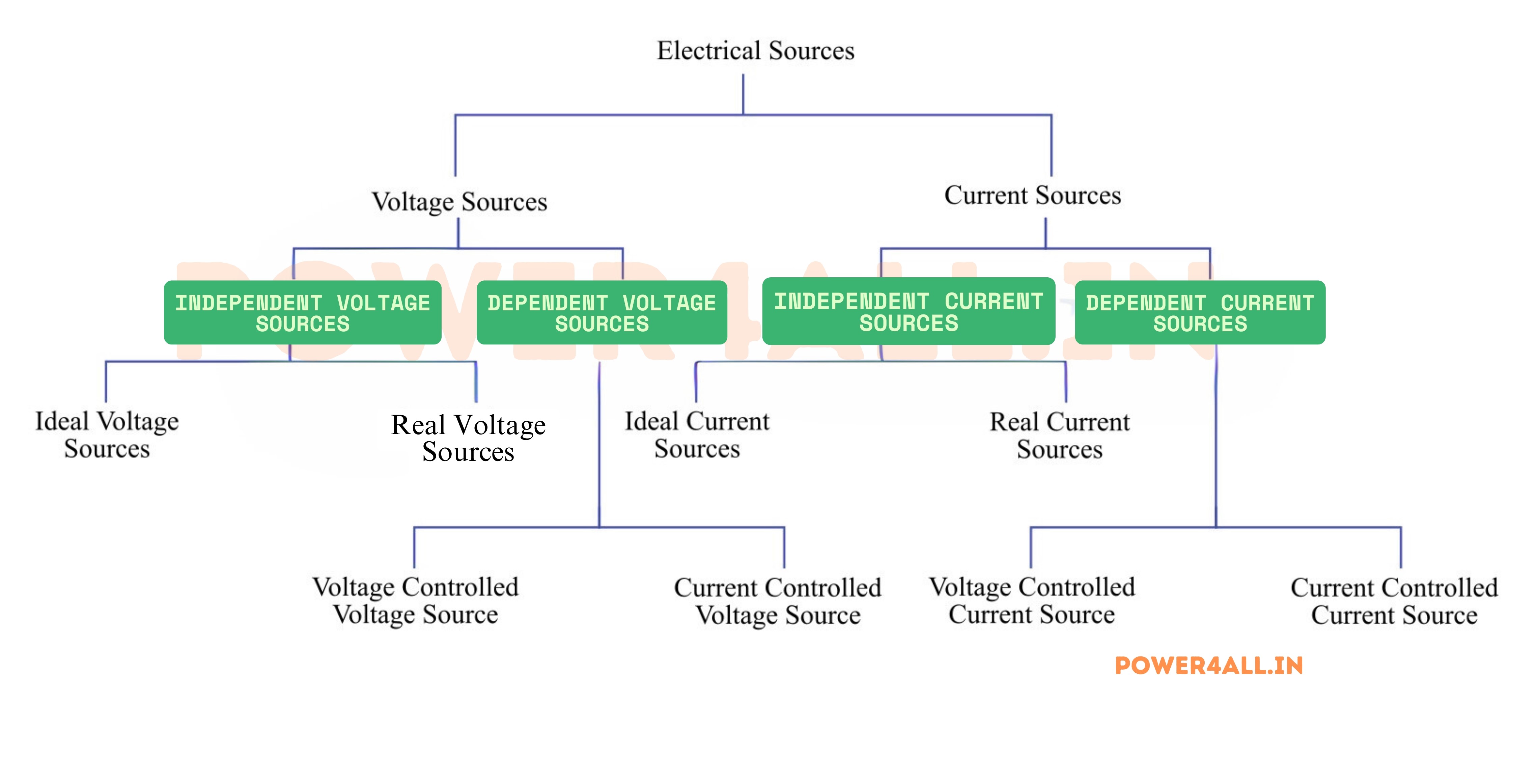
Ideal vs Real Current Sources
Ideal Current Source
Theoretical characteristics for circuit analysis
- Output current: Constant regardless of load
- Output resistance: Infinite (open circuit)
- Voltage compliance: Can provide any voltage needed
- Power delivery: Unlimited power capability
- Real-world equivalent: Does not exist physically
Circuit Analysis Applications
- Norton equivalent circuits
- Small-signal transistor models
- Operational amplifier analysis
- Filter design calculations
Real Current Source
Practical current sources with limitations
- Output resistance: Finite, typically high
- Compliance voltage: Limited output voltage range
- Current regulation: Good but not perfect
- Power limitation: Maximum power rating
- Temperature drift: Current varies with temperature
Performance Specifications
- Output impedance (typically >1MΩ)
- Current regulation (typically 0.1-1%)
- Compliance voltage range
- Temperature coefficient
Electronic Current Sources
Transistor-Based and Integrated Current Sources
Simple Transistor Current Sources
BJT Current Source
Basic transistor current source circuit
- Configuration: Common-emitter with base bias
- Current equation: Ic ≈ (Vb - Vbe) / Re
- Temperature sensitivity: -2mV/°C for Vbe
- Accuracy: ±5-10% without compensation
Improved Versions
- Wilson current mirror (better accuracy)
- Widlar current source (low currents)
- Cascode current source (high output impedance)
MOSFET Current Source
Field-effect transistor current sources
- Configuration: Common-source with gate bias
- Current equation: Id = K(Vgs - Vth)²
- Advantages: High input impedance, low noise
- Temperature effects: Threshold voltage varies
MOSFET Advantages
- Very high input impedance
- Low temperature coefficient (with compensation)
- Wide compliance voltage range
- Good for low-power applications
Precision Current Sources
| Type | Current Range | Accuracy | Temperature Coefficient | Applications |
|---|---|---|---|---|
| Voltage Reference + Op-amp | 1μA - 100mA | 0.1-1% | 10-50 ppm/°C | Sensor biasing, LED drivers |
| Integrated Current Source IC | 10μA - 10mA | 0.5-2% | 20-100 ppm/°C | Instrumentation, test equipment |
| Current Mirror Arrays | 1μA - 1mA | 1-5% | 50-200 ppm/°C | Analog ICs, bias circuits |
| Programmable Current Source | 1nA - 1A | 0.01-0.1% | 5-20 ppm/°C | Laboratory instruments |
LED Current Source Design
20mA LED driver using LM317:
- Reference voltage: 1.25V between ADJ and OUT
- Sense resistor: R = 1.25V / 20mA = 62.5Ω
- Standard value: 62Ω (closest standard resistor)
- Actual current: I = 1.25V / 62Ω = 20.2mA
- Power dissipation: P = I²R = 25mW in resistor
Specialized Current Sources
Constant Current Diodes (CCDs)
Two-terminal current regulating devices
- Structure: Junction FET with gate tied to source
- Current range: Typically 0.2mA to 10mA
- Voltage range: 1V to hundreds of volts
- Tolerance: ±10% to ±20% typical
- Applications: LED biasing, simple current limiting
CCD Advantages
- Two-terminal simplicity
- No external components required
- Good temperature stability
- Low cost for simple applications
Current Limiting Circuits
Protection-oriented current sources
- Foldback limiting: Current decreases under overload
- Constant current limiting: Fixed maximum current
- Thermal limiting: Temperature-dependent limiting
- Electronic fuses: Resettable current protection
Protection Applications
- Power supply short-circuit protection
- Motor start current limiting
- Battery charging current control
- LED array current regulation
Switching Current Sources
High-efficiency current regulation
- Buck current regulator: Step-down current control
- Boost current regulator: Step-up current control
- PWM control: Average current regulation
- Efficiency: 80-95% typical
Switching Advantages
- High efficiency (low heat generation)
- Wide input voltage range
- Precise current control
- Suitable for high-power applications
Current Source Selection Criteria
Accuracy Requirements
Consider initial accuracy, temperature coefficient, and long-term stability. Precision applications may require 0.01% accuracy with temperature compensation.
Current Range and Compliance
Ensure the source can provide required current range with adequate compliance voltage for the intended load variations.
Dynamic Response
Fast current settling may be required for switching applications, while slow thermal drift is more important for bias circuits.
Cost vs Performance
Balance precision requirements with cost. Simple resistor-based sources may suffice for non-critical applications.
Measuring Current: Tools and Techniques
Accurate current measurement is fundamental to electrical testing, circuit analysis, and system troubleshooting. Understanding measurement tools, techniques, and potential pitfalls ensures reliable results and safe practices.
Current Measurement Fundamentals
Critical Difference from Voltage Measurement
Current must be measured in series with the circuit, requiring the circuit to be opened or using indirect methods. This fundamental difference makes current measurement more challenging and potentially disruptive than voltage measurement.
Direct Current Measurement Methods
Digital Multimeters (DMM)
Most common current measurement tool
DMM Current Measurement Features
- Multiple ranges: μA, mA, A scales
- Auto-ranging: Automatic scale selection
- True RMS: Accurate AC current measurement
- Min/Max recording: Capture peak currents
- Data logging: Record current over time
DMM Current Limitations
- Circuit interruption: Must break circuit to insert meter
- Voltage drop: Internal shunt resistance affects circuit
- Fuse protection: Can blow fuse if range exceeded
- Frequency response: Limited AC frequency range
- Safety considerations: High current can damage meter
DMM Current Measurement Procedure
- Turn off power to the circuit being measured
- Select current function and appropriate range on DMM
- Break the circuit at the point where current is to be measured
- Connect DMM in series with the circuit (red lead to positive current flow)
- Turn on power and read the current value
- Turn off power before removing meter
Oscilloscope Current Probes
Non-intrusive current measurement for dynamic signals
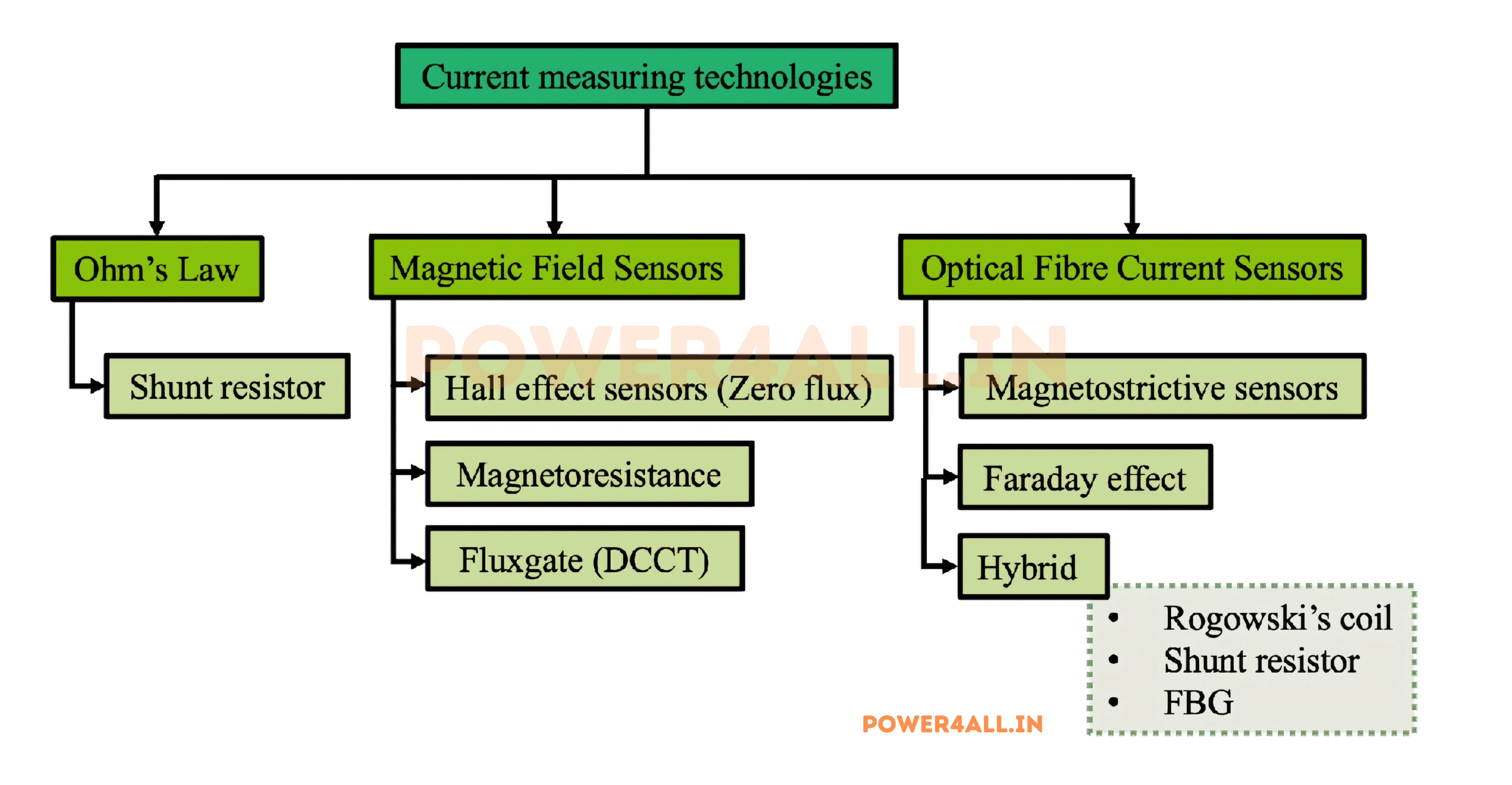
Current Probe Types
- Hall effect probes: DC to several MHz bandwidth
- Rogowski coils: AC only, very wide bandwidth
- Transformer probes: AC only, high sensitivity
- Shunt-based probes: Requires circuit interruption
Advantages of Current Probes
- Non-intrusive: No circuit interruption required
- Wide bandwidth: DC to GHz for some types
- High sensitivity: Can measure mA to kA ranges
- Safety: Isolated measurement reduces shock risk
- Waveform analysis: View current vs. time
Current Probe Specifications
Typical Hall effect current probe:
- Current range: 1mA to 30A
- Bandwidth: DC to 2MHz
- Accuracy: ±1% of reading
- Resolution: 1mA at lowest range
- Safety rating: CAT III 600V
Indirect Current Measurement Techniques
Non-Intrusive Current Measurement Methods
Clamp-On Current Meters
Clamp meters measure current by detecting the magnetic field around a current-carrying conductor. They provide convenient, non-intrusive measurements ideal for field work.
AC Clamp Meters
- Principle: Transformer operation (AC only)
- Frequency range: 50Hz to 1kHz typical
- Accuracy: ±2% to ±5%
- Current range: 1A to 1000A typical
- Advantages: Simple, no power required
Hall Effect Clamp Meters
- Principle: Hall effect sensor
- Current types: Both AC and DC
- Accuracy: ±1% to ±3%
- Current range: 1mA to 3000A
- Power required: Battery operated
Shunt Resistor Method
Using a precision shunt resistor to convert current to voltage for measurement. This method is accurate but requires circuit modification.
I = V_shunt / R_shunt
Current equals voltage drop across shunt divided by shunt resistance
| Shunt Type | Current Range | Accuracy | Power Rating | Applications |
|---|---|---|---|---|
| Manganin shunt | 1A - 10kA | 0.1% - 0.5% | 1W - 1000W | DC power systems, battery monitoring |
| Current sense resistor | 1mA - 10A | 1% - 5% | 0.1W - 5W | Electronic circuits, current limiting |
| PCB trace shunt | 100mA - 1A | 5% - 10% | 0.1W - 1W | Low-cost current sensing |
Shunt Resistor Calculation
Design 10A shunt for 100mV full scale:
- Required resistance: R = V/I = 100mV/10A = 10mΩ
- Power dissipation: P = I²R = 10²×0.01 = 1W
- Recommended rating: 2W shunt for safety margin
- Material choice: Manganin for temperature stability
- Connection: 4-wire (Kelvin) connection for accuracy
Current Measurement Safety
Critical Safety Warnings
- Never exceed meter ratings: High current can destroy meters and create fire hazards
- Check fuse condition: Blown current fuses can cause dangerous situations
- Use appropriate probe ratings: Ensure probes are rated for the circuit voltage
- Be aware of arc flash: Opening circuits under load can create dangerous arcs
- Use proper PPE: Arc-rated clothing for high-energy circuits
Common Measurement Errors and Solutions
| Error Type | Cause | Effect | Solution | Prevention |
|---|---|---|---|---|
| Circuit Loading | Meter internal resistance | Reduced current reading | Use lower resistance meter | Check meter burden voltage |
| Thermoelectric EMF | Dissimilar metal junctions | DC offset in measurements | Use copper connections | Minimize temperature differences |
| Magnetic Coupling | External magnetic fields | False readings in clamp meters | Shield measurement area | Keep away from magnetic sources |
| Frequency Response | Limited meter bandwidth | Incorrect AC measurements | Use appropriate bandwidth meter | Check specifications vs signal |
Current in Circuits: Analysis and Behavior
Understanding how current behaves in different circuit configurations is essential for circuit analysis, design, and troubleshooting. Current flow follows specific laws that govern all electrical circuits and enable predictable system behavior.
Kirchhoff's Current Law (KCL)
∑I_in = ∑I_out
Current flowing into a node equals current flowing out
Understanding KCL
Physical Basis of KCL
KCL is based on conservation of electric charge. Charge cannot accumulate at any point in a circuit under steady-state conditions, so all current flowing into a junction must equal the current flowing out.
Simple KCL Example
Three-branch junction:
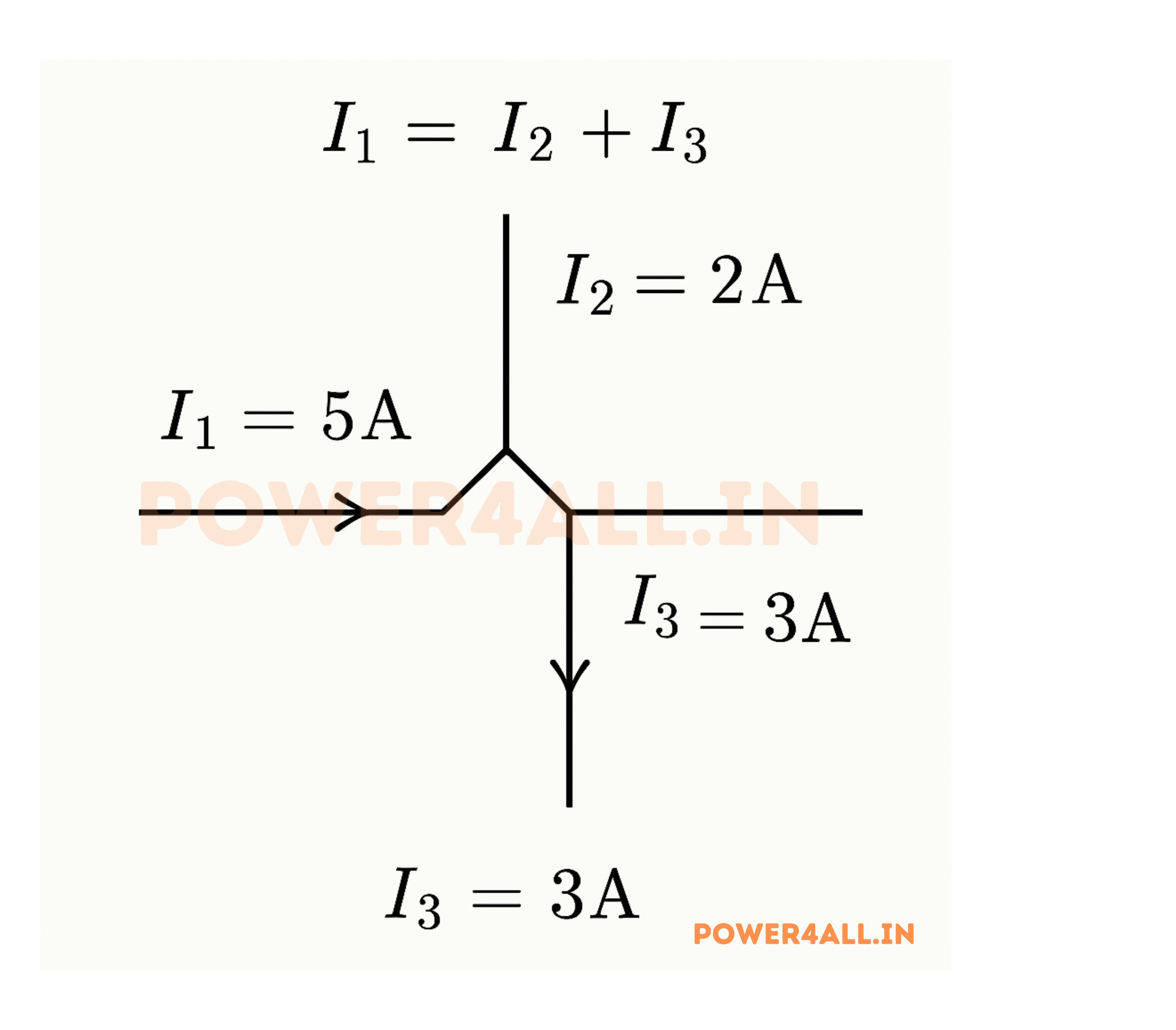
- Current in: I₁ = 5A
- Currents out: I₂ = 2A, I₃ = ?
- KCL equation: I₁ = I₂ + I₃
- Solution: 5A = 2A + I₃
- Result: I₃ = 3A
Series Circuits: Same Current Everywhere
Current Flow in Series Circuits
In series circuits, current is the same through all components because there's only one path for current flow. This fundamental principle enables many circuit analysis techniques.
Series Circuit Characteristics
Identical Current
All components carry the same current because charge flow rate must be constant throughout a single path.
Resistance Addition
Total resistance equals sum of individual resistances: R_total = R₁ + R₂ + R₃ + ...
Voltage Division
Voltage divides proportionally among resistances, but current remains constant throughout.
Single Failure Point
If one component fails open, current stops flowing through entire circuit.
Series Circuit Current Calculation
Circuit: 12V battery with 100Ω, 200Ω, and 300Ω resistors in series
- Total resistance: R_total = 100Ω + 200Ω + 300Ω = 600Ω
- Circuit current: I = V/R = 12V/600Ω = 0.02A = 20mA
- Current through each resistor: 20mA (same everywhere)
- Power dissipation: P₁ = I²R₁ = (0.02)²×100 = 0.04W
- Verification: Total power = V×I = 12V×0.02A = 0.24W
Series Circuit Applications
Current Limiting
Series resistors limit current to sensitive components like LEDs
- LED protection: Prevents overcurrent damage
- Calculation: R = (V_supply - V_LED) / I_desired
- Power rating: Must handle I²R dissipation
Current Sensing
Small series resistors (shunts) enable current measurement
- Shunt resistors: Very low resistance, high precision
- Voltage measurement: V = I × R_shunt
- Amplification: Op-amps amplify small voltages
Parallel Circuits: Current Division
Current Distribution in Parallel Circuits
In parallel circuits, current divides among branches inversely proportional to their resistances. This principle enables load sharing and redundant circuit paths.
Current Divider Formula
I₁ = I_total × (R₂ / (R₁ + R₂))
Current through R₁ in a two-resistor current divider
Parallel Circuit Characteristics
Equal Voltages
All parallel branches have identical voltage across them
- Same potential difference: Each branch sees full supply voltage
- Independent operation: Each branch operates independently
- No voltage division: Unlike series circuits
Current Division
Total current splits among branches based on resistance
- Lower resistance: Draws more current (easier path)
- Higher resistance: Draws less current
- Current calculation: I = V/R for each branch
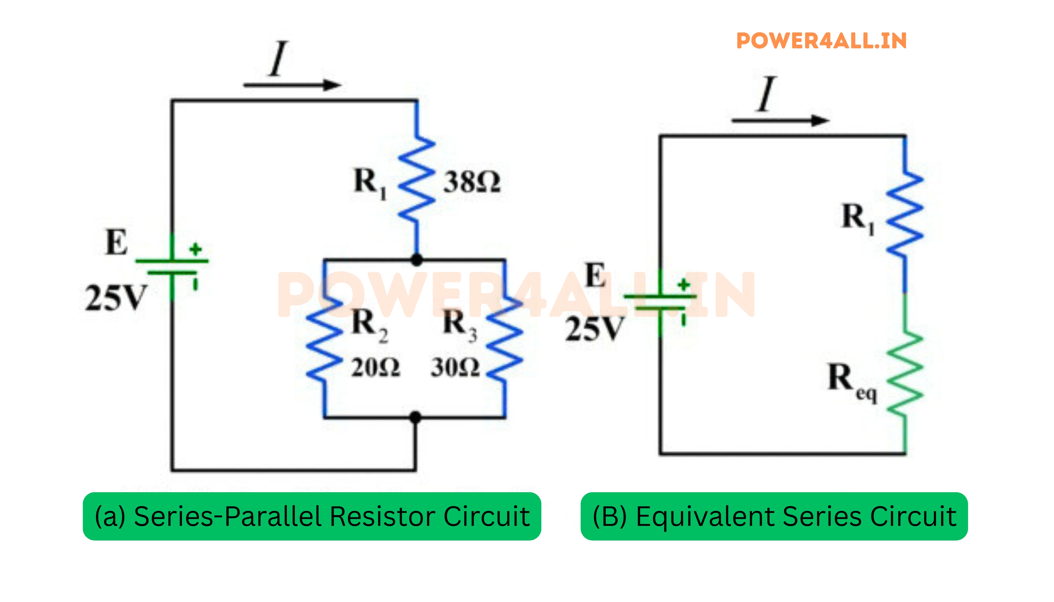
Parallel Circuit Current Example
12V supply with 6Ω and 12Ω resistors in parallel:
- Branch currents: I₁ = 12V/6Ω = 2A, I₂ = 12V/12Ω = 1A
- Total current: I_total = I₁ + I₂ = 2A + 1A = 3A
- Total resistance: 1/R_total = 1/6Ω + 1/12Ω = 1/4Ω, so R_total = 4Ω
- Verification: I_total = V/R_total = 12V/4Ω = 3A ✓
- Current division: Lower resistance (6Ω) carries more current (2A)
Practical Applications of Current Division
Household Wiring
All outlets and lights are parallel branches, allowing independent operation and current sharing based on load requirements.
Battery Parallel Connection
Parallel batteries share load current, extending runtime. Current division depends on internal resistances and charge states.
Current Sharing in Power Supplies
Parallel power supplies must share load current equally. Current sharing circuits prevent one supply from carrying all the load.
Complex Circuit Analysis
Node Analysis Method
Systematic approach using KCL at each node
- Step 1: Identify all nodes in the circuit
- Step 2: Choose reference node (ground)
- Step 3: Write KCL equation for each node
- Step 4: Solve simultaneous equations
- Advantage: Works for any circuit topology
Mesh Analysis Method
Loop-based approach using KVL
- Step 1: Identify independent loops
- Step 2: Assign loop currents
- Step 3: Write KVL equation for each loop
- Step 4: Solve for loop currents
- Best for: Circuits with many series elements
Common Current Levels: Understanding Applications
Current levels vary enormously across different applications, from nanoamperes in precision electronics to megaamperes in industrial processes. Understanding typical current ranges helps with component selection, safety planning, and system design.
Current Level Classifications
| Current Range | Classification | Typical Applications | Measurement Tools | Safety Level | Special Considerations |
|---|---|---|---|---|---|
| 1pA - 1μA | Ultra-low current | Ion chambers, precision sensors | Electrometers, picoammeters | Safe to touch | Require shielding from noise |
| 1μA - 1mA | Low current | Microcontrollers, sensors, timing circuits | Precision DMMs, microammeters | Safe to touch | Battery-powered devices |
| 1mA - 100mA | Small signal current | LEDs, small circuits, indicators | Standard DMMs, milliammeters | Safe to touch | Typical electronic circuits |
| 100mA - 10A | Medium current | Household appliances, small motors | Standard ammeters, clamp meters | Can cause shock | Circuit breaker protection |
| 10A - 1kA | High current | Large motors, heating, welding | Clamp meters, current transformers | Dangerous | Arc flash hazards |
| > 1kA | Very high current | Power transmission, large industry | Current transformers, Rogowski coils | Lethal | Specialized safety equipment |
Electronics and Digital Systems
Microelectronics Current Levels
Digital Logic Current Consumption
- CMOS static current: 1nA - 10μA (sleep mode)
- CMOS active current: 1mA - 100mA (operating)
- TTL logic: 1mA - 20mA per gate
- Modern processors: 1W - 150W (at operating voltage)
Memory and Storage
- SRAM standby: 1μA - 10μA
- DRAM refresh: 10mA - 100mA
- Flash memory write: 20mA - 100mA
- SSD operation: 1W - 5W
Smartphone Current Profile
- Sleep mode: 1-5mA (mostly baseband)
- Idle with screen off: 10-30mA
- Normal operation: 100-500mA
- Gaming/video: 1-2A
- Camera/GPS/WiFi: Additional 100-300mA each
Lighting Applications
LED Lighting Current Levels
- Indicator LEDs: 2mA - 20mA
- High-brightness LEDs: 350mA - 1A
- LED strips: 1A - 5A per meter
- LED floodlights: 1A - 10A
Traditional Lighting
- Incandescent 60W: 0.5A (120V system)
- Fluorescent 32W: 0.27A (with ballast)
- HID 400W: 4.6A (including ballast)
- Street lighting: 1A - 10A per fixture
LED vs Incandescent Comparison
Same light output (800 lumens):
- 60W incandescent: 0.5A at 120V
- 10W LED: 0.083A at 120V
- Current reduction: 83% less current
- Heat generation: 85% less heat
Sensor and Instrumentation
Sensor Current Requirements
- Passive sensors: 0A (resistance/capacitance change)
- Active sensors: 1mA - 10mA supply current
- 4-20mA loops: Industrial standard current levels
- Temperature sensors: 1μA - 1mA
Instrumentation Current Loops
- 4mA: 0% measurement (alive signal)
- 12mA: 50% of measurement range
- 20mA: 100% measurement (full scale)
- Advantages: Noise immunity, long distance capability
Power Systems and Industrial Applications
Industrial and Power System Current Levels
Household and Commercial Currents
| Appliance/Load | Typical Current (120V) | Typical Current (240V) | Circuit Protection | Wire Size |
|---|---|---|---|---|
| LED lights | 0.1A - 1A | 0.05A - 0.5A | 15A breaker | 14 AWG |
| Microwave oven | 12A - 15A | 6A - 7.5A | 20A breaker | 12 AWG |
| Electric water heater | N/A | 20A - 25A | 30A breaker | 10 AWG |
| Central AC unit | N/A | 15A - 50A | 60A breaker | 6 AWG |
| Electric vehicle charger | N/A | 32A - 80A | 100A breaker | 4 AWG |
Industrial Motor Current Levels
Motor Starting vs Running Current
- Starting current: 6-8× normal running current
- Running current: Nameplate current at full load
- No-load current: 20-40% of full load current
- Locked rotor current: Maximum possible current
Motor Current Examples
- 1 HP motor (480V): 1.4A running, 8.4A starting
- 10 HP motor (480V): 14A running, 84A starting
- 100 HP motor (480V): 124A running, 744A starting
- 1000 HP motor (4160V): 134A running, 804A starting
Industrial Plant Current Distribution
Typical manufacturing facility:
- Main service: 2000A at 4160V (13.8MW capacity)
- Large motors: 100A - 500A each
- Process heating: 200A - 1000A
- Lighting/outlets: 100A - 300A total
- HVAC systems: 50A - 200A each
- Control systems: 10A - 50A total
Specialized High-Current Applications
Welding Applications
Arc welding: 50A-500A, Spot welding: 1kA-50kA, Specialized welding processes can exceed 100kA for brief periods.
Electrochemical Processes
Aluminum smelting: 100kA-500kA per pot, Electroplating: 1A-1000A, Battery formation: 10A-1000A depending on size.
Electromagnetic Applications
MRI magnets: 100A-1000A continuous, Particle accelerators: 1kA-10kA, Fusion research: 10kA-1MA briefly.
Transportation Systems
Electric vehicle motors: 100A-400A, Electric trains: 1kA-5kA, Ship propulsion: 1kA-10kA.
Current Level Selection Guidelines
When designing circuits or selecting components:
- Start with load requirements: Determine actual current needs first
- Add safety margins: 25% margin for continuous loads, 125% for motor loads
- Consider startup currents: Motors and capacitive loads have high inrush
- Account for temperature: Current-carrying capacity decreases with temperature
- Plan for growth: Leave room for future expansion in current capacity
Current Safety: Critical Protection Measures
Electric current is what actually causes injury and death in electrical accidents. Understanding current effects on the human body, safety procedures, and protection methods is essential for anyone working with electrical systems. Current safety cannot be compromised - lives depend on it.
Critical Safety Truth
Current kills, not voltage. While voltage determines whether current can flow through body resistance, it's the actual current through vital organs that causes injury. Even low voltages can be lethal under the right (wrong) conditions.
Current Effects on the Human Body
| Current Level (AC, 60Hz) | Physical Effect | Duration Tolerance | Typical Cause | Safety Action Required |
|---|---|---|---|---|
| < 1mA | No sensation | Indefinite | Normal leakage currents | None - safe level |
| 1-5mA | Slight tingling sensation | Indefinite | Wet skin contact, minor faults | Investigate source |
| 5-10mA | Painful shock, muscular control maintained | Indefinite | Faulty appliances, GFCI trip level | Immediate disconnection needed |
| 10-20mA | Muscular control lost, "can't let go" | Minutes | Direct contact with live conductors | Emergency assistance required |
| 50-100mA | Ventricular fibrillation possible | Seconds | Electrical shock accidents | Immediate medical attention |
| 100-200mA | Certain ventricular fibrillation | Instant | Severe electrical accidents | Usually fatal without immediate CPR |
| > 200mA | Severe burns, cardiac arrest | Instant | High-voltage exposure | Massive tissue damage, often fatal |
Factors Affecting Current Through Human Body
Human Body Resistance
Variable resistance affects current flow
Typical Body Resistance Values
- Dry skin, hand-to-hand: 10kΩ - 100kΩ
- Wet skin, hand-to-hand: 1kΩ - 5kΩ
- Internal body (no skin): 300Ω - 500Ω
- Hand-to-foot (through heart): 500Ω - 1.5kΩ (wet)
Current Calculation Examples
120V contact, wet conditions:
- Body resistance: 1200Ω (wet skin)
- Current: I = 120V / 1200Ω = 100mA
- Result: Potentially lethal current level
Same voltage, dry conditions:
- Body resistance: 50kΩ (dry skin)
- Current: I = 120V / 50kΩ = 2.4mA
- Result: Painful but not immediately dangerous
Environmental Factors
Conditions that affect current flow and safety
Risk-Increasing Factors
- Moisture: Dramatically reduces skin resistance
- Salt/sweat: Makes skin more conductive
- Cuts/abrasions: Bypass high skin resistance
- Metal jewelry: Creates additional current paths
- Grounded surfaces: Provides return current path
Frequency Effects
- DC current: 2-4× more dangerous than AC for same level
- 60Hz AC: Most dangerous frequency for heart
- High frequency (>10kHz): Less dangerous, causes burns
- Very high frequency: Current stays on skin surface
Current Protection Devices
Devices That Protect Against Dangerous Currents
Ground Fault Circuit Interrupters (GFCI)
GFCI Operation
Detects current imbalance indicating ground fault
- Trip threshold: 4-6mA current difference
- Response time: 25 milliseconds maximum
- Protection principle: Current in must equal current out
- Types: Outlet, circuit breaker, portable
GFCI Applications
Required locations for GFCI protection
- Bathrooms: All outlets within 6 feet of sink
- Kitchens: Countertop outlets within 6 feet of sink
- Outdoor outlets: All 120V, 15A and 20A outlets
- Garages: All outlets except those for appliances
- Basements: Unfinished areas and workshop outlets
Circuit Breakers and Fuses
While primarily designed for overcurrent protection, these devices also provide some personal protection by limiting the duration of fault currents.
| Protection Device | Trip/Blow Threshold | Response Time | Personal Protection | Equipment Protection |
|---|---|---|---|---|
| Standard Circuit Breaker | 125% of rating (sustained) | Minutes to hours | Limited (high currents only) | Excellent for overloads |
| Fast-Acting Fuse | 200% of rating | Seconds to minutes | Better than standard breakers | Good for overcurrent |
| GFCI Breaker | 5mA ground fault | 25 milliseconds | Excellent for ground faults | Normal overcurrent protection |
| Arc Fault Breaker | Arc fault signatures | Milliseconds | Prevents arc-related fires | Protects against arc damage |
Important Limitation
Standard circuit breakers and fuses are NOT designed to protect people from electrocution. A 15A breaker allows 15,000mA of current - 150 times the lethal level. Personal protection requires GFCI devices or other specialized equipment.
Safe Work Practices for Current Protection
Procedures to Prevent Dangerous Current Exposure
Lockout/Tagout (LOTO) for Current Control
The most effective way to prevent dangerous current exposure is to eliminate the current source entirely through proper LOTO procedures.
Live Work Safety (When LOTO Impossible)
Qualified Personnel Only
Only trained, qualified electrical workers should perform live work. Qualification includes understanding current hazards and using appropriate safety procedures.
Appropriate PPE
Arc-rated clothing, insulated gloves, safety glasses, and hard hats. PPE must be rated for the incident energy level present.
Insulated Tools
Use properly rated insulated tools. Test tools before each use and inspect for damage that could allow current flow.
Buddy System
Never work alone on live circuits. Have a qualified observer ready to provide emergency assistance if needed.
Arc Flash Incident Energy Calculation
480V panel, 25kA available fault current:
- Working distance: 18 inches
- Clearing time: 0.1 seconds (fast breaker)
- Calculated incident energy: 8 cal/cm²
- Required PPE: Category 2 (8 cal/cm² arc-rated suit)
- Alternative: Use remote racking or longer tools
Emergency Response to Current Accidents
Electrical Shock Emergency Response
Current Safety in Different Environments
Wet Environments
- Extra hazard: Water reduces body resistance dramatically
- Required protection: GFCI on all circuits
- Equipment: Must be rated for wet locations
- Work practices: De-energize before any maintenance
Industrial Settings
- Higher voltages: Greater potential for dangerous currents
- Arc flash hazards: High available fault currents
- Training requirements: Qualified electrical workers only
- Safety systems: Comprehensive electrical safety programs
Practical Applications: Current in Real-World Systems
Electric current enables virtually every aspect of modern technology. Understanding how current is used, controlled, and managed in real-world applications provides insight into the fundamental role of current in our technological society.
Electric Motors and Motion Control
Motor Current Characteristics
Current vs Torque Relationship
In most motors, torque is directly proportional to current. This relationship enables precise control of mechanical output through current control.
T = k × I
Torque (T) equals motor constant (k) times current (I)
Motor Current Phases
- Starting current: 6-8× normal (locked rotor)
- Acceleration current: Decreases as speed increases
- Running current: Proportional to mechanical load
- No-load current: Covers friction and magnetic losses
Electric Vehicle Motor Example
Tesla Model S motor specifications:
- Peak current: ~1000A (brief acceleration)
- Continuous current: ~300A (highway cruising)
- Efficiency: >95% at optimal current levels
- Regenerative current: 200-400A during braking
- Control method: PWM current control at 10kHz
Variable Frequency Drives (VFDs)
Current Control Strategies
- V/f control: Maintains constant volts-per-hertz ratio
- Vector control: Independent control of torque and flux currents
- Direct torque control: Rapid torque response through current control
- Sensorless control: Estimates rotor position from current measurements
Current Measurement in VFDs
- Hall effect sensors: Measure instantaneous current
- Current transformers: For AC current measurement
- Shunt resistors: DC bus current measurement
- Digital filtering: Remove switching noise from measurements
Servo Motor Systems
Precision Current Control
- Current loops: Inner control loop (fastest response)
- Velocity loops: Middle control loop
- Position loops: Outer control loop (slowest)
- Feed-forward: Anticipatory current commands
Servo Current Characteristics
- Peak current: 3-5× continuous for acceleration
- Holding current: Maintains position against load
- Bandwidth: Current loop >1kHz for good performance
- Accuracy: ±1% current control typical
Power Electronics and Current Conversion
Current Control in Power Electronic Systems
Switching Power Supply Current Control
Modern power supplies use sophisticated current control techniques to achieve high efficiency and regulation.
Current Mode Control
- Peak current control: Controls peak inductor current
- Average current control: Controls average inductor current
- Hysteretic control: Current ripple band control
- Advantages: Fast response, inherent current limiting
Current Sensing Methods
- Shunt resistors: Direct current measurement
- Current transformers: AC current sensing
- Hall effect sensors: Non-invasive measurement
- DCR sensing: Use inductor resistance as current sense
LED Driver Current Control
Constant current LED driver design:
- Output current: 350mA ±3% regulation
- Input voltage range: 90-265V AC
- Current sensing: 0.1Ω shunt resistor
- Control IC: Peak current mode controller
- Switching frequency: 100kHz for small magnetics
- Efficiency: >85% over full load range
Battery Charging Current Control
| Charging Phase | Current Characteristic | Control Method | Typical Duration | Safety Considerations |
|---|---|---|---|---|
| Trickle/Pre-charge | Low constant current (C/10) | Current limiting circuit | 30-60 minutes | Detect deep discharge |
| Constant Current (CC) | High constant current (C/2 to 2C) | Switching current regulator | 1-3 hours | Temperature monitoring |
| Constant Voltage (CV) | Decreasing current | Voltage regulation, current tapers | 1-2 hours | Termination current detection |
| Maintenance | Very low current (C/100) | Voltage regulation | Continuous | Overcharge protection |
Communication and Signal Processing
Current Loop Communication
4-20mA Current Loops
Industrial standard for analog signal transmission over long distances with excellent noise immunity.
- 4mA: 0% of measurement range (live zero)
- 12mA: 50% of measurement range
- 20mA: 100% of measurement range (full scale)
- 0mA: Fault condition (broken wire detection)
Advantages of Current Loops
- Noise immunity: Current less affected by electrical noise
- Long distance: Can span kilometers without signal degradation
- Two-wire operation: Signal and power on same wires
- Intrinsic safety: Low energy levels safe in hazardous areas
Temperature Transmitter Example
0-100°C temperature measurement:
- 0°C: Output = 4mA
- 25°C: Output = 4 + (25/100)×16 = 8mA
- 50°C: Output = 4 + (50/100)×16 = 12mA
- 100°C: Output = 4 + (100/100)×16 = 20mA
- Wire break: Output = 0mA (fault detected)
RF and High-Frequency Current
Antenna Current Distribution
- Standing wave patterns: Current varies along antenna length
- Current nodes: Points of minimum current
- Current antinodes: Points of maximum current
- Radiation resistance: Effective resistance "seen" by transmitter
Transmission Line Currents
- Characteristic impedance: Z₀ = √(L/C)
- Forward current: Current traveling toward load
- Reflected current: Current reflected from mismatched load
- VSWR: Voltage Standing Wave Ratio indicates mismatch
Medical and Biological Applications
Current in Medical and Biological Systems
Therapeutic Current Applications
Cardiac Stimulation
- Pacemakers: 1-5mA pulses, 0.5ms duration
- Defibrillators: 5-20A, 5-10ms duration
- Cardioversion: 1-10A, synchronized with heart rhythm
- Safety: Current path and timing critical
Neural Stimulation
- Deep brain stimulation: 1-10mA, 60-180Hz
- Spinal cord stimulation: 0.1-10mA adjustable
- TENS units: 1-80mA, various frequencies
- Cochlear implants: 10-1000μA per electrode
Diagnostic Current Applications
| Diagnostic Method | Current Level | Frequency Range | Measurement Purpose | Safety Requirements |
|---|---|---|---|---|
| ECG/EKG | No applied current | 0.05-100Hz | Detect heart electrical activity | Patient safety critical |
| EEG | No applied current | 0.1-100Hz | Measure brain electrical activity | Non-invasive, low current |
| EMG | Microampere to milliampere | 10-500Hz | Muscle activity measurement | Safe, controlled current |
These diagnostic methods rely on extremely low or no applied current to ensure patient safety while providing critical physiological information.
Safety Precautions in Medical Current Applications
- Use of isolated power supplies and patient isolation transformers
- Strict adherence to medical electrical safety standards (IEC 60601)
- Regular equipment maintenance and calibration
- Training for medical personnel on electrical safety
Current Troubleshooting: Systematic Problem Solving
Effective current troubleshooting requires systematic methodology, proper tools, and understanding of common failure modes. This approach minimizes downtime and ensures safe, accurate diagnosis of electrical problems.
Troubleshooting Methodology
Common Current Problems and Solutions
| Problem Description | Likely Causes | Diagnostic Tests | Typical Solutions | Prevention |
|---|---|---|---|---|
| No Current | Open circuit, blown fuse, tripped breaker | Continuity test, visual inspection | Replace fuse, reset breaker, repair open | Proper circuit protection sizing |
| Low Current | High resistance connections, voltage drop | Current measurement under load | Tighten connections, upgrade conductors | Regular maintenance, load analysis |
| High Current | Short circuit, faulty regulator, overload | Current measurement, thermal imaging | Repair faults, replace components | Proper circuit design, protection devices |
| Current Fluctuations | Loose connections, varying loads | Monitor current over time | Secure connections, install stabilizers | Torque specifications, load balancing |
| Ground Faults | Insulation failure, moisture | Insulation resistance testing | Repair insulation, eliminate moisture | Environmental protection |
| Transient Currents | Switching operations, lightning | Oscilloscope capture, surge monitoring | Install surge suppressors | Proper grounding, surge protection |
Diagnostic Tools and Techniques
Digital Multimeters (DMM)
Key Capabilities
- DC current: Batteries, power supplies, control circuits
- AC current: Power systems, motor circuits
- True RMS: Accurate readings with distorted waveforms
- Min/Max recording: Capture intermittent problems
Measurement Best Practices
- Proper range selection: Start high, work down
- Series connection: Break circuit to insert meter
- Safety ratings: Use CAT III/IV for power systems
- Probe condition: Inspect for damage before use
Oscilloscopes with Current Probes
Advanced Diagnostics
- Waveform analysis: See current shape, not just RMS value
- Transient capture: Catch fast current spikes
- Harmonic analysis: FFT shows frequency content
- Power measurements: Real, reactive, apparent power
Current Probe Types
- Hall effect: DC and AC measurement capability
- Rogowski coils: Wide bandwidth, flexible
- Current transformers: High accuracy for AC
- Shunt-based: Precise but intrusive
Clamp Meters
Non-Intrusive Measurement
- AC clamp meters: Simple transformer operation
- Hall effect clamps: AC and DC capability
- High-current clamps: Up to several thousand amperes
- Precision clamps: mA level sensitivity
Measurement Limitations
- Single conductor: Must isolate one conductor
- Conductor position: Centered in clamp jaw
- External fields: Can affect readings
- Frequency response: Limited at high frequencies
Advanced Troubleshooting Techniques
Power Quality and Harmonic Analysis
Current Signature Analysis
Analyzing current waveforms can reveal equipment problems before they cause failures.
| Current Signature | Possible Cause | Equipment Type | Diagnostic Action | Corrective Measure |
|---|---|---|---|---|
| High 3rd harmonic | Single-phase loads on 3-phase system | Office equipment, lighting | Harmonic analysis | Load balancing, harmonic filters |
| Excessive 5th/7th harmonics | Variable frequency drives | Motor drives, power supplies | Drive parameters check | Line reactors, active filters |
| Current spikes | Switching transients | Contactors, motors | Oscilloscope capture | Surge suppressors, soft starters |
| Gradually increasing current | Bearing wear, misalignment | Motors, pumps | Vibration analysis, thermal imaging | Mechanical maintenance |
Motor Current Signature Analysis (MCSA)
Technique for predictive maintenance:
- Baseline measurement: Record healthy motor current spectrum
- Periodic monitoring: Compare current signatures over time
- Fault identification: Specific frequency patterns indicate problems
- Trending analysis: Track fault progression
- Maintenance scheduling: Plan repairs before failures occur
Current Control: Regulation and Management
Controlling current is essential for protecting devices, optimizing performance, and ensuring safety. Modern current control techniques range from simple resistive limiting to sophisticated feedback systems using advanced power electronics.
Fundamental Current Control Methods
Passive Current Limiting
Using passive components to control current flow
Resistive Current Limiting
- Simple and reliable: Basic series resistance
- Power dissipation: Energy lost as heat
- Applications: LED current limiting, motor starting
- Disadvantages: Poor efficiency, voltage dependent
Inductive Current Limiting
- Reactance limiting: Uses AC impedance
- Higher efficiency: Less power loss than resistors
- Applications: Motor starting, arc welding
- Frequency dependent: Only works with AC
Active Current Control
Using active devices for precise current regulation
Linear Current Regulators
- Transistor control: Variable resistance control
- Feedback control: Sense and adjust continuously
- High accuracy: Precise current regulation
- Disadvantages: Heat generation, lower efficiency
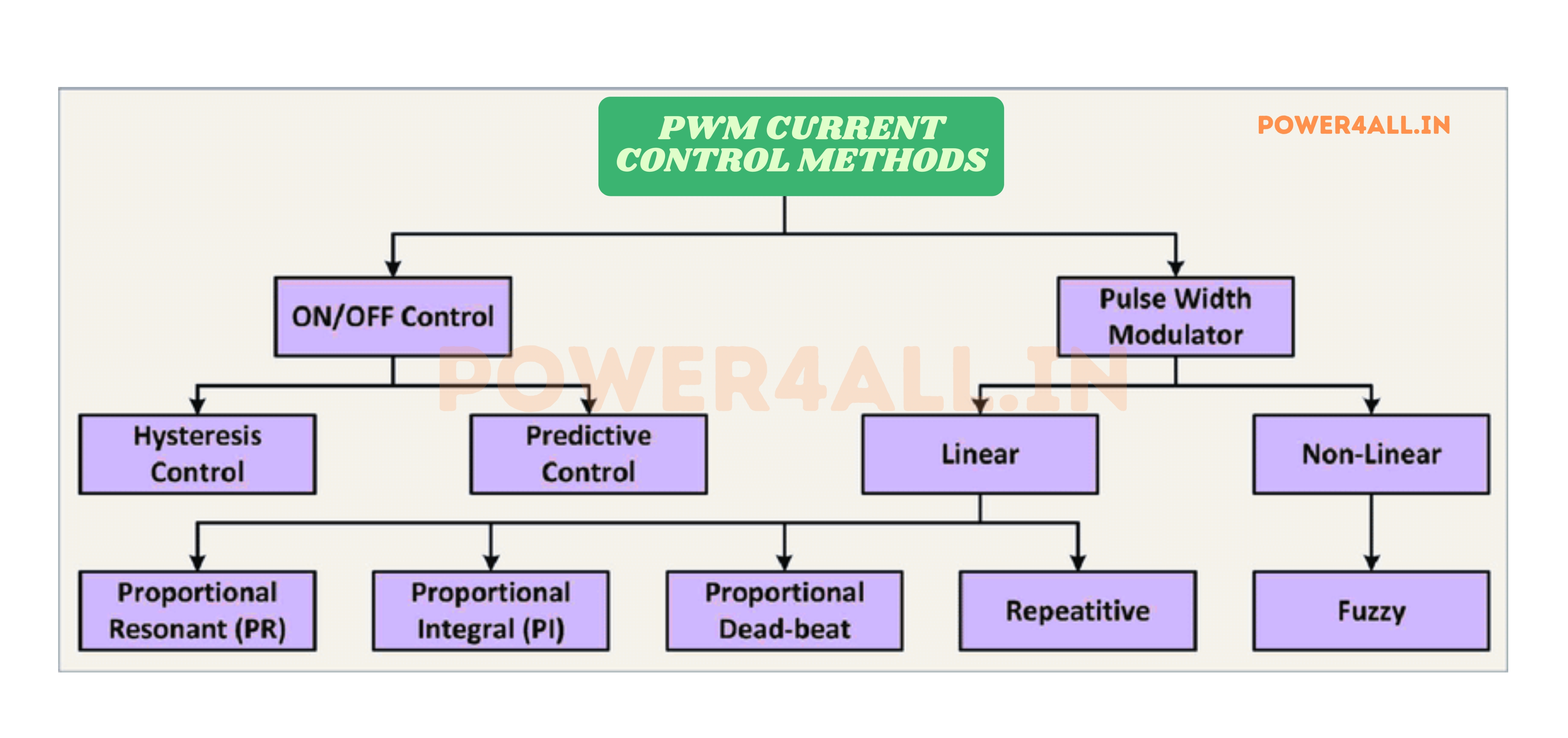
Switching Current Regulators
- PWM control: High-frequency switching
- High efficiency: 85-95% typical
- Complex control: Requires sophisticated feedback
- Applications: LED drivers, battery chargers
Current Sensing and Feedback
Current Measurement for Control Systems
Current Sensing Techniques
| Sensing Method | Principle | Accuracy | Bandwidth | Applications |
|---|---|---|---|---|
| Shunt Resistor | Ohm's law (V = I×R) | ±0.1% - ±1% | DC - 100MHz | Precision current measurement |
| Hall Effect Sensor | Magnetic field detection | ±1% - ±3% | DC - 1MHz | Isolated current sensing |
| Current Transformer | Magnetic coupling | ±0.1% - ±0.5% | 50Hz - 10kHz | AC power systems |
| Rogowski Coil | Mutual inductance | ±1% - ±2% | 1Hz - 1MHz | High current AC measurement |
| Fluxgate Sensor | Magnetic flux measurement | ±0.01% - ±0.1% | DC - 100kHz | Precision DC current measurement |
Feedback Control Systems
I_error = I_reference - I_measured
Current error drives control system adjustment
PID Current Control
- Proportional: Immediate response to current error
- Integral: Eliminates steady-state error
- Derivative: Improves transient response
- Tuning: Critical for stable operation
Hysteretic Control
- Bang-bang control: On/off switching
- Current ripple: Controlled within band
- Fast response: Excellent transient performance
- Variable frequency: Switching rate varies
Specialized Current Control Applications
LED Current Control
Constant current for consistent brightness and lifetime
LED Characteristics
- Forward voltage variation: ±10% between LEDs
- Temperature effects: Forward voltage decreases with heat
- Current sensitivity: Small current changes affect brightness
- Thermal runaway: Requires current limiting
High-Power LED Driver Design
1A LED driver specifications:
- Output current: 1000mA ±1%
- Input voltage: 12V - 24V DC
- Current sensing: 0.1Ω precision shunt
- Control method: Buck converter with current mode control
- Efficiency: >90% at full load
- Dimming: PWM or analog control input
Battery Charging Current Control
Multi-stage charging with precise current control
Charging Phases
- Pre-charge: Low current (C/10) for deeply discharged batteries
- Constant current: High current (C/2 to 2C) main charge
- Constant voltage: Current tapers as battery approaches full charge
- Maintenance: Very low current to maintain charge
Current Control Requirements
- Accuracy: ±5% current regulation
- Temperature compensation: Adjust for battery temperature
- Safety limits: Overcurrent and thermal protection
- Communication: Battery management system interface
Motor Current Control
Torque control through current regulation
Motor Control Methods
- Direct current control: Torque proportional to current
- Field-oriented control: Separate flux and torque currents
- Direct torque control: Rapid torque response
- Sensorless control: Estimate position from currents
Current Loop Performance
- Bandwidth: >1kHz for good dynamic response
- Current ripple: <10% of rated current
- Overload capability: 150-200% for short periods
- Protection: Overcurrent, ground fault, phase loss
Current Limiting and Protection
Electronic Circuit Breakers
Fast-acting current limiters that can interrupt fault currents in microseconds, protecting sensitive electronics.
Thermal Current Limiting
PTC devices and thermal fuses that limit current when temperature rises, providing inherent overload protection.
Arc Fault Protection
Advanced current monitoring that detects dangerous arcing conditions and interrupts current to prevent fires.
Smart Current Management
IoT-enabled current monitoring and control systems that optimize performance and predict maintenance needs.
Frequently Asked Questions
Common questions about electric current, answered with practical insights and real-world examples to deepen your understanding.
Basic Current Concepts
Q: What's the difference between current and voltage?
A: Current is the flow of electric charge (like water flow), while voltage is the electrical pressure that pushes the current through a circuit (like water pressure). You need both for electrical power: P = V × I. Think of it this way: voltage is the potential to do work, current is what actually does the work.
Q: Can current flow without voltage?
A: No, under normal circumstances. Voltage creates the electric field that drives current flow. However, in superconductors, once current is established, it can flow indefinitely without additional voltage due to zero resistance. This is called a "persistent current."
Q: Why do electrons flow slowly but lights turn on instantly?
A: Individual electrons move very slowly (about 1mm/second), but the electric field that pushes them propagates at nearly the speed of light. It's like a tube full of marbles - push one end, and a marble immediately comes out the other end, even though each marble moves slowly.
Q: What determines how much current flows in a circuit?
A: Three main factors: the applied voltage (higher voltage = more current), the resistance of the path (lower resistance = more current), and the characteristics of the load. Ohm's Law (I = V/R) governs this relationship for resistive circuits.
Current Safety
Q: How much current is dangerous to humans?
A: As little as 10mA can cause muscular paralysis (you can't let go), and 100mA can cause ventricular fibrillation and death. However, the actual current depends on voltage and body resistance. Wet skin dramatically reduces resistance, making even low voltages dangerous. This is why GFCI devices trip at 5mA.
Q: Why is high voltage dangerous if current is what kills?
A: High voltage can drive dangerous current through your body's resistance. While dry skin might have 50kΩ resistance (limiting 120V to 2.4mA), cuts, moisture, or high voltage can reduce effective resistance dramatically. 10,000V can easily drive lethal current even through high resistance.
Q: Can you feel electric current?
A: Yes! You can feel as little as 1mA as a tingling sensation. 5mA is painful, and 10mA causes muscular control loss. The sensation is caused by current stimulating your nerves. Static electricity can be thousands of volts but is harmless because the current is extremely brief and small.
Q: Why don't birds get electrocuted on power lines?
A: Birds don't complete a circuit to ground or another voltage level. They're at the same potential as the wire they're on, so no current flows through them. If a bird touched two wires at different voltages or touched a wire while grounded, it would be electrocuted.
Current Measurement
Q: Why must current be measured in series?
A: Current is the flow of charge, so you must insert the meter into the current path to measure how much charge is flowing past a point. Unlike voltage (which exists between two points), current flows through a path. It's like measuring water flow - you must put the flow meter in the pipe.
Q: How do clamp meters work without breaking the circuit?
A: Clamp meters detect the magnetic field created by current flow. AC current creates a changing magnetic field that induces voltage in the clamp's sensor coil. DC clamp meters use Hall effect sensors that detect magnetic fields directly. The current in the wire is proportional to the magnetic field strength.
Q: Why do my current readings fluctuate?
A: Several reasons: varying loads (motors cycling on/off), loose connections causing resistance changes, magnetic interference affecting clamp meters, or measuring reactive loads where current varies with the AC waveform. Use averaging or min/max functions to capture the full picture.
Practical Applications
Q: Why do motors draw more current at startup?
A: When a motor is stationary, there's no back-EMF to oppose the applied voltage, so more current flows (6-8× normal). As the motor speeds up, it generates back-EMF that opposes the applied voltage, reducing current. It's like pushing a heavy object - takes more force to start moving than to maintain motion.
Q: How do LED drivers maintain constant current?
A: LED drivers use feedback control systems. They measure the LED current and adjust their output to maintain the desired level. This is crucial because LEDs have a sharp voltage-current characteristic - small voltage changes cause large current changes, which affects brightness and lifetime.
Q: Why can't you just use a resistor to limit current?
A: You can, but it's inefficient. A resistor drops voltage and wastes power as heat. For a 1A LED that needs 3V from a 12V supply, you'd waste 9W in the resistor to deliver 3W to the LED - only 25% efficient! Switching regulators achieve 90%+ efficiency.
Q: What causes harmonics in current waveforms?
A: Non-linear loads like switch-mode power supplies, variable frequency drives, and LED drivers don't draw sinusoidal current even when supplied with sinusoidal voltage. They draw current in pulses or with sharp edges, creating harmonics that can cause heating, interference, and power quality problems.
Conclusion: Mastering Electric Current for the Future
Electric current is the fundamental force that powers our modern world, from the smallest microelectronic circuits to massive industrial systems. Understanding current principles, measurement techniques, and control methods opens doors to innovation and problem-solving across countless applications.
Key Takeaways
Fundamental Understanding
Current is the flow of electric charge, measured in amperes. It's the actual movement of electrons that enables all electrical work, from powering devices to processing information.
Safety is Paramount
Current is what causes injury in electrical accidents. Understanding current effects on the human body and implementing proper safety measures literally saves lives.
Measurement and Control
Accurate current measurement and precise control are essential skills for electrical work. From simple meters to sophisticated control systems, these tools enable safe and effective electrical systems.
Emerging Technologies
Advanced materials, AI-powered control, and quantum effects are revolutionizing current applications. The future promises even more efficient and capable current-based technologies.
The Current Revolution
We are experiencing unprecedented advances in current technology. Electric vehicles are transforming transportation with sophisticated current control systems that maximize efficiency and performance. Renewable energy systems use advanced current conversion to integrate seamlessly with the grid. Data centers are pushing the boundaries of high-current, low-voltage systems for maximum computational efficiency.
The Internet of Things demands ultra-low current operation for battery-powered devices that last years on a single charge. Meanwhile, industrial processes require precise current control for everything from LED manufacturing to aluminum smelting. These diverse applications showcase the versatility and critical importance of understanding current in all its forms.
Final Thoughts
Current is simultaneously one of the most fundamental and most sophisticated aspects of electrical engineering. Whether you're designing a simple LED circuit or a complex motor drive system, understanding current behavior is essential for success.
Remember that electrical work involves real risks - current can injure or kill. But with proper knowledge, tools, and safety procedures, you can work confidently with electrical systems while advancing the technology that powers our world.
The field of electrical engineering continues to evolve rapidly, driven by environmental needs, technological advances, and human creativity. Current - in all its forms - will remain at the heart of these developments, enabling the innovations that will shape our future.
Thank You for Learning About Current
We hope this comprehensive guide has enhanced your understanding of electric current and inspired you to continue learning. Whether you're troubleshooting a simple circuit or designing the next generation of power electronics, remember that current is the flowing force that makes it all possible.