Single Phase Full Wave Controlled Rectifier
A fundamental AC to DC converter using four SCRs, ideal for demonstrating phase control and providing adjustable, smoother DC output for various power applications.
- Introduction
- What is the Single Phase Full Wave Controlled Rectifier
- Working of Single Phase Full Bridge Converter With R Loadr
- Key Equations: Single Phase Half-Wave Controlled Rectifier
- Full Controlled Rectifier With R Load Output Waveform
- Advantages
- Disadvantages
- Frequently Asked Questions – FAQs
- Related Topics
Introduction
The Single Phase Full Wave Controlled Rectifier employs both positive and negative halves of the AC power supply, resulting in a heightened effective DC voltage and reduced ripple content compared to half-wave rectifiers. Two primary configurations of Single Phase Full Wave Controlled Rectifiers are distinguished based on their configuration type: mid-point converters and bridge converters.
What is the Single Phase Full Wave Controlled Rectifier
In a single-phase full-wave controlled rectifier (1-Phase FWR), all four silicon-controlled rectifiers (SCRs) are utilized, enabling output voltage generation for both positive and negative cycles.
These devices are employed to convert alternating current (AC) to direct current (DC) while allowing for the regulation of the output voltage. This is accomplished by manipulating the firing angle (or phase angle) of thyristors, which are semiconductor devices capable of switching high currents.
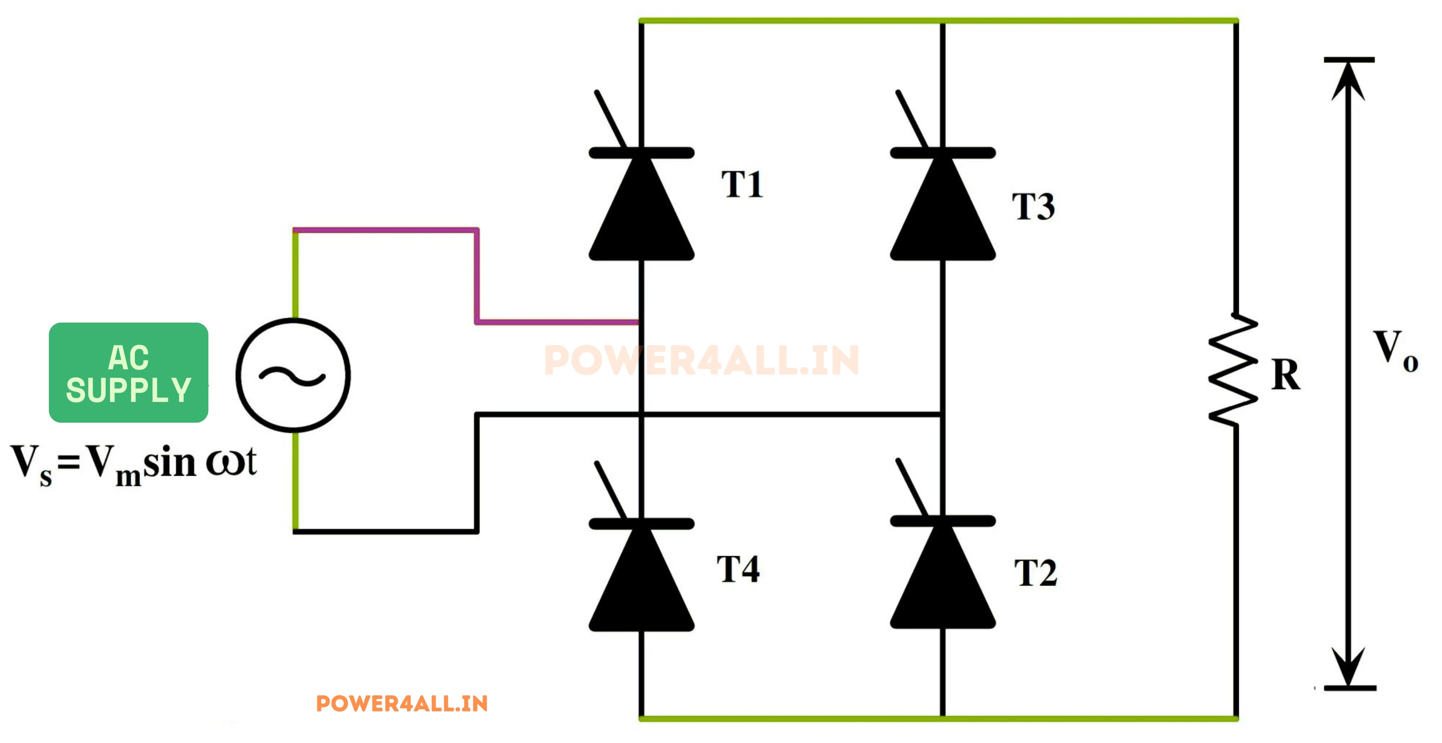
Working of Single Phase Full Bridge Converter With R Load
Mode-I: Positive Half-Cycle
The thyristor conducts at the firing angle α during the positive half-cycle of the input AC voltage. This allows current to flow through both the load (R) and the thyristor (T1 & T2) simultaneously.
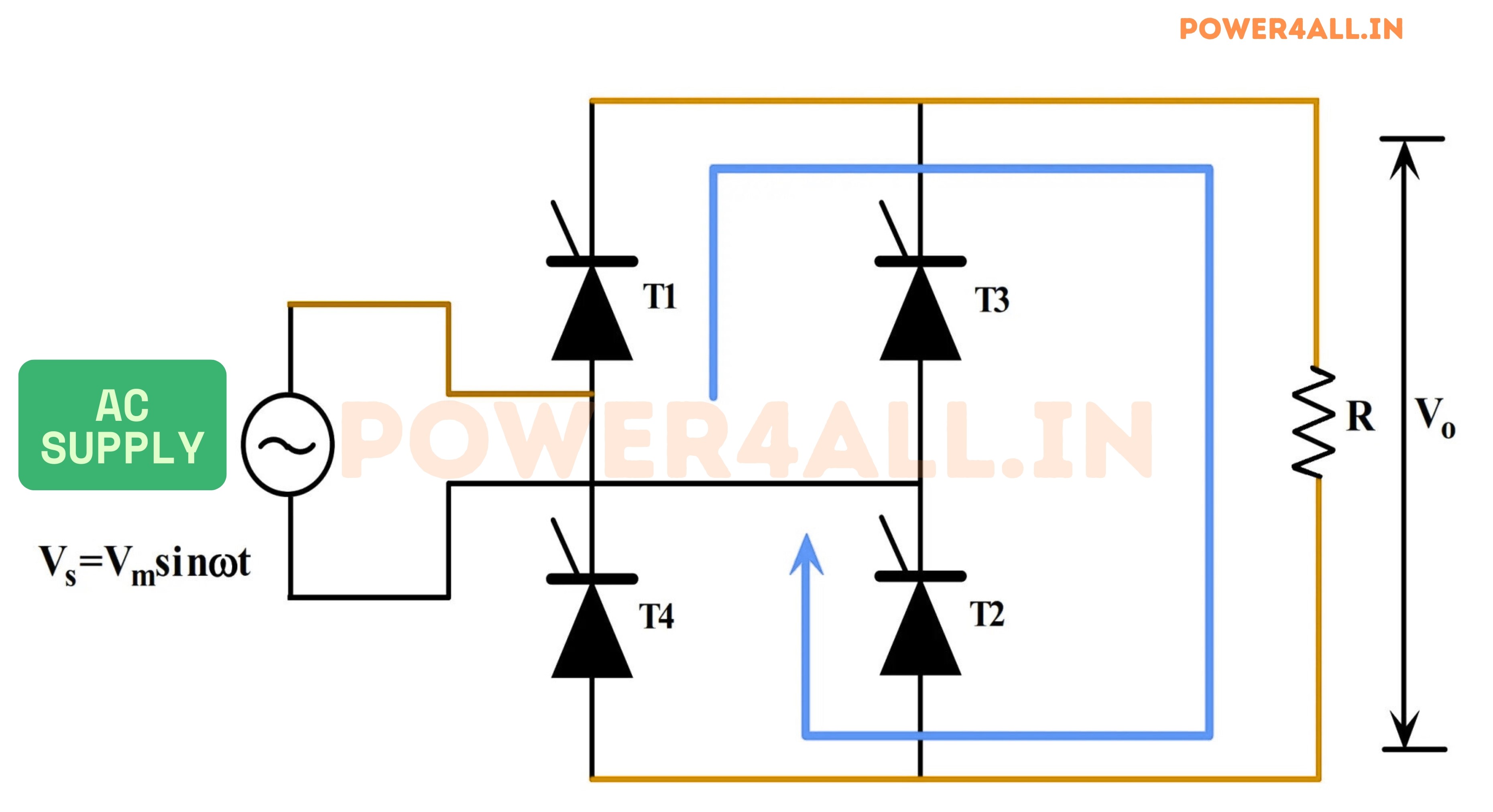
At the conclusion of the positive half-cycle, the input voltage undergoes a polarity change, leading to the automatic deactivation of the thyristor.
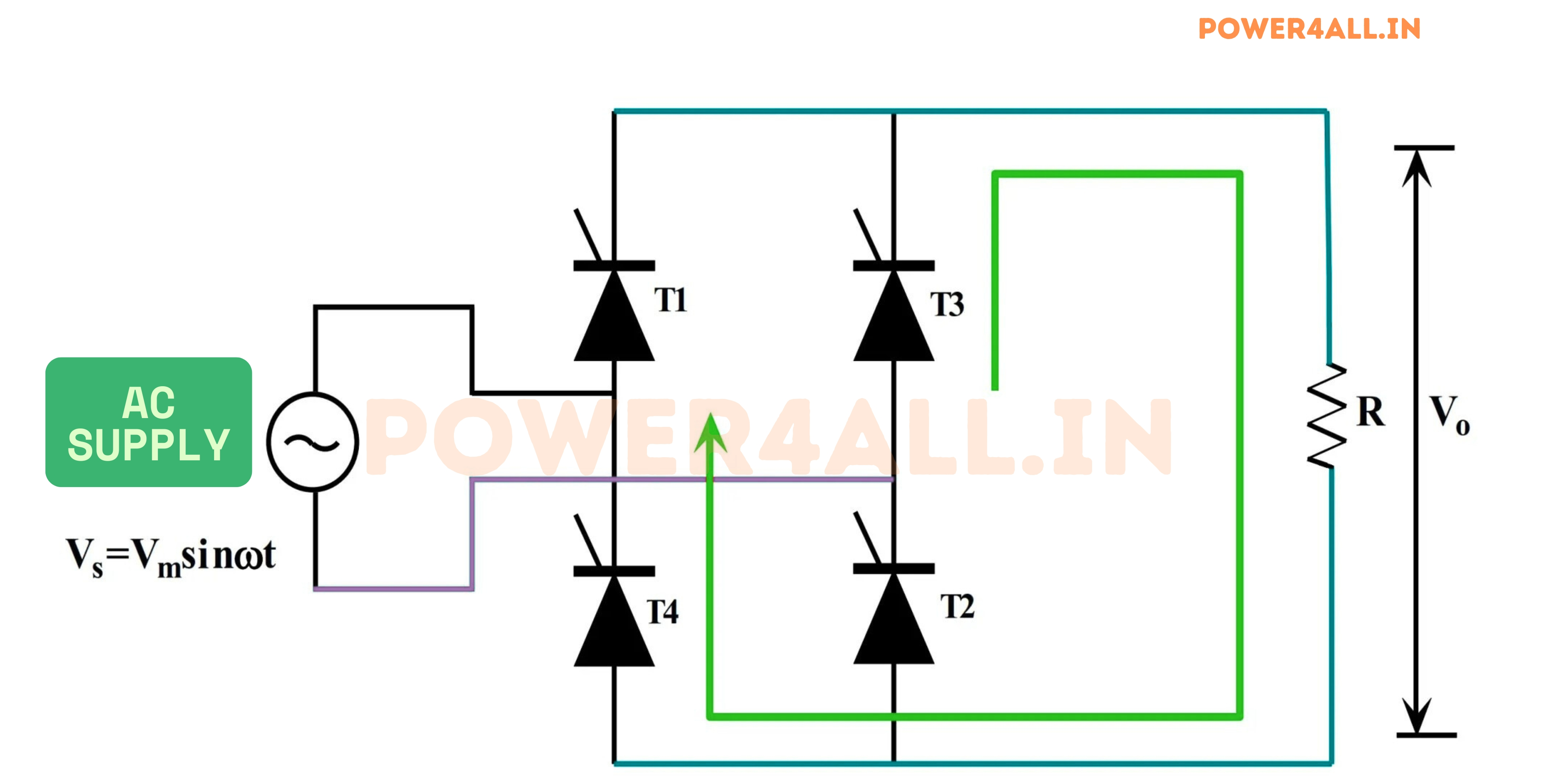
Mode-II: Negative Half-Cycle
The thyristor (T1 & T2) remains in a reverse-biased state and does not conduct during the negative half-cycle of the input AC voltage. However, during this phase, the thyristors (T3 & T4) conduct, allowing current to flow through the load.
The output voltage and current both exhibit positive cycles within this configuration. This is attributed to the load remaining positive with respect to the ground over the entirety of both cycles.
During the positive cycle, the thyristor (T3 & T4) is non-conductive, and the input voltage undergoes a polarity change, leading to the natural turn-off of the thyristor.
The computation of the average voltage (VO) across the load R in a single-phase full-wave circuit is executed by the following method:
Key Equations: Single Phase Half-Wave Controlled Rectifier
$$ V_{dc} = \frac{1}{\pi} \int_{\alpha}^{\pi} V_m \sin \omega t \, d(\omega t) $$
$$ \quad = \frac{V_m}{\pi} (1 + \cos \alpha) $$
The maximum value of \( V_{dc} \) is obtained at \( \alpha = 0^\circ \).
$$ I_{dc} = \frac{V_{dc}}{R} $$
The single-phase half-wave controlled rectifier's RMS voltage is determined:
$$ V_{RMS} = \sqrt{ \frac{1}{\pi} \int_{\alpha}^{\pi} \left[ V_m \sin \omega t \right]^2 d(\omega t) } $$
$$ \quad = \frac{V_m}{\sqrt{2\pi}} \sqrt{ \pi - \alpha + \frac{\sin 2\alpha}{2} } $$
$$ I_{RMS} = \frac{V_{RMS}}{R} $$
*Where \( V_m \) is the peak value of the input AC voltage, \( \alpha \) is the firing angle, and \( R \) is the load resistance.
Full Controlled Rectifier With R Load Output Waveform
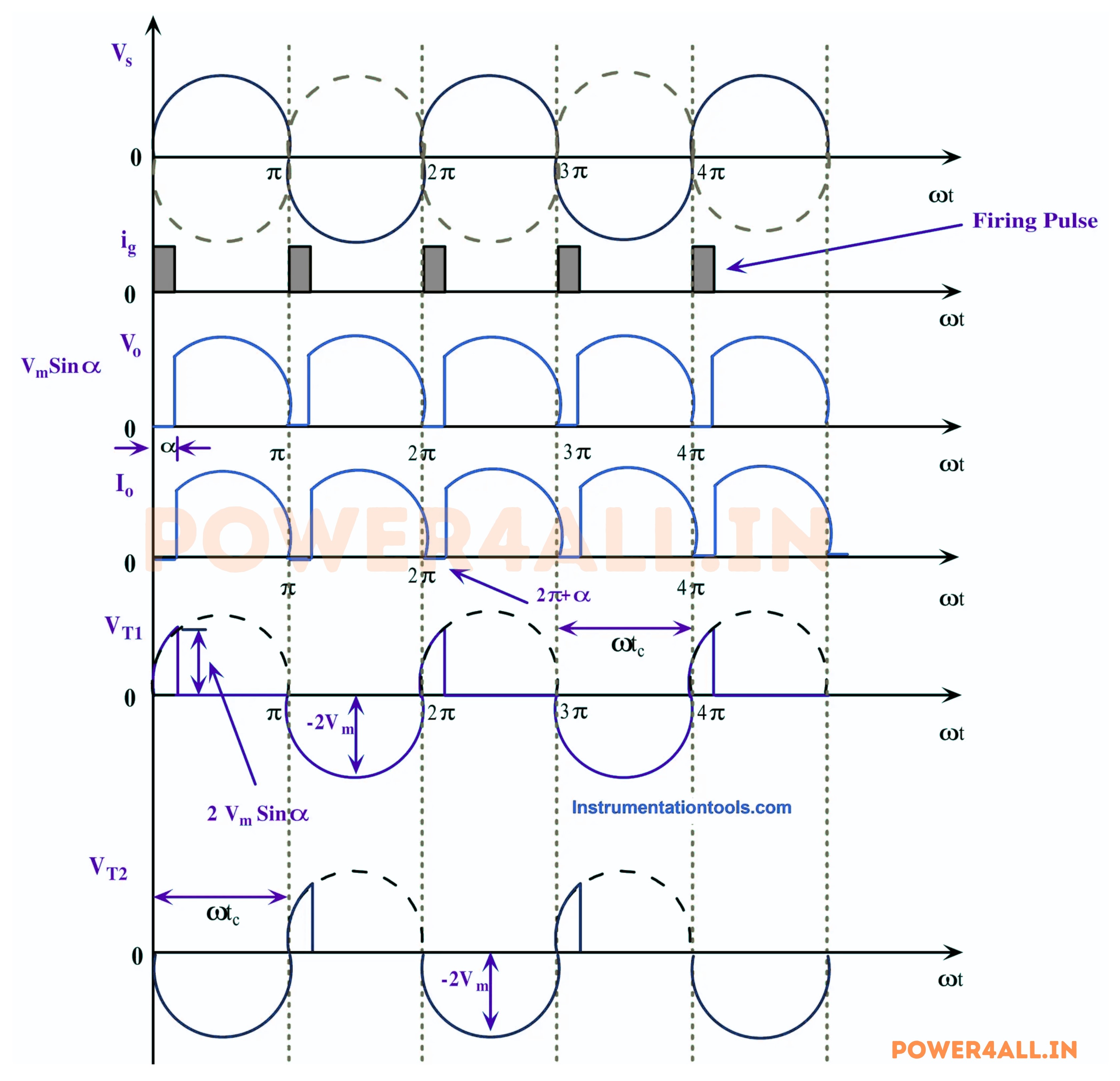
Thyristor T is forward biased for the positive half cycle of supply voltage. The load output voltage is zero till SCR is fired. Once SCR is fired at an angle of α, SCR starts conducting. But as soon as the supply voltage becomes zero at ωt = π, the load current will become zero and after ωt = π, SCR is reversed biased. Thus thyristor T will turn off at ωt = π and will remain in OFF condition till it is fired again at ωt = (2π+α).
Therefore, the load output voltage and current for one complete cycle of input supply voltage may be written as
- Vo = VmSinωt for α≤ωt≤ π
- Io = VmSinωt / R for α≤ωt≤ π
Advantages
- Controlled Output Voltage:.By adjusting the firing angle of the SCRs, the output voltage can be controlled over a wide range.
- Improved Efficiency:Full-wave rectification provides higher efficiency than half-wave rectifiers because it uses both halves of the AC waveform.
- Reduced Ripple:The full-wave rectifier produces a smoother DC output with less ripple compared to a half-wave rectifier.
- Higher Transformer Utilization Factor (TUF):The full-wave rectifier utilizes the transformer more efficiently, reducing the size and cost of the transformer required.
- Better Performance with Reactive Loads:It provides better performance and control when used with reactive loads (inductive or capacitive).
Disadvantages
- Complex Control Circuit:The control circuit for adjusting the firing angle of the SCRs can be complex and expensive.
- Harmonic Distortion:The use of SCRs can introduce harmonic distortion into the power system, affecting the power quality.
- Commutation Problems:Commutation or the process of turning off the SCRs can be problematic, especially under high load conditions.
- Size and Cost:The inclusion of additional components for phase control and filtering increases the size and cost of the rectifier.
- Heat Dissipation:o SCRs generate significant heat during operation, requiring effective cooling mechanisms to prevent overheating.