CUK Converter Calculator
Design and analyze CUK (inverting DC-DC) converters for power electronics.
Enter Design Parameters for CUK Converter
Enter all parameters and click Calculate.
The Cuk converter, named after Slobodan Ćuk, produces an output voltage that is inverted relative to its input and can be either higher or lower in magnitude. In that respect it resembles the buck–boost converter — but it reaches the same result by a completely different mechanism, and that difference is the whole reason to choose it.
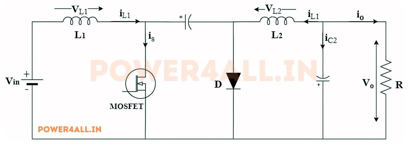
In a buck, boost or buck–boost converter, energy is passed from input to output by an inductor. In a Cuk converter it is passed by a capacitor, C1, sitting in series between the input and output stages. The switch and diode alternately charge and discharge C1, and the average voltage across it settles at |Vs|+|Vo|. C1 is therefore not a filter component — it is the main energy-transfer element, and it carries the converter's full throughput every cycle.
Because the energy transfer happens through C1, both the input and the output can keep a series inductor of their own: L1 on the input side and L2 on the output side. The practical consequence is the Cuk converter's defining advantage — both the input current and the output current are continuous rather than chopped into pulses.
A buck converter draws pulsating current from its source; a boost converter delivers pulsating current to its load. The Cuk does neither. That means markedly lower conducted EMI at the input and lower output ripple, often without the extra input filter stage a buck would need. The price is an extra inductor, an extra magnetic component to wind or buy, and a hard-working capacitor.
Applying volt-second balance to both inductors gives the steady-state relationship |Vo|/|Vs| = D/(1−D), which rearranges to the form this calculator uses: D = |Vo|/(|Vs|+|Vo|). Below D=0.5 the converter steps down; above D=0.5 it steps up; at exactly D=0.5 the output magnitude equals the input. The output polarity is negative with respect to the input ground in every case.
| Quantity | Formula | Note |
|---|---|---|
| Duty cycle | D = |Vo| / (|Vs| + |Vo|) | D<0.5 steps down, D>0.5 steps up |
| Output current | Iout = Pout / |Vo| | assumes 100% efficiency |
| Input current | Iin = Pout / |Vs| | average, continuous |
| Input inductor | L1 = Vs·D / (ΔIL1·fsw) | ΔIL1 = ripple% of Iin |
| Output inductor | L2 = Vo·(1−D) / (ΔIL2·fsw) | ΔIL2 = ripple% of Iout |
| Transfer capacitor | C1 = Iout·D / (ΔV·fsw) | ΔV = ripple% × Vo |
| Output capacitor | C2 = ΔIL2 / (8·fsw·ΔV) | standard LC output-ripple form |
| Equivalent load | R = |Vo| / Iout | for simulation / bench testing |
Because C1 carries the converter's entire energy throughput, its RMS ripple-current rating matters far more than its capacitance value. The capacitance from the formula above only sets the voltage ripple; the current rating decides whether the part survives. A capacitor chosen purely on microfarads will run hot and fail early.
This rules out ordinary aluminium electrolytics in most designs: their ESR is high, so the ripple current heats them directly, and their lifetime roughly halves for every 10 °C of temperature rise. Metallised polypropylene film and low-ESR ceramic parts are the usual choices. C1 must also be rated for at least |Vs|+|Vo|, the DC voltage it sits at in steady state, with normal derating margin on top.
One more practical note: with ceramic capacitors, remember that DC bias can strip away a large fraction of the nameplate capacitance at the working voltage, so check the manufacturer's bias curve rather than trusting the printed value.
Given: Input Voltage (Vs) = 325 V, Output Voltage (Vo) = 100 V, Output Power (Pout) = 500 W, Ripple = 10%, Switching Frequency (fsw) = 50,000 Hz
Given: Input Voltage (Vs) = 10 V, Output Voltage (Vo) = 15 V, Output Power (Pout) = 30 W, Ripple = 10%, Switching Frequency (fsw) = 100,000 Hz
Given: Input Voltage (Vs) = 24 V, Output Voltage (Vo) = 12 V, Output Power (Pout) = 60 W, Ripple = 10%, Switching Frequency (fsw) = 75,000 Hz
A Cuk converter is a DC-DC converter whose output voltage is inverted (negative with respect to the input ground) and can be either larger or smaller in magnitude than the input. Unlike buck, boost and buck-boost converters, which pass energy from input to output through an inductor, the Cuk passes it through a series capacitor.
D = |Vo| / (|Vs| + |Vo|), which is the rearranged form of the conversion ratio |Vo|/|Vs| = D/(1−D). A duty cycle below 0.5 steps the voltage down, above 0.5 steps it up, and exactly 0.5 gives an output magnitude equal to the input.
Both invert the output and can step up or down, but the buck-boost transfers energy through its inductor while the Cuk transfers it through capacitor C1. Because the Cuk can therefore keep a series inductor on both the input and the output side, both its input and output currents are continuous, whereas a buck-boost chops both.
L1 on the input side and L2 on the output side are what make both currents continuous. Since the energy itself travels through capacitor C1 rather than through an inductor, neither inductor has to be interrupted to move power across the converter, so each one can stay in series with its own port and smooth that port's current.
Continuous, non-pulsating current at both the input and the output. That means much lower conducted EMI at the source and low output ripple, often removing the need for the separate input filter stage a buck converter of the same rating would require.
Component count and stress. It needs two inductors instead of one, and capacitor C1 must handle the converter's entire energy throughput, so it needs a high ripple-current rating and a voltage rating above |Vs|+|Vo|. The inverted output polarity also complicates feedback sensing and any shared-ground system.
Size the capacitance from C1 = Iout·D/(ΔV·fsw), but select the actual part on its RMS ripple-current rating, which is what determines whether it survives. Metallised polypropylene film or low-ESR ceramic are the usual choices; ordinary aluminium electrolytics generally run too hot because their ESR converts that ripple current straight into self-heating.
In steady state C1 sits at a DC voltage of |Vs|+|Vo|, so that is the minimum, with normal derating margin on top. For the 325 V to 100 V example on this page that is 425 V before derating, so a 630 V film capacitor would be a typical choice.
It follows from the circuit topology: the energy-transfer capacitor and the output inductor are arranged so that the output node swings below the common ground reference. If a positive output is required, either the load must float or an isolated (transformer-coupled) variant of the converter must be used.
It shrinks every reactive component — L1, L2, C1 and C2 all scale inversely with fsw, which is clear from each formula in the table above. The cost is higher switching loss in the transistor and diode, more gate-drive power, and greater sensitivity to layout parasitics, so the frequency choice is a direct trade between magnetic size and efficiency.
It sets both the peak-to-peak inductor current ripple, as a percentage of the average current in each inductor, and the capacitor voltage ripple ΔV as a percentage of the output voltage. Raising it gives smaller inductors and capacitors but a rougher waveform; lowering it does the reverse.
Cuk Converter Theory Guide • Cuk Converter Simulation • SEPIC Calculator • ZETA Calculator • Buck-Boost Calculator • All Calculators

Written and reviewed by
Lead Electronic Engineer (R&D) · Power Electronics Specialist · M.E. Power Electronics
Founder of Power4All. Works in power-electronics R&D and writes the converter guides, calculators and simulators on this site.
Last updated