AC-DC · Power Factor Correction · Virtual Lab

Interleaved PFC Converter Simulator

An advanced, physics-accurate simulator of the interleaved (two-phase) boost PFC converter — two boost stages operating 180° out of phase so their input-current ripples cancel, halving the EMI filter while each leg carries half the current. Watch every waveform on a real-time oscilloscope: both interleaved leg currents and their low-ripple sum, the input voltage and current in phase (unity power factor), the duty-cycle modulation and the 100/120 Hz output ripple — validated live against ΔVo = Po/(2·ωline·C·Vo), with power factor, %THD and the boost ratio.

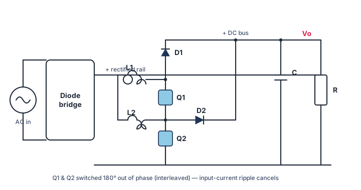
Two-phase interleaved boost PFC circuit diagram: a diode bridge feeding two parallel boost legs L1/Q1/D1 and L2/Q2/D2 switched 180 degrees out of phase into a shared DC-bus capacitor and load, giving cancelled input-current ripple and unity power factor
Two-phase interleaved boost PFC — two boost legs switched 180° apart share the current and cancel input-current ripple. Unity power factor, regulated bus Vo > Vm. (schematic)

Parameters

V
Line RMS. Peak Vm = √2·Vs.
Must be above the input peak Vm (boost only steps up).

Power stage

Bigger C ⇒ smaller 100/120 Hz ripple.
Sets the boost inductor ripple amplitude.

Display

Presets

Waveforms to display

Waveforms Vo = 400 V · 1000 W

LIVE

Power factor & harmonics (topic-specific)

An interleaved PFC runs two boost legs in parallel, 180° out of phase. When one leg's inductor current is rising the other's is falling, so their switching ripples partly cancel in the total input current — the input ripple can drop to a quarter or less, shrinking the EMI filter. Each leg carries half the current, easing thermal design and allowing phase-shedding at light load. Power factor, boost operation and the 100/120 Hz output ripple are the same as a single-leg boost PFC.

Input-current harmonic spectrum

Input-current THD
Odd harmonics of the line frequency. A good PFC keeps every harmonic tiny relative to the fundamental (bar 1).

Measurements

Live accuracy check — simulation vs closed-form theory

What is an interleaved PFC?

An interleaved PFC is a boost power-factor-correction stage split into two (or more) parallel legs whose switches are driven 180° out of phase (for N phases, 360°/N apart). It keeps all the benefits of the ordinary boost PFC — unity power factor, regulated DC bus — while adding ripple cancellation and current sharing.

Ripple cancellation — topic-specific

Because the two legs switch half a period apart, the peaks of one leg's triangular ripple line up with the valleys of the other. When the currents add at the input, much of the ripple cancels: for two phases the input-current ripple can fall to a quarter of a single leg's, and it goes to zero at 50% duty. The effective ripple frequency doubles, so the EMI filter is smaller and lighter.

Current sharing and phase shedding

Each leg carries half the total current, so the inductors, switches and diodes run cooler and can be smaller. At light load the controller can turn one leg off — phase shedding — to keep efficiency high. This makes interleaved PFCs the standard choice for high-power supplies (kW-class servers, chargers).

Vo > Vm = √2·Vs , ΔVo(amplitude) = Po/(2·ωline·C·Vo) , input ripple ↓ with interleaving

Note on the diagram

This page uses a clean schematic of the two-phase interleaved boost PFC; the simulator's waveforms are the exact numerical result. Compare the boost PFC and the bridgeless / totem-pole PFC.

Frequently asked questions

What is an interleaved PFC?

A boost PFC split into two or more parallel legs driven 180° (or 360°/N) out of phase. It gives unity power factor and a regulated DC bus like a boost PFC, plus input-current ripple cancellation and current sharing between the legs.

How does interleaving cancel ripple?

The legs switch half a period apart, so one leg's ripple rises while the other's falls. Adding the currents at the input cancels much of the ripple — for two phases it can drop to a quarter, and to zero at 50% duty — and the effective ripple frequency doubles.

What is phase shedding?

At light load the controller turns off one leg so the remaining leg runs at a more efficient operating point. As load rises the second leg is switched back on. This keeps efficiency high across the whole load range.

Does interleaving change the output ripple?

No. The low-frequency 100/120 Hz DC-bus ripple still follows ΔVo = Po/(2·ωline·C·Vo). Interleaving reduces the high-frequency input-current ripple, not the line-frequency output ripple.

Power4All · Interleaved PFC Converter interactive simulator. All waveforms are produced by numerical integration of the actual converter and validated against closed-form theory.