What is a bridgeless / totem-pole PFC?
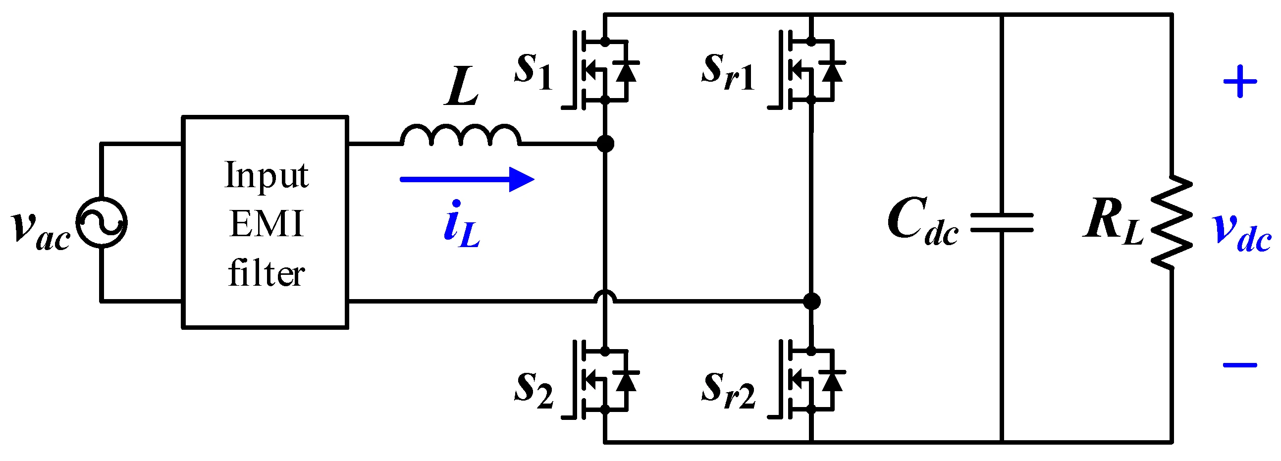
A bridgeless totem-pole PFC is a boost power-factor-correction stage that removes the input diode bridge. In an ordinary boost PFC the line current flows through two bridge diodes and the boost switch, so three devices drop voltage at once. The totem-pole topology places the boost inductor on the AC side and uses a fast switching leg (two high-frequency switches, usually GaN or SiC) plus a slow leg that rectifies at line frequency, so far fewer devices conduct at any instant.
Why it is more efficient
Fewer series devices in the current path means lower conduction loss, which is why totem-pole PFCs routinely exceed 99% efficiency. The trade-off is that the fast leg must switch hard-commutated in continuous conduction mode, which only became practical with wide-bandgap (GaN/SiC) devices that have negligible reverse-recovery charge.
Bidirectional inductor current
Because there is no bridge, the boost inductor carries the full sinusoidal line current — positive on one half-cycle and negative on the other — rather than a rectified |sin|. The current-shaping goal is identical: force the line current to be a sinusoid in phase with the voltage for unity power factor. The DC bus is still boosted above the input peak and still carries the single-phase 100/120 Hz ripple.
Applications
High-efficiency server, telecom and EV-charger front ends where every fraction of a percent of efficiency matters. Compare the ordinary boost PFC and the interleaved PFC.
Frequently asked questions
What is a bridgeless / totem-pole PFC?
A boost PFC with the input diode bridge removed. The boost inductor carries the full line current and a fast (GaN/SiC) totem-pole leg shapes it, cutting conduction loss for very high efficiency while giving unity power factor and a regulated DC bus.
Why is it more efficient than a boost PFC?
An ordinary boost PFC conducts through two bridge diodes plus the switch at once. The bridgeless topology removes the bridge, so fewer devices drop voltage in the current path — totem-pole PFCs often exceed 99% efficiency.
Why does it need GaN or SiC devices?
The totem-pole leg is hard-switched in continuous conduction mode, so the switches must have almost no reverse-recovery charge. Wide-bandgap GaN and SiC devices make this practical; silicon MOSFETs suffer excessive reverse-recovery loss.
Does it still have 100/120 Hz output ripple?
Yes. Like any single-phase PFC the input power pulsates at twice the line frequency, so the DC bus has a ripple ΔVo = Po/(2·ωline·C·Vo).