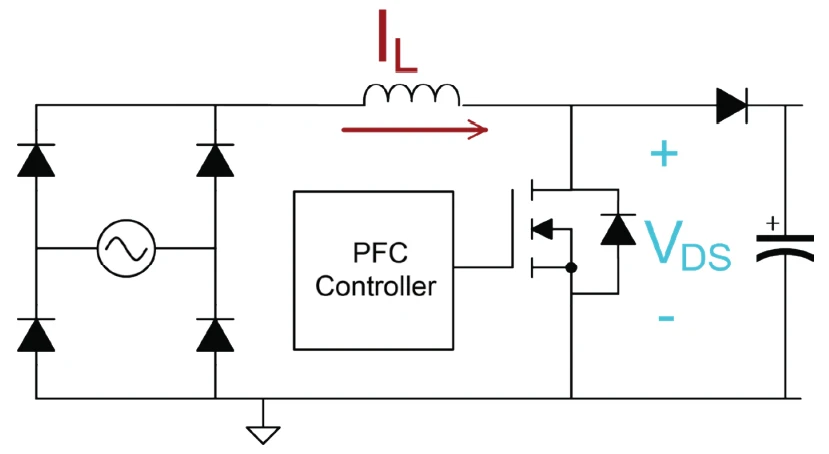
What is a boost PFC converter?
A boost power-factor-correction (PFC) converter is a diode bridge followed by a boost converter whose inductor current is actively shaped to follow the rectified input voltage. The result is a sinusoidal input current in phase with the voltage — a power factor near 1 and very low harmonic distortion — while the output is a regulated DC bus higher than the input peak. It is the standard input stage of almost every modern switch-mode power supply above ~75 W, where the IEC 61000-3-2 harmonic standard applies.
How the current is shaped — average-current-mode control
An inner current loop forces the boost inductor current to track a reference proportional to the rectified voltage, iref(t) = k·|vin(t)|. An outer voltage loop sets the scaling k to regulate the DC bus. Because the drawn current is a scaled copy of the voltage, the converter behaves like a resistor to the grid (a "resistor emulator"), giving unity power factor.
Boost operation and duty cycle
The boost stage can only step up, so the bus set-point must exceed the input peak. The duty cycle is largest (near 1) at the input zero crossings and smallest at the peak. This simulator integrates the real converter and its DC-bus capacitor, so the duty and currents are exact.
Twice-line-frequency output ripple — topic-specific
In any single-phase PFC the instantaneous input power pulsates: p(t) = Po(1 − cos 2ωlinet). The load takes the constant average, so the pulsating part flows through the DC-bus capacitor and creates a ripple at twice the line frequency (100 Hz on a 50 Hz grid, 120 Hz on 60 Hz):
This is why PFC output capacitors are large, and why three-phase PFCs such as the Vienna rectifier have almost no low-frequency ripple. The accuracy panel checks the measured ripple against this formula in real time.
Applications
Server and telecom power supplies, LED drivers, EV on-board chargers, adapters and any equipment that must meet harmonic-current limits. Related topologies: the bridgeless / totem-pole PFC (higher efficiency, no bridge) and the interleaved PFC (ripple cancellation).
Frequently asked questions
What is a boost PFC converter?
A diode bridge plus a boost converter whose inductor current is shaped to follow the rectified voltage, giving a sinusoidal input current at near-unity power factor and a regulated DC bus above the input peak.
Why must Vo be greater than the input peak?
A boost converter can only step voltage up, so the bus set-point must exceed Vm = √2·Vs. For 230 V AC (Vm ≈ 325 V) a typical bus is 390–400 V.
Why is there 100/120 Hz ripple on the DC bus?
Single-phase input power pulsates at twice the line frequency; the capacitor absorbs the difference from the constant load, giving a ripple ΔVo = Po/(2·ωline·C·Vo).
What power factor does it achieve?
Above 0.99 with THD well under 10%, meeting IEC 61000-3-2. This simulator assumes ideal current-loop tracking, so it shows essentially unity power factor.