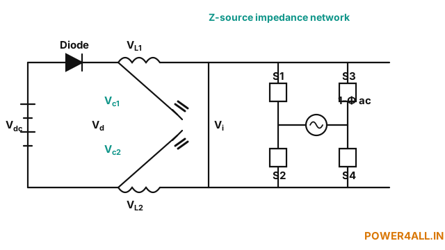
What is a Z-source inverter?
A Z-source inverter (ZSI) is a single-stage buck-boost inverter. Between the DC source and an ordinary inverter bridge it inserts a distinctive X-shaped impedance network of two inductors (L1, L2) and two capacitors (C1, C2). This lets the inverter use a shoot-through state — deliberately turning both switches of a leg on at once — which in a normal inverter would short the bus and be catastrophic, but here simply charges the inductors and boosts the DC-link voltage. As a result a single power stage can produce an AC output larger or smaller than the DC input, without a separate boost converter.
The shoot-through boost (topic-specific)
Let D0 be the fraction of each switching period spent in shoot-through. Applying volt-second balance to the Z-network inductors gives the defining relations:
Because a shoot-through interval and the active (modulation) interval must share the cycle, the modulation index and shoot-through duty are constrained by M + D0 ≤ 1. As D0 → 0.5 the boost factor tends to infinity (in practice limited by losses). This simulator integrates the real Z-network through the shoot-through and active states to steady state, so the boosted DC-link, inductor current and capacitor voltage are all exact and validated against the equations above.
How the states work
- Shoot-through state (D0·T): the bridge shorts the DC-link, the input diode blocks, and the two capacitors dump energy into the inductors — vi = 0, inductor current ramps up.
- Active / zero state ((1−D0)·T): the diode conducts, the network delivers the boosted DC-link v̂ = B·Vdc to the bridge, and the inductors transfer energy to the load and capacitors.
Z-source vs conventional VSI
| Feature | Conventional VSI | Z-source inverter |
|---|---|---|
| Voltage capability | Buck only (Vo < Vdc) | Buck & boost (Vo ≷ Vdc) |
| Shoot-through | Destructive fault | Used to boost — inherently safe |
| Stages | Boost converter + inverter | Single stage |
| Dead-time | Required | Not needed |
See also the three-phase Z-source inverter, and the conventional single-phase full-bridge and three-phase 180° inverters.
Applications
Photovoltaic and fuel-cell inverters (where the DC input varies widely), electric-vehicle drives, and any application needing a single-stage buck-boost DC-AC conversion with high reliability.
Frequently asked questions
What is the boost factor of a Z-source inverter?
B = 1/(1−2·D0), where D0 is the shoot-through duty ratio. The boosted DC-link is B·Vdc and the capacitor voltage is (1−D0)/(1−2·D0)·Vdc.
What is the AC output voltage?
Peak Vo = M·B·Vdc, so the buck-boost gain is G = M·B. The modulation index and shoot-through duty are limited by M + D0 ≤ 1.
Why is shoot-through safe here?
The Z-network inductance is in series with the bridge, so a shoot-through charges the inductors instead of shorting the source — and it is exactly what boosts the DC-link.
Z-source vs a boost converter + inverter?
The ZSI does buck-boost in a single stage with no dead-time and inherent shoot-through immunity, whereas the two-stage approach needs a separate boost converter and dead-time.