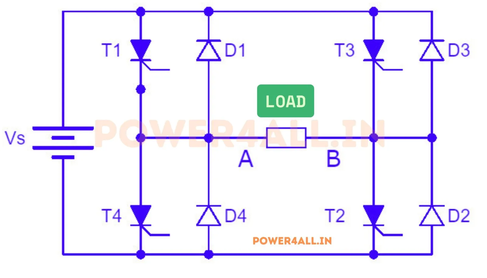
What is a single-phase full-bridge inverter?
A full-bridge (H-bridge) inverter uses four switches in two legs, with the load connected across the bridge diagonal. Turning on one diagonal pair applies +Vdc to the load; the other diagonal pair applies −Vdc. Because it swings the full ±Vdc (versus ±Vdc/2 for a half-bridge), it delivers double the output from the same DC bus, and its two legs enable extra modulation schemes.
Square-wave operation
Bipolar vs unipolar PWM (topic-specific)
With sinusoidal PWM the fundamental peak is ma·Vdc in the linear region, but the two legs can be driven two ways:
- Bipolar PWM: the legs switch in anti-phase, so the output is a two-level ±Vdc waveform. Harmonics cluster around the carrier mf.
- Unipolar PWM: each leg follows its own reference, so the output is a three-level ±Vdc/0 waveform. The lowest harmonics move up to 2·mf — as if the switching frequency doubled — giving markedly lower distortion for the same device switching frequency.
Quasi-square wave & selective harmonic elimination
A quasi-square wave places a notch of width 2β at each zero crossing. The n-th harmonic amplitude scales as cos(nβ), so setting β = 90°/n drives that harmonic to zero while the fundamental becomes (4Vdc/π)·cosβ:
This is the essence of selective harmonic elimination (SHE). Try the "Kill 3rd / Kill 5th" presets and watch that bar vanish in the spectrum.
Half-bridge vs full-bridge
| Inverter | Switches | Output swing | Fundamental (square) |
|---|---|---|---|
| Half-Bridge | 2 | ±Vdc/2 | Vo1 = 2Vdc/π |
| Full-Bridge | 4 | ±Vdc | Vo1 = 4Vdc/π |
See the half-bridge inverter and the three-phase 180° / 120° VSI simulators.
Applications
Single-phase UPS, solar string inverters, induction heating, variable-frequency drives and grid-tie stages. Unipolar PWM and SHE are widely used to meet harmonic standards with a small output filter.
Frequently asked questions
What is the output of a full-bridge inverter?
Square-wave: ±Vdc, RMS Vdc, fundamental peak 4Vdc/π. SPWM: fundamental peak ma·Vdc in the linear region.
Bipolar vs unipolar PWM?
Bipolar gives a 2-level ±Vdc output with harmonics near mf; unipolar gives a 3-level output with harmonics near 2·mf — lower distortion for the same switching frequency.
What is selective harmonic elimination?
A quasi-square notch of width 2β makes the n-th harmonic (∝ cos nβ) vanish at β = 90°/n, e.g. β = 30° kills the 3rd harmonic.
Half-bridge vs full-bridge output?
The full-bridge applies ±Vdc (fundamental 4Vdc/π) — double the half-bridge's ±Vdc/2 (2Vdc/π) from the same DC bus.