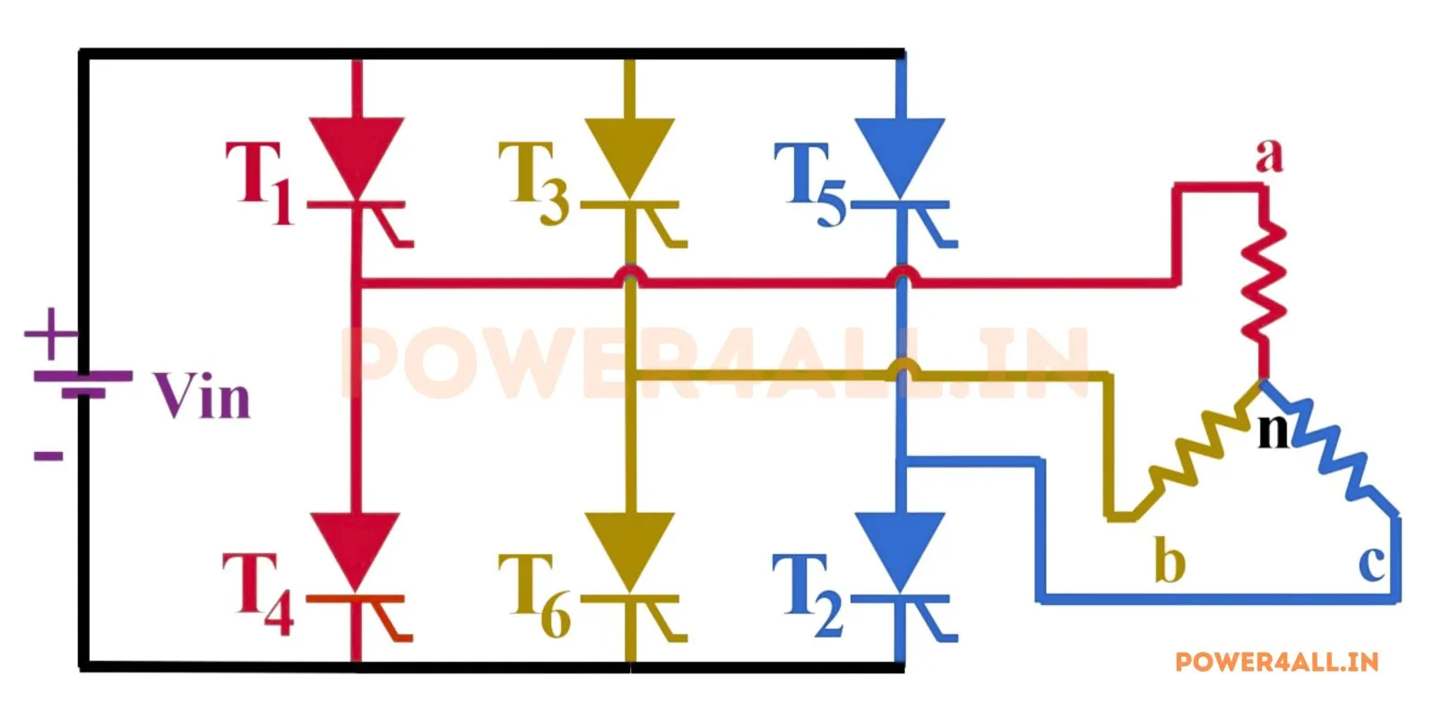
What is a three-phase 120° conduction inverter?
A three-phase voltage-source inverter can be gated in two ways. In 120° conduction mode, each of the six switches conducts for only 120° of the fundamental cycle and is off for the remaining 60°. Because of this, at any instant only two switches conduct — one upper and one lower in different legs — and the third phase is disconnected (floating) for 60°. The built-in 60° gap means the two switches of a leg can never overlap, so shoot-through is impossible without any added dead-time.
Phase & line voltages
For a balanced star load, the floating phase sits at the load star point (zero), so the phase voltage is a quasi-square wave: +Vdc/2 for 120°, zero for 60°, −Vdc/2 for 120°, zero for 60°:
This simulator integrates the actual three-leg 120° switching, so every one of the phase, line and current waveforms — all three of each — is exact and validated against the formulas above.
The 120° conduction pattern (topic-specific)
The dedicated conduction chart shows, for each phase, the 120° connection to a rail followed by the 60° float. It makes clear the defining property: only two devices conduct at a time and each phase has two 60° floating windows per cycle. During a float, the phase carries no current and its terminal rests at the star point — producing the zero plateaus in the phase voltage.
120° vs 180° conduction
| Feature | 120° conduction | 180° conduction |
|---|---|---|
| On-time / switch | 120° | 180° |
| Devices conducting | 2 at a time | 3 at a time |
| Phase floats? | Yes, 60° per half-cycle | No |
| Phase fundamental peak | √3·Vdc/π ≈ 0.551·Vdc | 2·Vdc/π ≈ 0.637·Vdc |
| Shoot-through risk | None (built-in gap) | Needs dead-time |
Compare with the three-phase 180° (six-step) inverter, and see the single-phase half-bridge and full-bridge inverters.
Applications
Three-phase motor drives and brushless-DC / PMSM control (where 120° six-step commutation is common), lower-cost drives that avoid dead-time circuitry, and teaching the contrast with 180° six-step operation.
Frequently asked questions
What is 120° conduction?
Each switch conducts for only 120° and is off for 60°, so only two devices conduct at once and each phase floats for 60°.
What is the output voltage?
Phase voltage is a quasi-square wave with fundamental peak √3·Vdc/π and RMS Vdc/√6; line fundamental peak 3·Vdc/π, THD ≈ 30.5%.
How is it different from 180° conduction?
180° has three devices conducting and a higher output (phase peak 2Vdc/π); 120° has two devices, floating phases and a built-in dead-time that prevents shoot-through.
Why does a phase float?
Each switch is off for 60°, so there is a 60° window where neither switch of a leg conducts and the phase disconnects from both rails.