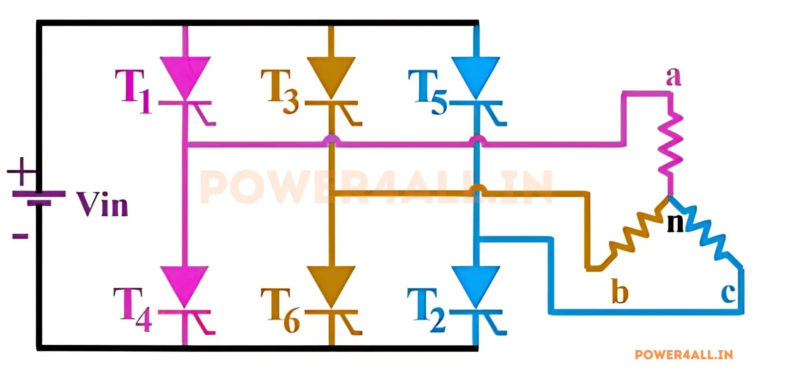
What is a three-phase 180° conduction inverter?
A three-phase voltage-source inverter (VSI) uses six switches in three legs to synthesise a three-phase AC output from a DC bus. In 180° conduction mode each switch is on for exactly half the fundamental cycle (180°), and the three legs are gated 120° apart. Because the upper and lower switch of a leg are complementary, three switches conduct at every instant — one from each leg — so the load is always fully connected. This is the classic six-step operation and gives the maximum fundamental output for a given DC bus.
Phase & line voltages
With a star-connected load whose neutral floats, the phase (line-to-neutral) voltage is the six-step waveform, with steps of ±Vdc/3 and ±2Vdc/3:
The line-to-line voltage is a 120° quasi-square wave. This simulator integrates the actual three-leg switching with the floating-neutral shift vn0 = (vA0+vB0+vC0)/3, so every waveform, RMS and THD is exact.
The six switching states & triplen harmonics (topic-specific)
As the legs switch, the inverter steps through six active states, each lasting 60° — the six active voltage vectors of space-vector modulation. A key property: the phase voltages contain triplen harmonics (3rd, 9th, 15th…), but these are co-phasal (identical) in all three phases, so they cancel in the line-to-line voltage. The line voltage therefore contains only non-triplen harmonics (5th, 7th, 11th, 13th…) and has a lower THD. The simulator's spectrum panel lets you switch between phase and line voltage and see the triplen bars disappear.
Six-step vs SPWM
Six-step gives the highest output but a fixed, harmonic-rich waveform. Three-phase SPWM compares three 120°-shifted sine references against a common carrier, giving a controllable fundamental (peak ma·Vdc/2 per phase in the linear region) and pushing the harmonics up to the carrier — much cleaner for motor drives. Toggle the modulation to compare.
180° vs 120° conduction
| Mode | Conduction / switch | Devices on | Phase fundamental |
|---|---|---|---|
| 180° | 180° | 3 at a time | 2Vdc/π ≈ 0.637·Vdc |
| 120° | 120° | 2 at a time | √3·Vdc/π ≈ 0.551·Vdc |
Compare with the three-phase 120° conduction inverter, and see the single-phase half-bridge and full-bridge inverters.
Applications
Three-phase motor drives, variable-frequency drives (VFDs), UPS, solar and wind grid-tie inverters, and traction. Six-step is used at high speed/field-weakening; SPWM and space-vector PWM dominate normal operation.
Frequently asked questions
What is 180° conduction?
Each of the six switches conducts for 180° and the legs are gated 120° apart, so three switches conduct at every instant — the standard six-step VSI.
What is the six-step output voltage?
Phase voltage: six-step, fundamental peak 2Vdc/π, RMS √2·Vdc/3. Line voltage: quasi-square, fundamental RMS √6·Vdc/π, THD ≈ 31%.
Why has the line voltage no triplen harmonics?
Triplen harmonics are identical in all three phases and cancel in the line-to-line difference, leaving only 5th, 7th, 11th, 13th…
What are the six states?
The six active voltage vectors, each held for 60° in six-step operation — the basis of space-vector modulation.