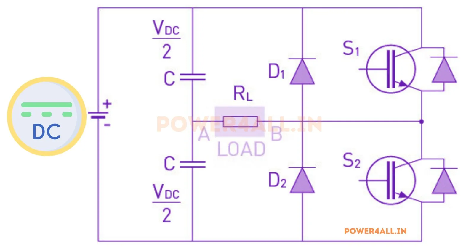
What is a single-phase half-bridge inverter?
A half-bridge inverter is the simplest voltage-source DC-AC converter. Two series capacitors split the DC bus to form a mid-point at Vdc/2, and a single leg of two switches (S1 top, S2 bottom) connects the load between that mid-point and the switch node. Turning S1 on gives +Vdc/2; turning S2 on gives −Vdc/2. Alternating them at the desired frequency produces an AC output. The two switches must never conduct together (a dead-time prevents shoot-through).
Square-wave operation
The simplest control switches S1 for the first half-cycle and S2 for the second, giving a square wave of ±Vdc/2. Its Fourier series contains only odd harmonics:
Sinusoidal PWM & the modulation index (topic-specific)
To make the output cleaner, sinusoidal PWM compares a sine reference of amplitude ma against a triangular carrier at mf = fc/f1 times the fundamental. In the linear region (ma ≤ 1):
The low-order harmonics are almost eliminated — the distortion is pushed up to sidebands around the carrier frequency, where a small L-C filter removes it easily. This simulator's spectrum panel shows this directly: raise mf and watch the harmonic bars march to the right. For ma > 1 (overmodulation) the fundamental keeps rising but low-order harmonics reappear as the output saturates toward the square-wave limit 2Vdc/π.
R-L load & current
A real load has resistance and inductance. The inductance makes the current lag the voltage by φ = arctan(ωL/R) and filters the PWM ripple, so the current is far more sinusoidal than the voltage. The simulator integrates L·di/dt = vo − R·i to steady state, so the current waveform, its RMS and its THD are all exact.
Half-bridge vs full-bridge
| Inverter | Switches | Output swing | Fundamental (square) |
|---|---|---|---|
| Half-Bridge | 2 | ±Vdc/2 | Vo1 = 2Vdc/π |
| Full-Bridge | 4 | ±Vdc | Vo1 = 4Vdc/π |
See the single-phase full-bridge inverter and the three-phase 180° / 120° VSI simulators.
Applications
Low-power UPS, small motor drives, induction heating, and as the building block for teaching PWM. The half-bridge is the two-switch foundation that the full-bridge and three-phase inverters extend.
Frequently asked questions
What is the output voltage of a half-bridge inverter?
Square-wave: peak ±Vdc/2, RMS Vdc/2, fundamental peak 2Vdc/π. With SPWM the fundamental peak is ma·Vdc/2 in the linear region.
What is the modulation index?
The ratio of the sine-reference amplitude to the carrier amplitude. ma ≤ 1 is the linear region (Vo1 = ma·Vdc/2); ma > 1 over-modulates toward the square-wave limit.
Why does SPWM reduce THD?
It moves the harmonics from low orders (3rd, 5th…) up to sidebands around the carrier frequency, which a small filter removes — leaving a clean fundamental.
Why is the current more sinusoidal than the voltage?
An inductive load has high impedance at the carrier frequency, so it filters the PWM ripple and the current lags by arctan(ωL/R).