Single-Phase AC Voltage Controller
An AC voltage controller uses two anti-parallel thyristors to vary the RMS voltage delivered to a load — while keeping the supply frequency unchanged.
Introduction
An AC voltage controller (also called an AC regulator or AC-to-AC converter) is a power-electronic circuit that takes a fixed AC supply and delivers an adjustable AC voltage of the same frequency to the load. It does this without any intermediate DC stage — the input and output are both alternating current, so it is a direct AC-to-AC converter.
The control is achieved with fast electronic switches — usually thyristors (SCRs) or a TRIAC — that are switched on part-way through each half-cycle. By choosing when in the cycle the switches turn on, the circuit decides how much of the sine wave reaches the load, and therefore how much RMS voltage the load receives. Because there are no moving parts, the response is fast, efficient and silent, which is why AC voltage controllers are used everywhere from lamp dimmers and fan regulators to industrial heaters and motor soft-starters.
This page focuses on the single-phase, full-wave AC voltage controller, which controls both the positive and the negative half-cycle of the supply.
Block Diagram
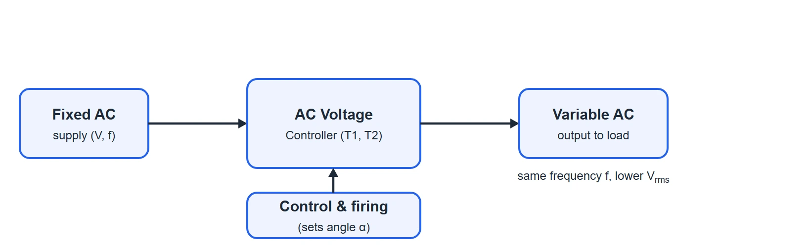
At the block level, the controller sits between a fixed AC supply and the load. A control & firing unit decides the exact instant in each half-cycle at which the thyristors are triggered. The output is AC at the same frequency as the input, but with a lower (and adjustable) RMS value.
Methods of Control
There are two common ways to vary the output of an AC voltage controller:
- Phase-angle control: in every half-cycle the thyristor is deliberately triggered after a delay, called the firing angle (α). The load is connected only for the remaining part of the half-cycle. A larger firing angle means a shorter conduction time, so less RMS voltage reaches the load. This is the method analysed in detail on this page.
- On-off (integral-cycle) control: the thyristors are left fully on for a whole number of complete cycles and then fully off for a number of cycles. The load "sees" bursts of complete sine waves. Averaged over time this reduces the effective power. It generates fewer harmonics than phase control but responds more slowly, so it suits slow thermal loads such as heaters.
Circuit Diagram & Construction
The single-phase full-wave AC voltage controller with a resistive load is built from just three parts:
- A single-phase AC supply (source voltage V).
- Two thyristors, T1 and T2, connected in anti-parallel (also called inverse-parallel or back-to-back).
- A resistive load R, carrying the output current io and output voltage Vo.
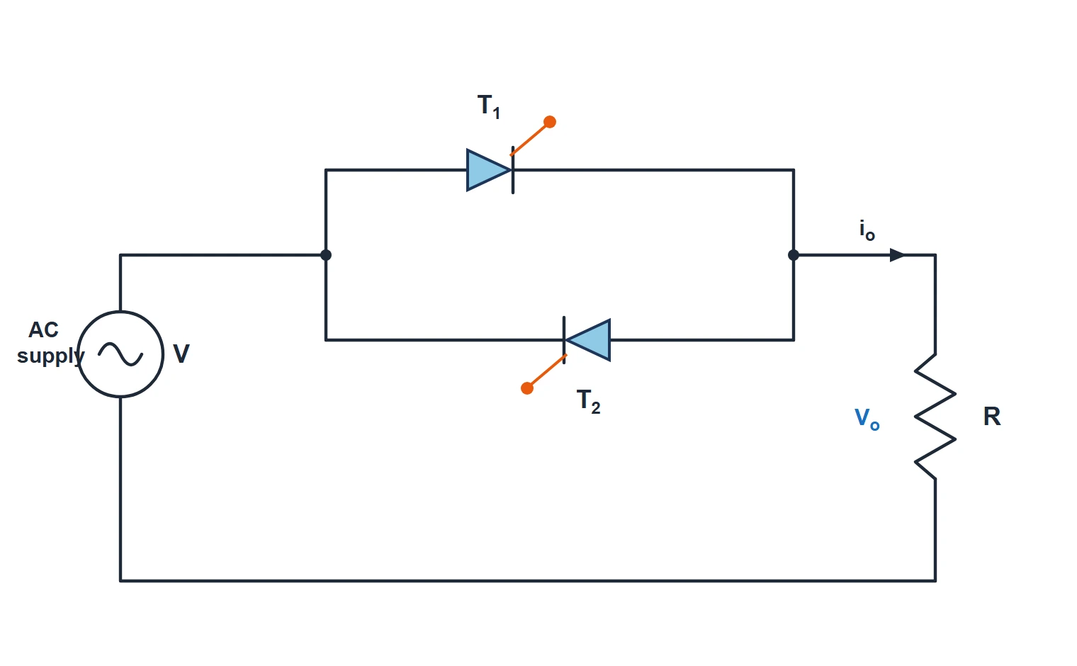
Look closely at how the two thyristors are arranged. They are wired in parallel but pointing in opposite directions — the anode of T1 is joined to the cathode of T2, and the cathode of T1 is joined to the anode of T2. This anti-parallel pair sits directly between the supply and the load.
Because each thyristor can only pass current in one direction (anode to cathode), the pair together can carry current in both directions:
- T1 is oriented to conduct during the positive half-cycle, steering current from the supply into the load.
- T2 is oriented to conduct during the negative half-cycle, carrying the reverse current.
Each thyristor has its own gate terminal (the small stubs marked with a dot in the figure). A trigger pulse applied to a gate is what turns that thyristor on. The two gate-drive circuits must be kept electrically isolated from each other, and their trigger pulses are spaced exactly 180° apart, so that T1 is fired in the positive half and T2 in the negative half.
Modes of Operation
With a resistive load the circuit has two active conduction modes per cycle — one for each thyristor — separated by short "off" intervals set by the firing angle α. The two modes are described below directly from the circuit connections, without needing a separate diagram for each state.
Positive Half-Cycle — Thyristor T1 Conducts
During the positive half-cycle the supply makes the anode of T1 positive with respect to its cathode, so T1 is forward-biased and ready to conduct. It does not turn on immediately, though — it stays off until a trigger pulse arrives at its gate at the firing angle α. From 0 to α, both thyristors are off and no voltage appears across the load.
The moment T1 is fired (at ωt = α), it switches on and connects the supply straight across the load. The full instantaneous supply voltage now appears across R, and current flows from the source, through T1, into the load. Because the load is purely resistive, the current is exactly in step with the voltage. As the supply voltage falls back towards zero at the end of the half-cycle (ωt = π), the current also falls to zero, and T1 turns itself off naturally — this is called natural or line commutation. So T1 conducts from α to π.
Negative Half-Cycle — Thyristor T2 Conducts
In the negative half-cycle the supply polarity reverses, making the anode of T2 positive with respect to its cathode. Now T2 is forward-biased while T1 is reverse-biased and firmly off. Exactly one half-period later than T1 — that is, at ωt = π + α — a trigger pulse is applied to the gate of T2, turning it on.
T2 then connects the (now negative) supply across the load, and current flows through the load in the opposite direction to before. Once again the resistive current follows the voltage and falls to zero at the end of the half-cycle (ωt = 2π), so T2 also commutates naturally. T2 therefore conducts from π + α to 2π. The whole pattern then repeats for every input cycle.
The key takeaway: increasing α delays both firings equally, shortening the conduction window in each half-cycle. Because both halves are treated identically, the output stays symmetrical — equal positive and negative areas — and therefore carries no DC component.
Waveforms & Explanation
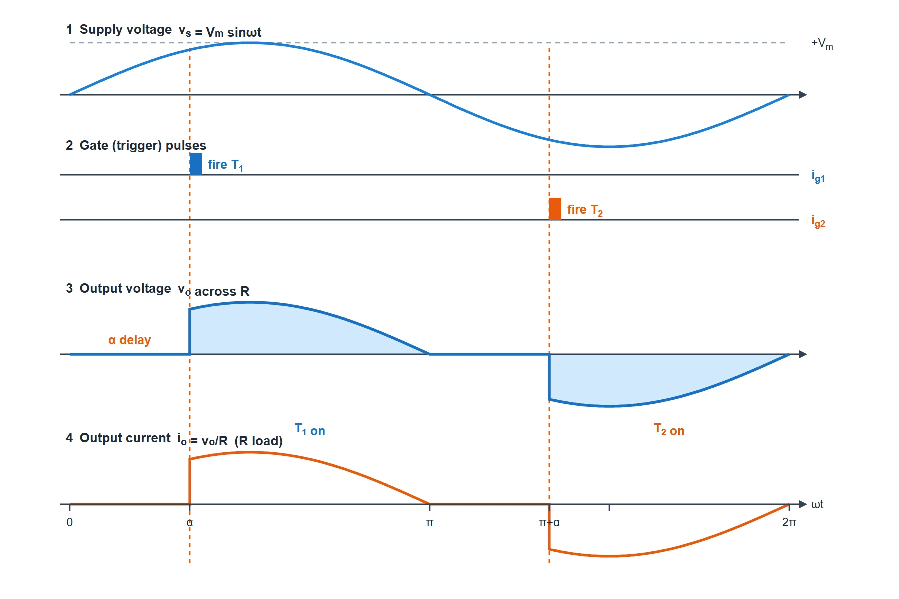
The figure below stacks four synchronized views on the same time axis (ωt) for a firing angle of α = 60°: the supply voltage, the gate trigger pulses, the resulting output voltage across R, and the output current.
Reading the Waveforms
- Supply voltage vs: a clean sine wave, vs = Vm sinωt. This is what would reach the load if the thyristors were fully on (α = 0).
- Gate pulses (ig1, ig2): a narrow pulse fires T1 at ωt = α and a second pulse fires T2 exactly 180° later at ωt = π + α. The delay of each pulse from the start of its half-cycle is the firing angle.
- Output voltage vo: the load is disconnected from 0 to α (so vo = 0), then the supply voltage suddenly appears the instant T1 fires and follows the sine down to zero at π. The same thing happens in the negative half after T2 fires. The output is therefore a "chopped" sine — each half-cycle is missing its first α degrees.
- Sudden jump at firing: notice the vertical step in vo at α and π + α. The voltage jumps instantly from 0 up to Vm sinα because the thyristor connects the load to a supply that is already part-way up its sine wave. This abrupt edge is the source of the switching harmonics that phase control produces.
- Output current io: for a resistive load the current is simply vo/R, so it has exactly the same shape as the output voltage — it starts abruptly at firing and returns to zero at the natural zero-crossing.
- Conduction angle: each thyristor conducts for (π − α) radians. At α = 60° each device conducts for 120° of every half-cycle.
- No DC component: the positive and negative halves are mirror images, so their areas cancel — the average of vo over a full cycle is zero, exactly as an AC output should be.
Output Voltage & Formulas
The most useful quantity is the RMS output voltage, because that is what sets the power delivered to a resistive load. Let Vs be the RMS value of the supply (Vs = Vm/√2) and α the firing angle in radians. Integrating the chopped sine over one half-cycle gives:
The other key relationships for a resistive load follow directly:
| Quantity | Formula |
|---|---|
| Supply RMS voltage | Vs = Vm/√2 |
| RMS output voltage | Vo(rms) = Vs√[(1/π)(π−α+½sin2α)] |
| RMS output current | Io(rms) = Vo(rms) / R |
| Power delivered to load | P = Vo(rms)2 / R |
| Conduction angle (per half-cycle) | γ = π − α |
| Range of firing angle | 0 ≤ α ≤ π (0° to 180°) |
| Average output voltage (full cycle) | Vavg = 0 (symmetrical AC) |
Two useful checks: at α = 0 the bracket becomes (1/π)(π) = 1, so Vo(rms) = Vs — the full supply reaches the load. At α = π the bracket is zero, so Vo(rms) = 0 — the load is fully off. Every value in between lets you set the RMS voltage anywhere from 100% down to 0%.
Control Characteristic
Plotting the RMS output voltage (as a fraction of the supply) against the firing angle gives the control characteristic. It shows at a glance how the firing angle sets the output: near α = 0 the output is almost the full supply, it falls steeply through the middle of the range, and reaches zero at α = 180°.
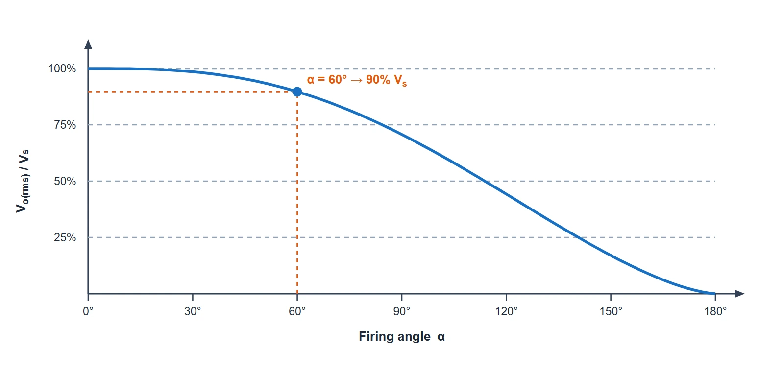
The curve is not a straight line — it is flattest near the ends and steepest around α = 90°, which is worth remembering when designing a dimmer or regulator: a given change in firing angle has the biggest effect on brightness or heat near the middle of the range.
A Note on R-L Loads
The circuit above and all the waveforms use a purely resistive (R) load, which keeps the behaviour simple: the current follows the voltage and stops exactly at the zero-crossing. Many real loads (motors, transformers, solenoids) are inductive (R-L), and there the story changes in two important ways:
- The inductance delays the current, so it does not fall to zero at π. The thyristor keeps conducting past the zero-crossing until the current finally reaches zero at an extinction angle β > π.
- The lower useful range of α is limited: firing angles below the load's phase angle no longer give control, and short gate pulses may fail to keep the thyristor latched, so a train of pulses or a wider gate pulse is used.
The R-L analysis is a separate topic; this page deliberately keeps to the clear R-load case.
Advantages & Disadvantages
Advantages
- Bidirectional, full-wave control of both half-cycles, so no DC component and no transformer saturation.
- Simple and robust — few components, no moving parts, high efficiency.
- Smooth, continuous adjustment of output voltage from 0 to full supply.
- Natural (line) commutation — no separate turn-off circuitry is needed.
Disadvantages
- The chopped output is rich in harmonics, which can disturb other equipment and need filtering.
- Phase control gives a poor input power factor at large firing angles.
- Two thyristors need isolated gate-drive circuits with pulses 180° apart, adding complexity compared with a single TRIAC.
- Only suitable where a reduced voltage at the same frequency is wanted — it cannot raise the voltage or change the frequency.
Applications
- Lighting control — lamp dimmers for incandescent and halogen lamps.
- Heating control — industrial furnaces, ovens and domestic heaters.
- Fan and small-motor speed control — ceiling-fan regulators and universal-motor tools.
- Motor soft-starters — ramping the voltage to induction motors to limit starting current.
- AC voltage stabilisers and transformer tap-changing assistance.