Three-Phase Dual Converter
Two three-phase full converters sit back-to-back across one load, so a big DC motor can run forwards, run backwards, and brake energy back into the mains — all with a smooth 6-pulse output.
- Introduction
- What is a Three-Phase Dual Converter?
- Positive Group & Negative Group
- Circuit Diagram & Construction
- How It Works (α1 + α2 = 180°)
- Modes of Operation
- Output Voltage Waveforms (6-Pulse)
- Current Waveforms (Circulating Current)
- Four-Quadrant Operation
- Three-Phase vs Single-Phase Dual Converter
- Key Parameters & Formulas
- Advantages & Disadvantages
- Applications
- Frequently Asked Questions – FAQs
- Related Topics
Introduction
For anything above a few kilowatts, DC drives are fed from a three-phase full converter rather than a single-phase one. It gives a steadier output, draws power evenly from all three lines, and handles far more current. On its own, though, a single three-phase bridge has the same limit as any thyristor rectifier: current can only flow one way through it. So it can drive a motor in one direction, but it cannot reverse the motor or brake it by pushing energy back to the supply.
A three-phase dual converter removes that limit by using two three-phase bridges together across the same load — one to send current one way, the other to send it back. That single change turns a plain rectifier into a full four-quadrant drive that can motor and brake in both directions. This page keeps the explanation simple: what the circuit is, the one firing rule that ties the two bridges together, the two current modes, the 6-pulse output waveform, and where these converters are used.
What is a Three-Phase Dual Converter?
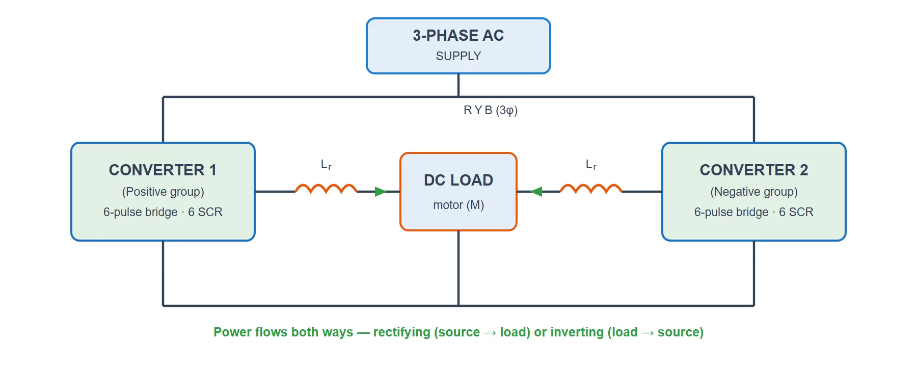
A three-phase dual converter is simply two three-phase full converters connected back-to-back across one load. Each bridge is a six-pulse converter built from six thyristors, so the pair uses twelve thyristors in total. The two bridges face the load from opposite directions: one is set up to pass positive load current, the other to pass negative load current.
At any moment one bridge does the real work as a rectifier (taking power from the three-phase mains and feeding the load), while the other stands ready to run as an inverter (returning energy from the load to the mains). Which bridge is which depends only on their firing angles, and those two angles are tied together by one short rule:
Keeping the two angles supplementary (adding up to 180°) makes both bridges settle on the same average output voltage, so they agree on the DC level the load sees. Turn the control angle and both bridges move together.
Positive Group & Negative Group
The two bridges are named after the direction of load current each one is able to carry:
- Positive group (Converter 1): carries positive load current. When it is active it usually works as a rectifier, with its firing angle below 90°, pushing power from the mains into the load.
- Negative group (Converter 2): carries negative load current. When it takes over it usually works as an inverter, with its firing angle above 90°, sending stored energy from the load back to the mains.
A bridge rectifies when its firing angle is under 90° and inverts when it is over 90°. To reverse the motor or to brake it, the control simply hands the current from one group to the other and swaps their roles.
Circuit Diagram & Construction
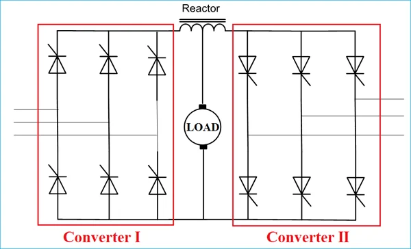
The parts of a three-phase dual converter are:
- Converter 1 — a three-phase full bridge of six thyristors (the positive group).
- Converter 2 — a second three-phase full bridge of six thyristors (the negative group), connected the opposite way round. That makes twelve thyristors in all.
- A common load — usually the armature of a large separately excited DC motor.
- Current-limiting reactors — inductors placed between the two bridges. In the circulating-current mode they soak up the small voltage difference between the bridges and hold the circulating current down to a safe value.
Both bridges take their power from the same three-phase supply and connect to the load from opposite sides. A firing (gate-control) circuit produces both sets of pulses and keeps α1 + α2 = 180° at all times so the two average voltages stay matched.
How It Works (α1 + α2 = 180°)
A three-phase full converter fired at an angle α gives an average DC output of Edc = (3√3 Vm/π) cosα, where Vm is the peak of the phase voltage. (Written with the peak line-to-line voltage VmL it is the tidy form Edc = (3VmL/π) cosα.) Calling the no-delay maximum Emax = 3√3 Vm/π, the two bridges give:
For the two bridges to hold the same voltage across the load, one must be as positive as the other is negative, i.e. Edc1 = −Edc2. Put the formulas in and that becomes cosα1 = −cosα2, which is true only when the angles are supplementary:
So while one bridge rectifies at a small angle, its partner waits at the supplementary angle, poised to invert the moment the drive needs to brake or change direction.
Modes of Operation
The 180° rule matches the two average voltages, but the two bridges never produce the exact same instantaneous waveform — their ripple is slightly out of step. There are two standard ways to run the converter, depending on how you deal with that mismatch.
1. Non-Circulating Current Mode
Here only one bridge is switched on at a time; the gate pulses to the resting bridge are removed completely. Since the two bridges are never live together, no current can loop between them, so no reactor is needed. To change the direction of current, the control blocks the working bridge, waits a short dead time (about 10–20 ms) to be certain its thyristors have turned off, and only then starts the other bridge. The reward is better efficiency and a cleaner input power factor; the cost is that changeover delay, which briefly interrupts the load current and needs careful control.
2. Circulating Current Mode
Here both bridges stay on together, locked at α1 + α2 = 180°. Their averages cancel around the loop, but the leftover ripple does not, so a small circulating current flows between the two bridges. Current-limiting reactors in that loop absorb the ripple voltage and keep the circulating current small. Because both bridges are always ready, current passes from one group to the other with almost no delay, the load current stays smooth and continuous, and the control is simpler. The trade-off is the extra reactors, slightly larger devices and a little lost efficiency.
Output Voltage Waveforms (6-Pulse)
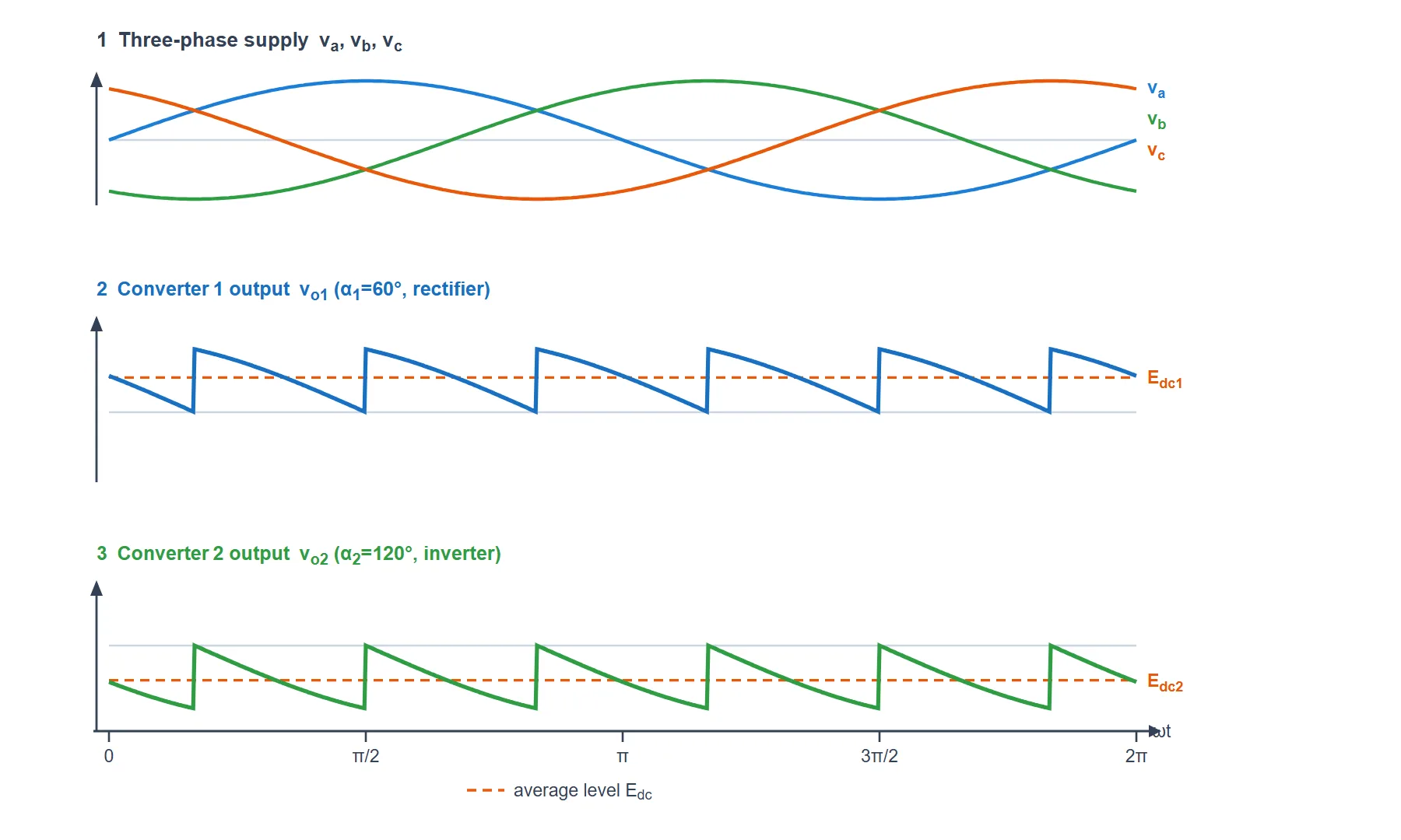
The traces below are worked out straight from the formulas above, for converter 1 fired at α1 = 60° (rectifying) and converter 2 at α2 = 120° (inverting). The top panel shows the three supply-phase voltages; the lower two show each bridge’s DC output with its average level marked. Notice how each output is built from six humps per cycle — that is what “six-pulse” means.
Reading the Waveform
- Three-phase supply: the three phase voltages va, vb, vc are ordinary sines spaced 120° apart.
- Converter 1 output vo1: at α1 = 60° the bridge stitches together six sine-tops per cycle. The trace stays well above zero and its average Edc1 is positive (orange dashed line) — bridge 1 is rectifying.
- Converter 2 output vo2: the same six-pulse shape at α2 = 120°, but now it sits below zero. Its average Edc2 is negative — bridge 2 is inverting.
- Equal magnitudes: because α1 + α2 = 180°, the two averages are the same size (|Edc1| = |Edc2|). That is exactly what lets the two bridges share one load voltage.
- Smoother than single-phase: six humps per cycle means the ripple repeats at 6× the supply frequency (300 Hz on a 50 Hz line), so the DC is far flatter and needs little filtering.
- Circulating current: the two instantaneous traces are not identical, so their difference appears across the reactors and drives the small circulating current in the circulating-current mode.
Current Waveforms (Circulating-Current Mode)
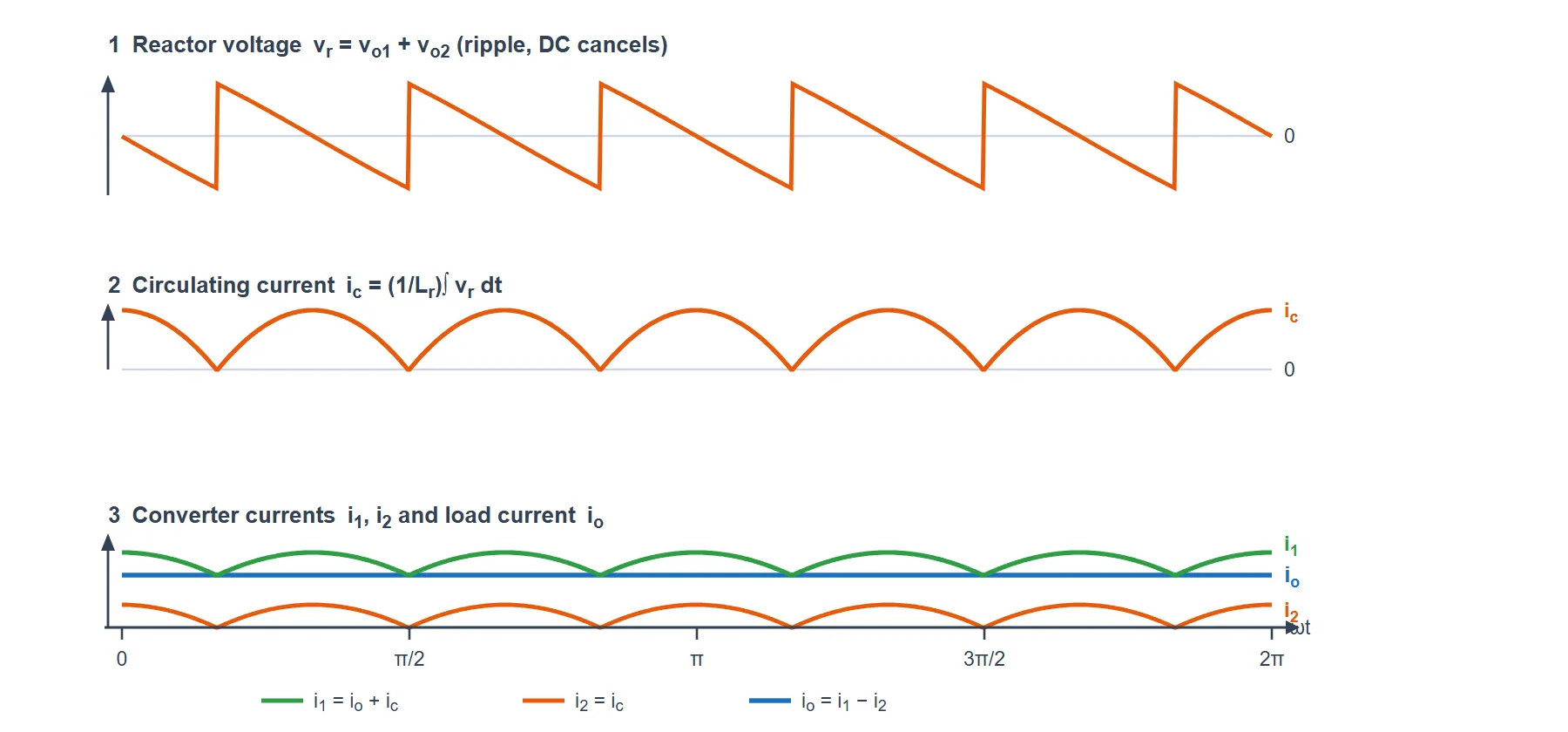
The voltage waveforms above tell only half the story. In the circulating-current mode both bridges stay switched on, so there are three currents worth looking at as well: the ripple voltage across the reactor, the small circulating current it drives, and the load current together with how the two bridges share it. They are all drawn for the same case (α1 = 60°, α2 = 120°). The shapes are exact in time; the amplitudes are illustrative, since the real sizes are set by the reactor Lr and the load.
Reading the Current Waveforms
- Reactor voltage vr: at every instant the two bridge outputs differ a little. Their DC parts cancel (that is what α1 + α2 = 180° guarantees), so what is left across the reactor is a pure 6-pulse ripple at 300 Hz with no average value.
- Circulating current ic: the reactor turns voltage into current by integrating it, so this ripple voltage produces a small, smooth triangular circulating current. It is deliberately kept above zero so both bridges never stop conducting — that continuous conduction is exactly why the reactor is fitted.
- Load current io: with a highly inductive load (a motor armature) the load current is smooth and almost flat. Because it never falls to zero, the drive can hand current from one bridge to the other instantly, with no gap.
- Converter currents i1, i2: one bridge carries the load current plus the circulating current (i1 = io + ic) while the other carries only the circulating current (i2 = ic). Their difference is the load current, io = i1 − i2. Inside each bridge, every thyristor still conducts for 120°.
- In the non-circulating mode there is no reactor and only one bridge conducts, so ic is zero and the resting bridge’s current is zero — the load current simply pauses for the short dead time during a changeover.
Four-Quadrant Operation
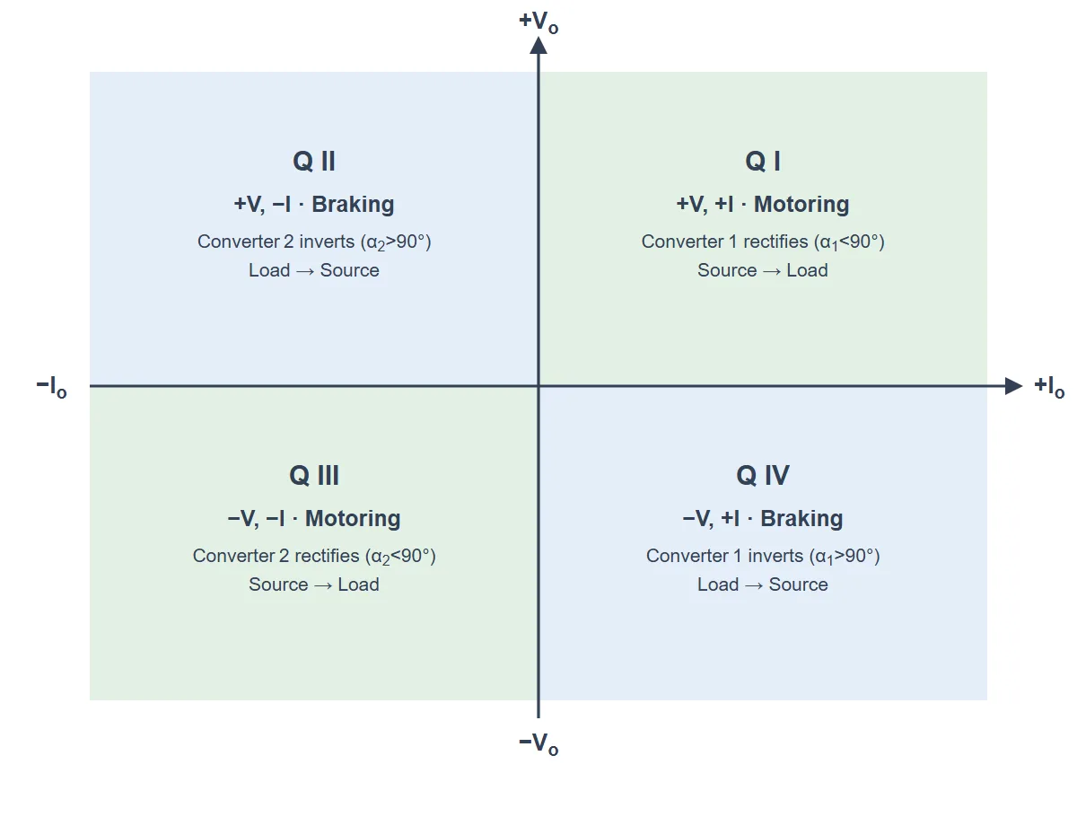
Plot output voltage Vo against output current Io and you get four regions. A dual converter can work in all four, which is why it suits reversible drives. When Vo and Io share the same sign the load takes in power (motoring); when their signs differ, power flows back to the mains (braking / regeneration).
| Quadrant | Voltage / Current | Operation | Active bridge | Power flow |
|---|---|---|---|---|
| I | +V, +I | Forward motoring | Converter 1 — rectifier (α1<90°) | Source → Load |
| II | +V, −I | Regenerative braking | Converter 2 — inverter (α2>90°) | Load → Source |
| III | −V, −I | Reverse motoring | Converter 2 — rectifier (α2<90°) | Source → Load |
| IV | −V, +I | Regenerative braking | Converter 1 — inverter (α1>90°) | Load → Source |
Three-Phase vs Single-Phase Dual Converter
Both do the same four-quadrant job; the three-phase version is the one you reach for on larger drives:
| Feature | Single-Phase Dual Converter | Three-Phase Dual Converter |
|---|---|---|
| Thyristors | 8 (two 4-SCR bridges) | 12 (two 6-SCR bridges) |
| Pulses per cycle | 2-pulse | 6-pulse |
| Average output | Edc = (2Vm/π) cosα | Edc = (3√3 Vm/π) cosα |
| Output ripple frequency | 2f (100 Hz at 50 Hz) | 6f (300 Hz at 50 Hz) |
| Output smoothness | More ripple, needs more filtering | Much smoother DC |
| Typical power range | Small to medium drives | Medium to very large drives |
| Supply loading | Single-phase | Balanced across all three lines |
Key Parameters & Formulas
For a three-phase dual converter with peak phase voltage Vm (peak line-to-line VmL = √3 Vm) and firing angles α1, α2:
| Quantity | Formula & Value |
|---|---|
| Maximum average voltage | Emax = 3√3 Vm/π = 3VmL/π ≈ 1.654 Vm |
| Converter 1 average output | Edc1 = Emax cosα1 |
| Converter 2 average output | Edc2 = Emax cosα2 |
| Firing-angle relationship | α1 + α2 = 180° |
| Voltage-matching condition | Edc1 = −Edc2 (equal magnitude) |
| Rectifier / inverter boundary | α < 90° rectifies, α > 90° inverts |
| Number of thyristors | 12 (6 per bridge, each conducts 120°) |
| Output ripple frequency | fripple = 6f (300 Hz for a 50 Hz supply) |
| Quadrants of operation | Four quadrants (±V, ±I) |
Choose α1 and the load voltage follows from Edc1 = Emaxcosα1; α2 = 180° − α1 then falls out on its own, leaving the idle bridge ready to take the current whenever the drive brakes or reverses.
Advantages & Disadvantages
Advantages
- Full four-quadrant control of large DC motors — forward, reverse, and braking in both directions.
- Smooth 6-pulse output with ripple at 300 Hz, so it needs far less filtering than a single-phase design.
- Regenerative braking — braking energy is returned to the mains instead of wasted as heat.
- Balanced three-phase loading and a good, steady power capability for heavy drives.
Disadvantages
- More devices and cost — twelve thyristors plus their gate-drive and protection circuits.
- Reactors required in the circulating-current mode, adding size, weight and some loss.
- More complex control — precise firing so that α1 + α2 = 180°, and a safe changeover in the non-circulating mode.
- Line harmonics — the phase-controlled input current is non-sinusoidal and can lower the supply power factor at large firing angles.
Applications
- Large reversible DC drives in steel rolling mills, where the mill motor must speed up, slow down and reverse repeatedly.
- Mine hoists, winders and large cranes that need controlled lowering with regenerative braking.
- Paper, cement and textile machines that demand steady, four-quadrant speed and torque control.
- Electric traction and other heavy industrial drives fed from a three-phase supply.
- Test benches and dynamometers that must both drive and load a machine under test.